1
L
8-Node
Enhance Micro TDC 3000
Specification and
Technical Data
MT03-420
Release 400
3/95
L
L
L
L
nt
rga
dete
coffee
chocolate
MT03-420
Page 2
8-Node
Enhanced Micro TDC 3000
Table of Contents
Page
Introduction
Architecture
Functional Overview
System Configuration
System Communication
Local Control Network
Universal Control Network
Network Interface Module
Process-Connected Data
Acquisition and Control
Advanced Process Manager
Information Processing and
Advanced Control
Universal Station
Application Module
History Module
System Peripherals
Optional TPLCN Nodes
References
Specifications
2
2
4
4
4
4
5
5
5
5
10
10
11
13
14
14
15
16
Specification and
Technical Data
Introduction
The Enhanced Micro TDC 3000
is a very powerful, standalone
small system, cost-optimized for
continuous, batch and sequential
logic applications. It is ideal for
customers who need the
functionality of Honeywell's
TDC 3000X system, but also
require a smaller system size and
footprint at a significantly lower
cost.
The Enhanced Micro TDC 3000
system provides all of the power
and capability of a standard
Honeywell TDC 3000X
LCN/UCN-based system, in a
smaller, more cost-efficient
package having a prebuilt
network, area and point database.
Almost all the application solution
packages that run on the standard
TDC 3000X system can be run on
the Enhanced Micro TDC 3000
system.
While the Enhanced Micro TDC
3000 is an excellent small system,
it should be noted that the
standard TDC 3000X system is
the preferred choice for those
critical process applications that
require a very high degree of
system reliability, robustness or
redundancy. Enhanced Micro
TDC 3000 is not intended for
such applications, and should not
be used in place of a standard
TDC 3000X system in such
situations.
Architecture
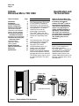
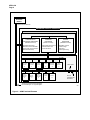
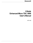
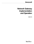
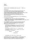
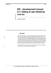
Figure 1 is an illustration of a
typical Enhanced Micro
TDC 3000 system. It consists of
an Advanced Process Manager
(APM) cabinet plus two other
cabinets (called "towers") that
contain additional electronics, two
Bernoulli (cartridge) drives, and a
hard disk drive.
Monitor (US)
Printer
Micro Towers
(Table Not Included)
APM
Figure 1 — Enhanced Micro TDC 3000 System
52565
MT03-420
Page 3
The electronics in the towers are
patterned after (but not identical
to) the standard TDC 3000X LCN
nodes such as the Application
Module (AM), History Module
(HM), Network Interface Module
(NIM), and the Universal Station
(US).
Each tower has a multinode
module (cardfile) capable of
housing up to four nodes using
K2LCN1 processors, thus allowing
a maximum of eight nodes per
Enhanced Micro TDC 3000
system. Of these eight nodes, up
to four may be Universal Station
(US) nodes. The two towers are
connected by a Twisted Pair Local
Control Network (TPLCN) cable.
The Network Interface Module
(NIM) allows the tower (LCN)
nodes to communicate with the
process over the Honeywell
Universal Control Network (UCN).
The process itself is monitored
and controlled by the APM
(Advanced Process Manager),
which resides on the UCN, and is
connected to the LCN nodes via
the NIM. The APM is an integral
part of the Enhanced Micro
TDC 3000 system.
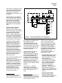
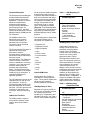
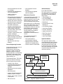
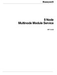
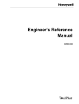
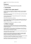
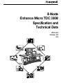
Figure 2 shows the architecture of
a typical Enhanced Micro
TDC 3000 system, depicting the
nodes used to construct this
sample system. As may be seen
in Figure 2, a second (optional)
NIM may be installed in Tower #2
to also connect to the APM and
provide redundancy. (The
standard NIM supplied with all
Enhanced Micro TDC 3000
systems is in Tower #1.)
1K2LCN is Honeywell's proprietary
processor board that utilizes a
Motorola 68020 microprocessor chip.
(Example)
Tower #2
Optional
Universal
Station
Optional
Programmable
Logic
Controller
Gateway
DEC
VAX
Tower #1
History
Module
Application
Module
Universal
Station
Computer
Gateway
LCN
Optional
Redundant
Network
Interface
Module
620
LCS
(Example)
Network
Interface
Module
Advanced
Process
Manager
UNIVERSAL
CONTROL NETWORK
Other system components include
color monitor(s), keyboard(s), an
optional touchscreen or trackball,
and a printer, all of which are
supported by the electronics in the
two towers.
Advanced
Process
Manager
Process
Manager
Logic
Manager
6722
Figure 2 — Typical Enhanced Micro TDC 3000 System
Also supplied as standard nodes
with all Enhanced Micro
TDC 3000 systems are an AM
(Application Module) and a US
(Universal Station)2, both of which
are also housed in Tower #1, and
an HM (History Module) which is
installed in Tower #2.
Other optional nodes such as
additional USs, Computer
Gateway (CG), Network Gateway
(NG), and PLC Gateway (PLCG)
are also available and may be
installed in the towers to expand
the system (up to a maximum of
eight nodes). A short functional
description of each of these
system expansion options is given
on page 14 (see "Optional TPLCN
Nodes").
Each tower (i.e., multinode
cardfile) has an independent
power supply, which is shared by
all the nodes installed in that
tower.
2Some ("Version B") Enhanced Micro
TDC 3000 systems have a second US
supplied as standard with the system,
which is installed in Tower #2.
Thus, up to four nodes could
share a single power supply
(unlike the standard TDC 3000X
system, where each node has an
independent power supply).
Following is a brief description of
the standard LCN/UCN nodes
supplied with an Enhanced Micro
TDC 3000 system (see
"Specifications" for additional
technical information):
• Universal Station (US): Provides
a window to the process, and
allows information from processconnected devices,
instrumentation subsystems,
and computers to be seen and
used. The US(s) supplied as
standard with all Enhanced
Micro TDC 3000 systems
support the "Universal"
personality. Optional USs that
support either "Universal" or
"Operator" personalities are also
available (see “Optional TPLCN
Nodes”).
• Application Module (AM):
Performs calculations and
advanced control strategies that
are not possible or practical
MT03-420
Page 4
using only process-connected
devices.
There is one AM per Enhanced
Micro TDC 3000 system. The
AM is offered in two standard
memory sizes — 2 Mw or 8 Mw.
• History Module (HM): Provides
mass storage of software,
system data, and customer data
on a hard disk drive. There is
one HM per Enhanced Micro
TDC 3000 system.
• Network Interface
Module (NIM): Connects the
Enhanced Micro TDC 3000
System to a process control
device through the Universal
Control Network. A second NIM
(optional), may be added to the
system for redundancy.
• Advanced Process Manager
(APM): Provides highly flexible
I/O functions for both data
acquisition and control.
One APM is supplied as standard
with each Enhanced Micro
TDC 3000 system. (For additional
information on the APM see
“Process-Connected Data
Acquisition and Control.”)
Functional Overview
The Enhanced Micro TDC 3000
system is designed on a global
database concept. Data is kept in
only one location; therefore,
information displayed on two
different USs is identical. This is
true for other nodes as well.
The Enhanced Micro TDC 3000
system integrates information and
control and makes available the
data necessary for making
operating and management
decisions, through a single
window. Enhanced Micro
TDC 3000 systems satisfy a wide
range of information and control
requirements including the
following items:
•
•
•
•
•
•
•
•
Data acquisition
A single window to the process
Incremental levels of control
Advanced control capability
History collection
Reporting
Graphics
Communication with a userselected host computer
• Communication with
programmable controller
networks
More details on the functions
provided by the Enhanced Micro
TDC 3000 system can be found
under the section headings
“System Communication,”
“Information Processing and
Advanced Control,” and “ProcessConnected Data Acquisition and
Control.”
System Configuration
Functional Description
The TPLCN is similar to the LCN
(Local Control Network) used in
other TDC 3000 equipment, but
a noncoaxial RS-485 (twisted pair)
network has been chosen
because of its simplicity and the
short distances between nodes.
Distributed processing with
centralized operations is a reality in
Enhanced Micro TDC 3000
systems because the TPLCN
provides rapid, secure
communication between all
modules. Information is
transferred serially at 5 million bits
per second. All modules are
assured access to the network,
even during a peak load.
Communication delays do not
become excessive because a
deterministic token-passing
algorithm is employed to control
access to the network.
Reliability
The Enhanced Micro TDC 3000
system consists of a limited set of
equipment and functions.
Prebuilt configuration files are
supplied to configure the network
including the US, AM, HM, and
NIM, along with one AM point, and
one Area Database. Two USs and
two NIMs are defined in the
standard configuration file, but if
only one of these pairs is actually
present, the other will be shown
as OFF on the status display.
Prebuilt files and 15 APM points
are supplied for the APM.
Dual cables, CRC verification on
every received frame, and
message-length checks by
software ensure an extremely
reliable network. Undetected
errors are virtually nonexistent in
an Enhanced Micro TDC 3000
system.
This document describes a
standard, prebuilt system. If any
options are implemented or any
nonstandard configuration
functions performed, file changes
may be required.
The TPLCN Interfaces in all
modules have transmission and
reception circuits for both twistedpair cables. Should a cable, a
transmitter circuit, or a receiver
circuit fail, there is a backup to take
over for it.
System Communication
All modules residing on the
TPLCN transmit all frames on both
cables and normally "listen" on the
active cable. If a TPLCN Interface
does not hear anything on the
active cable within the maximum
interframe gap after receiving a
Local Control Network
The Twisted Pair Local Control
Network (TPLCN) is the
communication link between the
nodes in Towers #1 and #2.
A 16-bit polynomial checksum in
each information frame (sized from
100 to 2000 bytes) is used to
check data transmission. If an
error is detected, the frame will be
retransmitted.
MT03-420
Page 5
token pass frame, it switches its
receiver to the backup cable.
Universal Control Network
The Universal Control Network
(UCN), using the NIM, provides
the communication link between
UCN-resident modules such as
the Advanced Process Manager
and the Logic Manager (optional),
and the TPLCN-resident modules
such as a US, HM, AM, and
Computer Gateway (optional).
Functional Description
The UCN is a high-speed, highsecurity, process control network.
Based on IEEE 802.4 (ISO
8802/4) and extended message
services, the UCN operates at a 5
megabit/second rate using
efficient message structures to
support the high-speed
communications requirements of
process devices.
UCN communications are
consistent with the growth and
direction of evolving international
standards for Open Architecture
and industrial specifications such
as real-time MAP. The use of
these standards facilitates future
interconnection of multivendor
devices.
Information from UCN devices
(process status, configuration,
etc.) is transferred through the
NIM to the TPLCN. This data is
used for the Micro TDC 3000
operator, control, history, and
management functions.
Commands and configuration
information for data points are
transferred from the TPLCN
through the NIM to the UCN.
The UCN supports peer-to-peer
communications. This means that
UCN devices can write data to and
read data from other UCN devices
for additional control strategy,
flexibility, and coordination.
Reliability
The use of dual cables, 32-bit
CRC frame-check sequence
verification on every received
frame, and message-length
checks by the software ensure an
extremely reliable network.
Detected errors can be corrected
by a repeat transmission from the
sending device.
The UCN interfaces in all modules
have transmission and reception
circuits for both coaxial cables.
The transmitter and receiver
circuits are transformer-coupled to
provide electrical isolation
between the modules on the
network. They are designed so
that a circuit failure cannot affect
the operation of the cables or
other devices connected to the
UCN. Additional protection
against individual device faults is
provided by cable taps that isolate
the drops and devices from the
trunk cable.
A second level of security is built
into each network device in the
form of diagnostic software that
monitors and reports numerous
device and parameter error
conditions. These checks assure
a high-performance, real-time
network with message security.
To verify its ability to communicate
over the UCN, each device
continually performs a set of
diagnostic tests to determine the
status of the two cables. This
includes periodic switching of
cables and monitoring each cable
for noise interference or silence,
which would indicate that a failure
has occurred. Each device also
monitors itself for excessive,
continuous transmission, and
shuts down its own modem if that
condition is detected.
Network Interface Module
The NIM provides the
communication link between the
TPLCN (Twisted Pair Local Control
Network) and the UCN.
Functional Description
The NIM makes the transition from
the transmission technique and
protocol of the TPLCN to the
transmission technique and
protocol of the UCN. The NIM
provides TPLCN modules access
to data from UCN-resident
devices, such as Advanced
Process Manager, Process
Manager, and Logic Manager.
Alarms and messages are
forwarded from these UCN
devices to TPLCN-resident
devices such as USs, HMs, AMs,
and Computer Gateways
(optional).
Process-Connected Data
Acquisition and Control
The Enhanced Micro TDC 3000
system incorporates Honeywell’s
most powerful advance in data
acquisition and control devices,
the Advanced Process Manager
(APM).
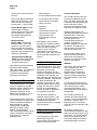
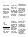
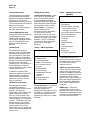
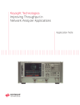
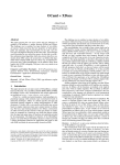
Advanced Process Manager
The field I/O devices are
connected to the APM through
Field Termination Devices. See
Figure 3 for details. The APM is a
fully integrated member of the
TDC 3000X family capable of:
• Performing data acquisition and
control functions, including
regulatory, logic, and sequential
control functions, as well as
peer-to-peer communications
with other UCN devices.
• Providing bidirectional
communications to Modbus™
and Allen-Bradley™ compatible
subsystems through a serial
interface.
• Fully communicating with
operators or engineers at
Universal Stations. Procedures
and displays are identical or
similar to those for other
TDC 3000X controllers. Plant
personnel may already be
familiar with them.
• Supporting higher level control
strategies available on the Local
Control Network through the
Application Module and host
computers.
MT03-420
Page 6
NETWORK
INTERFACE
MODULE
Universal Control Network
ADVANCED PROCESS MANAGER
Optional Redundant APMM
ADVANCED PROCESS MANAGER MODULE (APMM)
ADVANCED
COMMUNICATION
PROCESSOR AND MODEM
(M68000 Processor)
UCN Network Support
Network Access to PM Data
Peer-to-Peer Communication
Network Redundancy
ADVANCED I/O LINK
INTERFACE
PROCESSOR
(80C31 Processor)
High-Speed I/O Access for
Communications and
Control Functions
ADVANCED
CONTROL
PROCESSOR
(M68000 Processor)
Regulatory Control
Interlock Logic
Sequence
User Programming
I/O SUBSYSTEM (80C31 Processors)
I/O LINK
High Level
Analog Input
Processor
16
Low Level
Analog Input
Processor
8
Analog
Output
Processor
8
Digital Input
Processor
32
Digital Input
Sequence
of Events
32
Smart
Transmitter
Interface
16
Serial
Device
Interface
16
LL Mux
Analog Input
Processor
32
Pulse Input
Processor
Serial
Interface
8
32
Digital
Output
Processor
16
Fiber Optics
I/O Link
To Remote I/O
Processors
To Other Advanced Process Managers,
Process Managers, or Logic Managers.
6202
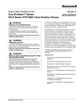
Figure 3 — APM Functional Elements
MT03-420
Page 7
Functional Description
The Advanced Process Manager
provides flexible and powerful
process scanning and control
capabilities. To do this, it uses an
advanced multiprocessor
architecture with separate
microprocessors dedicated to
perform specific tasks. As
depicted in Figure 3, the APM
consists of the Advanced Process
Manager Module (APMM) and the
I/O Subsystem.
The APMM consists of an
Advanced Communication
Processor and modem, an
Advanced I/O Link Interface
Processor, and an Advanced
Control Processor.
The Communication Processor is
optimized to provide highperformance network
communications, handling such
functions as network data access
and peer-to-peer
communications. The Advanced
Control Processor is the APM
resource dedicated to executing
regulatory, logic, and sequence
functions, and includes an
excellent user programming
facility. The Advanced I/O Link
Interface Processor is the APMM
interface to its I/O subsystem. A
redundant APMM can be
optionally provided.
The I/O Subsystem consists of the
redundant I/O Link and up to 40
I/O Processors. These I/O
Processors handle all field I/O for
both data acquisition and control
functions. The IOPs provide such
functions as engineering unit
conversion, alarm limit checking,
etc.
APM Control Functions
The APM provides a variety of
control tools to address a wide
range of process automation
needs.
All I/O values are initially converted
to engineering units by the I/O
Processors and made available for
both communications and further
control processing by the APMM.
Conceptually, the APMM can be
thought of as partitioned into
configurable "slots" of various
types. A tagged slot is called a
data point. In an Enhanced Micro
TDC 3000 system, data points are
supported by predefined group
and detail displays and by custom
graphics.
The following types of data points
(descriptions follow) can be
configured into APMM slots:
•
•
•
•
•
•
•
•
•
•
•
•
Regulatory PV
Regulatory Control
Digital Composite
Logic
Device Control
Process Module
Array
Flag
Numeric
Timer
String
Time
Prebuilt APM Points
Configuration files provide 15
APM points of several different
types. These prebuilt APM points
can be used as models for
building additional APM points.
APM Regulatory PV Point
Regulatory PV points provide an
easy-to-use configurable method
for implementing Process
Variable (PV) compensation and
calculation functions. See Table 1
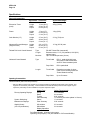
for a list of the available algorithms.
Table 1 — APM Regulatory PV
Points
Available Algorithms
Data Acquisition
Flow Compensation
Middle-of-3 Selector
High/Low/Average Selector
Summer
Totalizer
Variable Dead Time
with Lead/Lag
General Linearization
Calculator
APM Regulatory Control Point
Configurable regulatory (or
analog) control functions are
performed using Regulatory
Control points. Regulatory
Control points are configured to
execute one of the control
algorithms listed in Table 2.
Each algorithm includes a wide
range of configurable options to
allow implementation of complex
control strategies by a simple
menu-selection process. In
addition, some functions such as
initialization and windup protection
are inherently provided. The
capability to ramp setpoint (by
operator entry of a target value
and ramp time) is configurable. A
number of standard and custom
graphic displays are available to
support these control strategies.
Table 2 — APM Regulatory
Control Data Points
Available Algorithms
PID
PID with Feedforward
PID with External Reset
Feedback
PID with Position Proportional
Position Proportional
Ratio Control
Ramp Soak
Auto/Manual Station
Incremental Summer
Switch
Override Selector
MT03-420
Page 8
APM Digital Composite Point
APM Device Control Point
Digital Composite points are multiinput/multi-output points that
provide an interface to discrete
devices, such as motors, pumps,
solenoid valves, etc. This point
provides built-in structures for
handling interlocks. In addition,
provision is made for handling
manual/off/auto switches
commonly used for local operation
of motorized devices. It supports
operator display of interlock
conditions in group, detail, and
graphic displays. Displays also
contain information needed to
trace interlock cause. Runtime
maintenance statistics for the
discrete device are also
supported.
The APM Device Control point
provides maximum flexibility for
controlling descrete devices. It
combines the digital composite
display and logic control function
under a single tagname. This
provides an enhanced interface
for pumps, motors, and motor
operated valves.
APM Logic Point
APM Logic points provide a
configurable mix of logic block
algorithms that together with
digital composite points provide
the basis for integrated interlock
logic functions. See Table 3 for a
list of the logic block algorithms.
Table 3 — APM Logic Block
Available Algorithms
Logic
Compare Real
Delay
Pulse
Watchdog Timer
Flip-Flop
Check for Bad
Switch
Change Detect
Conceptually, a Logic point can be
thought of as providing the logic
processing equivalent to one or
two pages of relay ladder logic. A
Logic point consists of logic
blocks, flags, numerics, input
connections, and output
connections. Different mixes of
inputs, outputs, and logic blocks
can be optionally selected.
The Device Control point’s single
tagname enhances the operator
interface for motor control points.
Operations are improved because
the operator can see the cause of
the interlock. An analog feedback
signal such as motor control
current is displayed.
Implementation effort is also
reduced through the use of a
simple configuration and standard
graphics for troubleshooting.
Process Module Point – User
Programs
Today's control strategies
frequently need the flexibility of
user programs that can be used
for continuous, batch, or hybrid
applications.
A Process Module point is a
resource for executing user
programs written in Honeywell's
Control Language (CL/APM, an
enhanced version of CL, the
Control Language used by
Honeywell in the AM). CL/APM is
an outstanding sequential control
and computational tool. CL/APM
programs are self-documenting—
an important feature when future
modification of control strategies is
anticipated. Using the US,
programs can be easily modified
and reloaded without affecting
execution of regulatory control,
logic blocks, or other user
programs.
All process module programs can
communicate through the
common system database to
access analog inputs and outputs,
digital inputs and outputs, array
points, logic block states, alarm
states, failure states, numeric
variables, and flags.
CL/APM programs can also
manipulate ASCII values as well as
time data. In addition, each
process module program supports
communication with the operator
and can send or receive data from
other controllers on the UCN.
Process Module points provide a
Phase/Step/Statement structure
that is well-suited for implementing
batch process control functions.
Additionally, a multilevel abnormal
event-handling capability allows
the user to define conditions to
automatically trigger predefined
Hold, Shutdown, or Emergency
Shutdown sequences.
APM Array Point
The Array point provides a flexible,
easy-to-access point structure for
user-defined data. It is especially
useful for advanced control or
batch sequence programs. For
example, an Array point can be
used to store calculation variables
or batch recipe data.
The Array point can also be used
for Serial Interface (SI)
communications to third party
subsystems, such as
programmable logic controllers.
Communication to a Serial
Interface Array point is fully
bidirectional. Data from any Serial
Interface Array point can be
accessed by other APM control
and CL functions such as Device
Control points. This allows
subsystem data to be used for
APM data acquistion and control
strategies, as well as displayed at
the Universal Station.
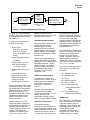
APM I/O Functions
The I/O Processors (IOPs), along
with Field Termination Assemblies
(FTAs), perform input and output
scanning and processing on all
field I/O (Figure 3). I/O link
redundancy provides added
security. Redundancy is also
available for some IOPs. I/O
processing is separate from
control processing, so that I/O
scan rates are entirely
independent of I/O quantity,
controller loading, processing,
MT03-420
Page 9
SP
4-20 MA
FT101
A/D Conversion
EU Conversion
I/O Processor
AI Point
FC101
PV
Control
Algorithm
Alarming
OP
APMM
Regulatory Control
Point
CV101
D/A Conversion
Output Hold Security
Output Characterization
4-20 MA
I/O Processor
AO Point
2062
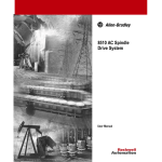
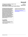
Figure 4 — Typical APM Regulatory Control Loop
and alarming. This partitioning of
functions allows more efficient use
of APM capability and provides for
I/O expansion.
approach simplifies system
hardware selection and minimizes
spare parts requirements.
APM Alarm System Functions
A variety of I/O Processors are
available for the APM:
• Analog Input –
High Level (16 points)
Low Level (8 points)
Low Level Multiplexer (32
Points)
• Smart Transmitter Interface
(16 points)
• Analog Output ( 8 points)
• Serial Device Interface
(16 points, 2 ports)
• Serial Interface (32 arrays, 2
ports)
• Pulse Input (8 points)
• Digital Input (32 points)
• Digital Input Sequence of
Events (32 points)
• Digital Output (16 points)
Any mix of the above IOPs can be
selected for an APM. This can be
any combination of single and/or
redundant (HLAI, STI, and AO)
pairs, up to a total of 40. In a
redundant configuration, control
automatically transfers to the
backup I/O processor during
board replacement.
While more than one FTA is
required to handle varying field
wiring signal levels, the same I/O
Processor can be used for a
number of different sensors. For
example, one Digital Input
Processor can handle 24 Vdc,
120 Vac, or 240 Vac. This
As process alarms occur, they are
visually annunciated at the
Universal Station through
keyboard LEDs and numerous
types of displays such as custom
graphic displays, group displays,
alarm annunciator displays, alarm
summaries etc.
There are four different process
variable alarms and three different
digital alarms. All PV alarms have a
selectable deadband. Contact
cutout is another configurable
feature provided by the APM to
automatically suppress alarm
reporting if certain external
conditions occur.
APM Control Implementation
A simple control loop can be
implemented in an APM, using an
analog input point, a regulatory
control point, and an analog
output point, as shown in
Figure 4.
Although three data points are
used, the primary operator
interface is a single tag (FC101) for
viewing, alarming, and
manipulation through a Group,
Detail, or Custom Graphic Display.
APM Control Performance
The parallel processing
architecture of the APM allows its
control processing capability to be
totally independent of other APM
functions such as the number of
I/O points built, data requests for
APM data from the Network
Interface Module and other UCN
devices, and alarming functions.
Only two factors need to be
considered when configuring the
control processing—the type of
control points (slots) desired and
their frequency of execution or
scheduling interval.
Processing power is measured in
terms of "Processing Units” (PUs).
Each control processor has an
assured rate of 160 PUs per
second. Regulatory, logic and
digital composite, and device
control points can be configured
at different execution frequencies
(1/4, 1/2, or 1 second).
Any mixture of point types can be
used, subject to the following
maximums:
•
•
•
•
•
•
•
160
80
80
512
160
160
Regulatory Control
Regulatory PV
Logic
Digital Composite
Device Control
Process Module (@
1 PU per APM program)
—OR—
80 Process Module (@
2 PUs per APM program)
APM Security
The Advanced Process Manager
has a number of security features
to provide maximum process
availability. A high reliability, faulttolerant approach to the circuitry
and the overall system
architecture has been used
throughout the APM's design.
CMOS technology, including
MT03-420
Page 10
highly heat-tolerant components,
is used to provide a high-density
design with high reliability.
Individual circuitry is used for
critical functions, such as D/A
converters on the output circuitry.
Parallel power paths are employed
so that control outputs can be
maintained even if a power
regulator fails.
Since redundancy options are
designed into the product,
automatic switchover from primary
to redundant electronics is fully
supported. No special user
programming is required.
Ongoing diagnostics are provided
to assure both primary and
redundant electronics are
functional. This one-on-one
approach enhances coverage to
maximize availability. It also
simplifies system cabling and
configuration.
Repairs to the APM can be made
easily by replacing boards while
power is on. Analog and Digital
Standby Manual Units are available
to maintain process outputs
during board replacement.
Overall, the APM provides superb
control capabilities with excellent
process control availability and
security.
Information Processing and
Advanced Control
In the Enhanced Micro TDC 3000
system, information processing
and advanced control functions
are distributed into discrete
modules which provide:
• A single window for access to
the system by all types of
users.
• The information-processing
and storage facilities to support
that access.
• A comprehensive set of
standard control algorithms
together with the ability to
create custom algorithms and
processing routines.
Process
Operator
Displays
Process
Engineer
Displays
Continuous
Process
Operating
Displays
Trend and
Report
Displays
Maintenance
Technician
Displays
Configuration
Displays
Maintenance
Recommendation
Displays
Data-Point
Building
Displays
Display
Memory
Displays
Sequence
Displays
Graphic
Building
Displays
System
Maintenance
Journal Display
Alarm
Displays
CL
Programming
Displays
Maintenance
Aid
Displays
Help
Displays
Log and
Report
Formatting
Displays
TDC 3000
System
Displays
File
Editing
Displays
System
Function
Displays
Utility
Program
Displays
Graphic
Displays
System
Function
Displays
1572
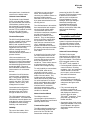
Figure 5 — Displays for Each Type of User
Universal Station
The Universal Station (US)
communicates with the other
modules on the TPLCN, and with
process-connected devices on
the UCN using the NIM.
Display Summary
The process operator, process
engineer, and maintenance
technician communicate with the
process and the system using a
variety of CRT displays. They view
the displays and then either make
keyboard entries or select a target
on the display. Entries can be
made on the operator’s or
engineer’s keyboard, depending
upon the function. Figure 5
shows the three basic US display
types.
Process Operating Functions
The operator can access all the
data needed for normal plant
operation from the US using the
operator’s personality. This data is
presented in displays ranging from
a broad overview to the most
detailed information at the data
point level.
The Enhanced Micro TDC 3000
system provides the following
process operating functions:
• Load other system modules
and process-connected
MT03-420
Page 11
•
•
•
•
•
•
•
•
•
•
devices with data from the HM
or a cartridge.
Reassign USs, area database,
units, and peripherals.
Initiate on-demand
checkpointing.
Review data point assignments
of system modules, processconnected devices, and units.
Monitor and control continuous
and discontinuous processes.
Monitor the status of TPLCN
and UCN modules and
process-connected devices.
Change process parameters,
control modes, sequenceexecution states, and modes.
Annunciate process,
sequence, system alarms, and
operator messages.
Display and print process
trends, averages, and histories.
Display and print reports, logs,
and journals.
Edit Overview and Group
displays.
Process Engineering Functions
In the engineering mode, the US
provides a user-friendly
environment for the process
engineer to build or modify the
database needed to meet his
process objectives. A Help facility
is available to assist with system
data entry for point, display, and
report building, etc.
Maintenance Functions
In the engineering personality, the
maintenance technician can
diagnose problems in the TPLCNbased modules, the UCN, and
UCN-connected process devices.
When faults occur in an Enhanced
Micro TDC 3000 system, they are
usually isolated by built-in tests
and diagnostics that are executed
during startup, restart, and onprocess operation. The fault is
usually isolated to an optimum
replaceable unit, and a
maintenance recommendation is
issued.
The maintenance functions
provided are as follows:
• Call up maintenance
recommendation displays.
• Display and print information
required for troubleshooting.
• Call error detail of a failed node.
BUILT-IN
ALGORITHMS
The Enhanced Micro TDC 3000
system provides the following
process engineering functions:
• Configure the network
• Load operating programs and
databases from the HM or a
cartridge.
• Build the process and system
databases.
• Build data points.
• Custom build and load graphic
displays, reports, and logs.
• Prepare, edit, compile, and link
CL programs.
• Edit source files
Standard Displays
• Call up System Function
displays.
• Load Honeywell-supplied
software updates.
FAST
PROCESSOR
For an Enhanced Micro
TDC 3000 system, the standard
Area Database configuration file
provides the following displays
and journals:
• Group Displays (2)
• Unit Trend Display
• System Status Display
• Reports (2)
• Process Module Group
Displays (3)
• Unit Summary Display
• Annunciator Display
• Process Journals (3)
• System Journals (3)
• Real-Time Journal
• Overview Display
• Area Trend Display
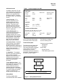
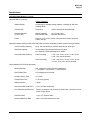
Application Module
The Application Module (AM)
communicates with other modules
on the TPLCN and with processconnected devices on the UCN.
It performs high-level calculations
and control strategies not possible
or practical using only processconnected devices.
CONTROL
LANGUAGE
EXECUTION
SLOW
PROCESSOR
PROCESS DATABASE
LOCAL CONTROL NETWORK
Figure 6 — Application Module Functions
1172
MT03-420
Page 12
Functional Description
AM Regulatory Control
Control strategies in the AM can
be implemented with standard
algorithms and standard data point
processing, or with custom
algorithms and custom processing
routines implemented through the
AM Control Language.
General Input Processing – At the
user's option, a regulatory data
point can fetch values from the
process database and update
designated parameters within the
data point before proceeding with
the remainder of its processing.
See Figure 6 for a description of
the major AM functions.
Configuration files are provided for
one AM regulatory point.
Additional AM regulatory points
can be built by copying this master
point and changing only those
parameter values which are
different.
PV Processing – A regulatory
data point that uses PV
processing fetches designated
PV inputs from a processconnected module on the UCN
before executing the specified PV
algorithm (see Table 4), or custom
algorithm. The PV is calculated,
limit checked, and a value status
(good, bad, or uncertain) is
assigned.
AM Data Points
Table 4 — AM PV Algorithms
Prebuilt AM Regulatory Point
The AM contains a process
database made up of data points
that the process engineer loads
during configuration. Each data
point is a collection of fixed and
dynamic parameters that performs
a specific function and is identified
by a point name. Data point
processing can use predefined or
custom algorithms to calculate
required information and/or initiate
specific control action.
In addition to regulatory data
points that represent continuous
process variables, the AM also
offers several utility data point
types such as timers, counters,
flags, and numerics.
Algorithm Name
Null
Data Acquisition
Flow Compensation
Middle-of-Three Selector
Hi/Lo Average Selector
Summer
Multiplier/Divider
Sum of Products
Variable Dead Time with
Lead-Lag
Totalizer
General Linearization
CL PV Algorithm
AM Data Point Scheduling
Each data point in an AM is
processed according to a
schedule defined by the process
engineer during system
configuration. The engineer may
assign a data point to either a
"fast" or a "slow" processor and
may choose from a variety of time
intervals ranging from 1 second to
24 hours. The fast processor has
a higher priority. The engineer
can also schedule data points to
be processed before or after
another data point, on demand, or
when some user-defined process
event occurs.
Control Processing —A regulatory
data point that uses control
processing obtains the
designated control inputs from PV
processing, or elsewhere, before
executing the selected control
algorithm (see Table 5), or custom
algorithm.
Table 5 — AM Regulatory Control
Algorithms
Algorithm Name
Null
Auto Manual
PID with Options, including
GAP, Nonlinear Gain,
Auto-Ratio, Auto-Bias
PID with Ext. Reset Feedback
PID with Feedforward
Incremental Summer
Lead/Lag
Summer
Multiplier/Divider
Ratio
Override Selector
Switch
Ramp Soak
CL Control Algorithms
Such a data point can also be
configured to store the output in
other data points in the same AM
or in some other processconnected device.
AM Control Output Processing –
Control output processing stores
a whole value appropriate to the
units of the destination parameter.
It also accommodates any control
constraints, including output
high/low limits, output increment
limits, and integral high/low limits,
as well as handling initialization,
mode change, and antiwindup
conditions.
AM Alarming – If an alarm is
detected as a data point and is
processed, the event is journaled,
annunciated, and displayed in the
same way as an alarm detected by
a process-connected device.
MT03-420
Page 13
AM Custom Control
In addition to the built-in PV and
control algorithms, the engineer
may use Control Language (CL) to
define his own algorithms and
processing routines. Programs
are written, edited, and compiled
at a US.
Control Language – CL is
designed specifically for the
process engineer to use in
implementing custom control
schemes. This easy-to-use
language employs a variety of
general and process-oriented
statements. See Table 6 for a list
of the CL statements.
Custom Data Segment – A
Custom Data Segment (CDS) is a
structure that provides the
capability to define one or more
parameters that can be accessed
by CL programs. Once defined
and attached to a specific data
point, the CDS is available for
displays and other functions.
CL Insertion Points – Predefined
insertion points in the standard
processing sequence make it
simple for the user to insert a block
of CL code to be executed when a
specific event occurs (for
example, an alarm threshold is
crossed).
CL Algorithms – The standard
sets of PV and control algorithms
have "Control Language
algorithm" as one of the choices,
making it easy for the user to
substitute his own algorithm in the
normal point-processing
procedure.
Custom Multipoint Switch – A CL
switch data point can be used with
user-written CL routines to
monitor and direct control of
strategies that involve different
sets of data points. The multipoint
CL routines respond to strategy
changes requested by the
process operator through a US.
Table 6 — Control Language for the AM
Data Types
Number
Strings
Time
Arrays
Data Points
Discrete (Logical,
Enumeration)
go to
if/else
abort
call
loop
end
state change
repeat
Statements
set
send
exit
Operators
Arithmetic
Logic
Relational
-, +, *, /, mod, **
and, or, not, xor
<, +, >, <+, >+, <>
Functions and Subroutines
Abs, Atan, Avg, Cos, Exp, Int, Ln, Log10
Max, Min, Round, Sin, Sqrt, Sum, Tan
Allow_Bad
Exists
Self
Badval
Len
Set_Bad
Comm_Error
Now
Date_Time
Number
on the TPLCN and with processconnected devices on the UCN.
The HM can be configured to
store the following items:
Functional Description
Continuous process history
• Sample data
• Averages
Event history
• Process events
• TDC 3000X system events
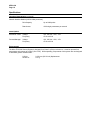
The HM serves as a system-wide,
multi-use mass storage device.
This stored information is available
to any module on the TPLCN.
Information from processconnected devices can be stored
on the HM. The major elements of
the HM are shown in Figure 7.
WINCHESTER
DISK DRIVE
DISK STORAGE
MANAGEMENT
TWISTED PAIR LOCAL CONTROL NETWORK
1132
History Module
The History Module (HM)
communicates with other modules
Figure 7 — History Module Elements
MT03-420
Page 14
Active system files
• Graphic display abstracts
• Database checkpoints
• User files (e.g., CL)
• System configuration files
Static system files
• Software images
On Process Analysis program
• Maintenance aid
The HM is loaded, configured, and
initialized at the factory with the
standard Enhanced Micro
TDC 3000 volumes, directories,
and database. A prebuilt Network
Configuration File (NCF) is
supplied with the system. The
user can reconfigure the NCF to
suit his specific needs.
Continuous Process History
The HM is configured (in the NCF)
to store continuous history. The
values for 10 units (with 10 groups
per unit) are collected once a
minute and used to calculate
various types of averages.
The following base averages are
maintained:
•
•
•
•
Hourly averages for 1 week
Shift averages for 1 week
Daily averages for 1 month
Monthly averages for 1 year
Discrete data samples
("snapshots") and user averages
(over 6 minutes periods) are
computed and saved for 168
hours (1 week) for "snapshot"
data, and 336 hours (2 weeks) for
user averages.
Event History
Event history is also stored in the
HM. Event history consists of
process alarms, operator process
and system changes, operator
messages, and the system error
and maintenance journals. The
last 1400 events are kept for each
of the 10 units.
Display Abstracts
Space is allocated to store display
abstracts (everything except the
dynamic information) on the HM.
Loadable Software Images
Software images are stored on the
HM instead of a cartridge disk to
facilitate loading.
Database
Information on the data content of
the modules on the TPLCN and
UCN is stored in the HM. It can be
quickly uploaded (checkpointed)
and downloaded using simple
operator commands. This
database storage is used each
time a point-owner module (AM,
NIM, PM) is reloaded.
On Process Analysis Program
This program performs periodic
analysis of the accumulated errors
for each TPLCN module and
issues recommendations for
hardware replacement if a
predefined error-frequency limit is
exceeded.
These recommendations are
displayed on the US and entered
in the maintenance journal.
System Peripherals
• Touchscreens or Trackballs:
Touchscreens or trackballs are
optional peripherals that allow
the user to "point" to areas on a
display and select operations to
be performed. (Without a
touchscreen or trackball, the
user must use the directional
arrows on the keyboard to
navigate across the screen.)
• Engineer's Keyboard: An
additional engineer’s keyboard
is an option on any added US.
• Printer: A second printer is an
option on an Enhanced Micro
TDC 3000 with two or more
USs.
Optional TPLCN Nodes
Additional TPLCN nodes (up to
the maximum total of eight nodes
per Enhanced TDC 3000 System)
may be added to the towers.
The following system expansion
nodes are available:
• Universal Station: Provides
additional windows to the
process. Up to a total of four
USs maybe installed in an
Enhanced Micro TDC 3000
system. The additional USs can
support either "Operator"
personality or "Universal"
personality.
• Redundant Network Interface
Module (NIM): Provides a
second path to the process
devices in the event of a primary
failure.
• Computer Gateway: Provides a
path to a host computer.
• Plant Network Module: A
dedicated interface to a Digital
VAX or AlphaAXP host
computer, supporting
bidirectional data transfer
between the Enhanced Micro
TDC system and OpenVMSbased applications.
• Network Gateway: Enables an
Enhanced Micro TDC 3000
system to be linked to either
another Enhanced Micro
TDC 3000 or a TDC 3000X
LCN at a different location.
Bidirectional transfer of data
between the Enhanced Micro
TDC 3000 system and the
other system allows plantwide
information to be integrated and
accessed at a single window.
Communications are effected
via carrierband or fiberoptic links
(optional), with a Network
Gateway at each end of the link.
MT03-420
Page 15
• Programmable Logic Controller
Gateway: Provides a path to
one or more Programmable
Logic Controllers.
References
See the following Specification
and Technical Data publications:
AM03-400 - Application Module
CG03-400 - Computer Gateway
HM03-400 - History Module
LC03-400 - Local Control Network
PL03-400 - Programmable Logic
Controller Gateway
PM03-400 - Process Manager
US03-400 - Universal Station
LM03-400 - Logic Manager
See also MT11-420 (8-Node
Enhanced Micro TDC 3000
User’s Manual) and MT13-420
(8-Node Multinode Module
Service).
MT03-420
Page 16
Specifications
Physical Characteristics
Approximate Dimensions
Approximate Weight
Electronics Tower
(each)
Height
Width
Depth
72 cm (28.5")
32 cm (12 .5")
58 cm (22.8")
45 kg (100 lb)
Printer
Height
Width
Depth
17 cm (6.7")
62 cm (24.2")
31 cm (12.2")
14 kg (30 lb)
Color Monitor (21")
Height
Width
Depth
47 cm (18.5")
49 cm (19.4")
54 cm (21.1")
33 kg (73 lb) net
Advanced Process Manager
(Single-Access)
Height
Width
Depth
201 cm (79")
80 cm (31.5")
50 cm (19.7")
113 kg (250 lb) max.
Twisted Pair Local Control Network
Universal Control Network
Type
Length
Modules
RS-485 Twisted Pair (noncoaxial)
Between towers; 1.5 m (5 ft) standard; 10 M (33 ft)
optional (max.)
Up to 4 modules per tower (8 max.)
Type
Trunk Cable
RG-11, quad shield with inner
and outer foil and braid shields,
and PVC flame-retardant jacket
Drop Cable
RG-6 quad shield
Trunk Cable
Depends on number of drops
(refer to Site Planning/Universal
Control Network manual)
Drop Cable
Up to 50 meters
Length
Operating Characteristics
Universal Station (K2LCN-4 Mw processor)*
* K2LCN-4 Mw processors are standard on the Universal Stations supplied with the base system models. This
supports the "Universal" personality. Universal Stations with K2LCN-3 Mw processors that support only the
"Operator" personality are also available as a system expansion option.
Display Type
Call-up Times (typical)
System Monitoring/
Maintenance Displays
Group
Detail
Trends
Alarm Summary
Status
Point Summary
1.5-2 seconds
4-6 seconds
8-20 seconds
1-2 seconds (first value update in 10 secs)
1-3 seconds
2-20 seconds
Graphic History
(100-150 parameters)
US-resident
HM-resident
3-5 seconds
3-6 seconds
Primary Operating Displays
Display Capacities
Point Detail Display: All points in the system
Operating Group Display: 450 (400 standard + 50 Process Module)
MT03-420
Page 17
Specifications
Operating Characteristics (continued)
Universal Station (continued)
Display Capacities
Graphic Display
Limited only by available storage capacity, including US, HM, and
Cartridge disks.
Color Monitor
Resolution
1600 x 1280 pixels (noninterlaced)
Cartridge Disk Drive
(5 1/4 in. disk)
Memory Capacity
Data Transfer Rate
21,417,894 bytes
500 kbits per second
Printer
Desk top, 132 column, tractor feed (continuous sheet) dot matrix
printer, 250 cps
Application Module (K2LCN-2 Mw or K2LCN-8 Mw processor, depending on base system model purchased).
Point Processing Capacity
Up to 120 data points per second, depending on point type.
Data Point Capacity
Varies widely with point type and memory usage.
See Engineer’s Reference Manual for details.
Point Scheduling Capacity
Fast Processing
1 sec, 2 sec, 5 sec, 10 sec, 15 sec, 30 sec,
1 min, 2 min, and on demand
Slow Processing
1 min, 2 min, 5 min, 10 min, 15 min, 30 min,
1 hr 8 hr, 12 hr, 24 hr, and on demand
History Module (K2LCN-2 Mw processor)
Memory Capacity
445 megabytes (exactly 443.486 megabytes)*
(* 1 megabyte = 1,024 kilobytes = 1,048,576 bytes)
Data Transfer Rate
4.84 megabytes per second
Average Latency Time
6.61 msec
Average Seek Time`
11.25 msec (typical)
Watts (maximum)
7 Watts
Non recoverable Read Errors
<1 per 1014 bits transferred
Error Detection and Recovery
Retries, generation, and checking of checkcodes, correction of burst
errors of up to 48 bits.
Seek Error Rate
<1 per 107 physical seeks
Unrecoverable Error Rate
One in 1012 bits transferred or less
MT03-420
Page 18
Specifications
Operating Characteristics (continued)
Network Interface Module (K2LCN-2 Mw processor)
Point Capacity
Up to 8000 points
Data Access
1200 single parameters per second
Electronics Tower
Voltage
Frequency
120, 240 Vac +10%, -15%
47 Hz to 63 Hz
Process Manager
Voltage
Frequency
120, 240 Vac +10%, -15%
47 Hz to 63 Hz
Power Options
Environmental
The Micro TDC 3000 Control System is designed for a Class C (office) environment. It must be operated in a
temperature environment of 0°-45°C (32°-113°F). While operating, components of this system are not designed
to withstand greater vibrations than:
5-22 Hz
22-500 Hz
0.254 mm (0.010 inch) displacement
0.25 g
MT03-420
Page 19
Copyright, Trademarks, and Notices
The following are trademarks of Honeywell Inc.:
TDC 3000X system
The following are trademarks of their respective companies or organizations:
Modbus
Allen-Bradley
All other brand or product names appearing herein are trademarks of their respective companies or
organizations.
MT03-420
Page 20
While this information is presented in good faith and believed to be accurate, Honeywell disclaims the implied warranties of merchantability and fitness for a particular purpose and
makes no express warranties except as may be stated in its written agreement with and for its customer.
In no event is Honeywell liable to anyone for any indirect, special or consequential damages. The information and specifications in this document are subject to change without notice.
Printed in U.S.A. — © Copyright 1992 - Honeywell Inc.