1
Assembly Preparation and Procedures:
1) Important: identify all parts on parts list
before proceeding. If you are having
difficulties in identifying the parts
visually, suggest that you use a multimeter
that can measure capacitance, resistance,
voltage. Measure the components
accordingly.
2) Suggestion: simulate board assembly by
placing the components in their actual
place on the picture assembly, then
transfer the components to the actual
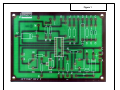
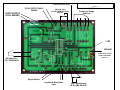
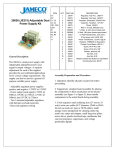
board for soldering assembly. (see figure
1 for scanned board assembly)
3) Tools required: small soldering iron 27W
to 35W; resin core solder (0.03" diameter
with SN60 or SN63); small sponge (water
dampened) for cleaning solder tip; small
wire cutter/stripper; small long nose pliers;
small screw driver; multimeter for
measuring voltage, capacitance, and
resistance.
Soldering Tips:
1) Feed the solder to the crack between the
iron tip and the solder pad next to the
component lead.
2) Leaving the iron tip too long on a pad will
cause the pad to life, as well as damage the
component. Allow approximately 2
seconds per solder joint.
3) Using too much solder can cause the
solder to bridge across traces and pads.
4) Keep iron tip clean by wiping iron across
water dampened sponge -- frequently.
Assembly Instructions:
READ ALL INSTRUCTIONS BEFORE
STARTING!!!
Before assembly, determine if a split power supply
or a single power supply will be used, as
placement of R12 potentiometer will change (with
an addition of a jumper wire across the output
voltage nodes - please see figure 3 for single
power supply and figure 4 for split power supply.
Printed wiring board assembly
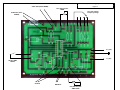
1) Start the board assembly by placing the
printed circuit board to the position shown
on figure 1 and figure 2
2) Insert resistors R1 through R8 into the
board. Observe the color code of each
resistor as you install them (color code is
stated in the parts list for each resistor. If
uncertain, measure the resistors with your
multimeter and label them accordingly).
Bend the leads at the bottom of the PCB
board to contain the resistors, solder and
clip excess leads.
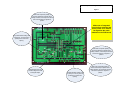
3) Insert IC1 into board. Be sure that the
notch at the end of the IC is located
properly as shown for pin number 1
identification (see figure 2).
4) Insert potentiometers (adjustable resistors)
R9, R10, and R11 as shown (see figure 2).
Resistors R9 and R10 will require
spreading of the leads to match the hole
spacing on the board. R11 requires
matching the adjustment knob aligned to
the small rectangular shape (see figure 2).
Solder leads.
5) Insert capacitors C1, C2, and C7 into the
board. Note that the leads are polarized
and must be placed as shown (see figure
2). Bend leads at the bottom of the PCB to
contain capacitors, solder, and clip excess
leads.
6) Insert capacitors C3, C4, C5, and C6. The
capacitance values are marked on the