1
SAFETY SYMBOLS
NOTE: Starting in this section and continuing
throughout remainder of manual, references may be
made to a two-stage hone head (GHTS). These
features can be enabled as an option. Please contact
your Sunnen representative for more information.
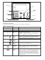
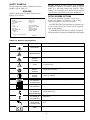
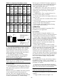
For a description of safety symbols used on this
machine refer to Table 2-2.
SCREENS
Operator Interface and Control Station Screen
options are as follows:
SETUP SCREEN OPTIONS
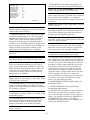
This screen will allow operator to enter Setup
options (see Figure 2-3). Below is a list of items
and a description of each item on screen.
SETUP SCREEN
SAVE SETUPS
COOLANT: AUTO
STROKE LENGTH CALCULATOR
SPARK OUT TIME:
JOG: STROKER
STAGE 1: 0
UNITS: IN.
CYCLE:
1. SAVED SETUPS: This option allows operator to go
to save setups screen. This screen will be explained
later in this manual.
DISPLAY: BORE PROFILE
STAGE 1: SIZE
BORE PROFILE GAIN: NORMAL
SETUP: A
TOOL: GHSS
CLEAR CYCLE COUNT: NO
SPEED AND DIMENSIONS
SERIAL PORT TRANSFERS
AUTO DWELL:
LANGUAGE: ENGLISH
2. STROKE LENGTH CALCULATOR: This option
allows operator to calculate recommended stroke length.
STAGE 1: OFF
PRESS F3 TO GO TO THE RUN SCREEN
RUN SCREEN
FIGURE 2-3, Setup Screen
TABLE 2-2, Machine Safety Symbols
SYMBOL
DESCRIPTION
CAUTION
ELECTRICAL
CAUTION
MOVING PARTS
FUNCTION
Warns that an electrical hazard exists.
Warns that a finger hazard exists.
CAUTION
DO NOT
HIT HEAD
Warns of possible head injury from move arm.
WARNING
LIGHT
Warns that power must be OFF when belt guard is opened,
to prevent injury.
WARNING
SAFETY
GLASSES
Warns that safety glasses should be worn at all times when
operating this machine.
CAUTION
DO NOT
TOUCH
Warns that a finger hazard exists. Do not touch while
stroker is operating.
DIRECTION
OF ROTATION
TO RAISE PART
Indicates direction to turn elevating crank to raise cradle.
DIRECTION
OF ROTATION
Indicate the direction that motor or part is rotating.
DIRECTION
OF ROTATION
INCREASE/DECREASE
Direction of rotation to increase and decrease the Stroke
Length Adjustment.
DIRECTION
OF ROTATION
LOCK/UNLOCK
Direction of rotation to lock and unlock the Stroke Length
Adjustment.
DIRECTION
TO INCREASE
COOLANT FLOW
Indicates to turn counter clockwise to increase the coolant
flow.
“CE”
LABEL
Indicates that machine is in “CE” compliance.
9