1
MOUNT CONTROL SYSTEM - CONTROL SYSTEM DESIGN DESCRIPTION
implement the encoder (see Section 3.2) and servo algorithms. The set up of these
cards is quite complex and is described in detail in reference [11]. Note that the
default setting for the servo rate in PMAC is approximately 2 kHz. Unless a reduction
in servo rate is required by another system (e.g. the encoders), and the reduction is
proved, by simulation, to have no effect upon servo performance, the sampling
frequency will be not be changed from the default value.
3.1.3.2. Servo Specification
The error budget, after tip/tilt correction, agreed with the IGPO is 20 milli-arcseconds
RMS, on axis, at zenith. This increases with zenith distance, Z, according to the
following equation:
1 + sin 2 (Z )
E = 0.02
Where E is the permitted error, on axis, in arcseconds.
The on axis error is calculated from individual axis errors by using the following
equation:
E E 2 + [E A
ET =
sin(Z )]
2
Where: ET is total on axis error.
EA is total azimuth error.
EE is total elevation error.
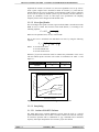
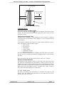
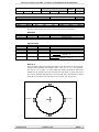
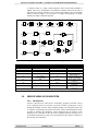
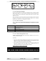
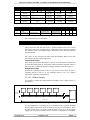
Reference [8] uses the non-linear model to estimate the performance of the servos
with and without tip/tilt correction. The results are summarised in Table 3.1 and
Figure 3.1.
RMS milli-arcseconds
Without Tip/Tilt
With Tip/Tilt
Azimuth
55
23
Elevation
27.7
0.05
Table 3.1 - Summary Of Error Predictions
70
Errors Without Tip/Tilt
60
Milli-arcseconds
50
40
Error Budget
30
20
10
0
0
Errors With Tip/Tilt
20
40
60
Zenith Distance (Degrees)
80
100
Figure 3.1 - On Axis Errors For The Range Of Zenith Distance
3.1.3.3. Interfacing
3.1.3.3.1. Interface With MCS Software
The MCS shall receive position demands at 20 Hz from the TCS, or a one-off
position demand from the TCS or MEC. The MCS software will cause the telescope
to track these positions with a combination of “jog” commands and a calculated
trajectory based upon interpolation. See reference [2] for more details.
ISSUE : 3
14 January 1997
PAGE 15 of 79