1
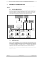
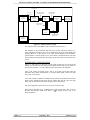
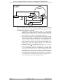
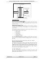
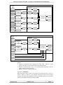
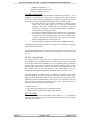
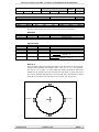
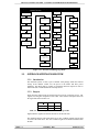
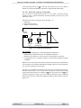
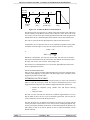
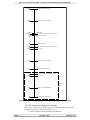
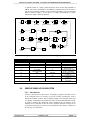
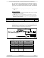
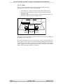
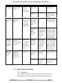
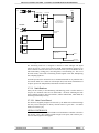
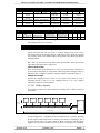
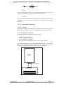
MOUNT CONTROL SYSTEM - CONTROL SYSTEM DESIGN DESCRIPTION
3.6.3.2. Limits
Figure 3.33 shows, schematically, the interface between the main axis and an
associated wrap. Three levels of limit can be identified:
1. MCS Wrap Limit - Triggered from the LVDT reading within the MCS.
2. Interlock System Wrap Limit - Triggered by micro-switches, read by the
Interlock System.
3. Drag Plates - Physical plates that provide a mechanical link between the axis
and wrap, so that the wrap can be dragged around.
AXIS
Drag Plates
LVDT
d3
WRAP
Interlock
System
Limit
MCS Limit
Interlock
System
Limit
Figure 3.33 - Position Of Cable Wrap Limits
The distance, d3, between the two drag plates is limited by the span of the LVDT and
the amount of ‘give’ in the cables.
The MCS shall disable both the service-wrap drive and the associated main drive
upon reaching a MCS wrap limit. The effect of hitting an Interlock System limit will
be defined by the GIS. Table 3.13 shows the various limit conditions with required
actions, suggested recovery methods and possible causes. The safety of the outcome
and the effects of the fault persisting are also shown.
ISSUE : 3
14 January 1997
PAGE 57 of 79