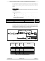
1
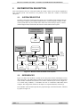
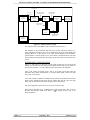
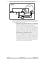
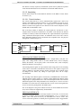
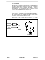
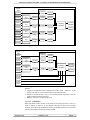
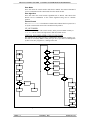
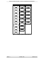
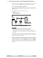
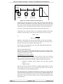
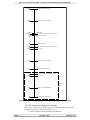
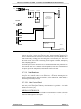
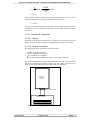
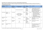
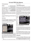
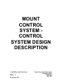
MOUNT CONTROL SYSTEM - CONTROL SYSTEM DESIGN DESCRIPTION
L=
bTR
T
100 =
304950
500 103
100
L = 61 %
This is within limits for CANbus, which can theoretically operate at close to 100%
bus load. If polling for each message is added, the bus load rises to:
L = 105 %
This clearly exceeds bus capacity, and therefore it is not possible to run six nodes on
a 500kbit/sec. bus at a constant 25Hz message rate. Five nodes could be run at this
rate however.
3.7.3.5. Enclosure & Connections
3.7.3.5.1. Housing
Each node will be housed in an ABS box of a similar type to that used by the Axial
Support nodes. It will have a conductive coating applied internally to reduce EMI.
3.7.3.5.2. Physical Connections
The following physical connections are made to the node.
• CANbus (screened, twisted pair)
• 120VAC single-phase mains power
•
12V external DC in (if required)
• Sensor and transducer connections (via two 37-way D-type connectors)
The sensors and transducers are not connected directly to the node box itself, but are
routed via a breakout box as shown in Figure 3.39. This enables a node box to be
easily removed without having to break a large number of connections.
Monitoring &
Metrology
Node box
2 x 37-way D-type connectors
Connector breakout box
Figure 3.39 - Connecting sensors via a breakout box
PAGE 68 of 79
14 January 1997
ISSUE : 3