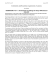
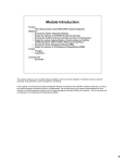
1
Digital Time/Date Display Clocks
DTD-5230, DTD-5231, and DTD-5233
Installation and Operation Manual
Edition B
175-000025-00
DTD-5230,
DTD-5231, and
DTD-5233
Digital Time/Date Display Clocks
Installation and Operation Manual
Edition B
October 2006
Trademarks and Copyrights
CCS, CCS CoPilot, CCS Navigator, CCS Pilot, Command Control System,
CineTone, CinePhase, CineSound, DigiBus, DigiPeek, Digital Glue,
DigiWorks, DTV Glue, EventWORKS, EZ HD, Genesis, HDTV Glue,
Image Q, Icon, IconLogo, IconMaster, IconMaster Nav, IconSet, Icon
Station, Inca, Inca Station, InfoCaster, Inscriber, Inscriber CG—FX,
Integrator, LeFont, Leitch, LogoMotion, MediaFile, MIX BOX, NEO, the
NEO design, NEOSCOPE, NewsFlash, Nexio, Opus, Panacea,
PanelMAPPER, Platinum, Portal, PROM-Slide, RouterMAPPER,
RouterWORKS, Signal Quality Manager, SpyderWeb, SuiteView,
TitleMotion, UNIFRAME, Velocity, VelocityHD, VideoCarte, Videotek,
and X75 are trademarks of the Harris Corporation, which may be registered
in the United States, Canada, and/or other countries. All other trademarks
are the property of their respective owners.
Copyright 2006, Harris Corporation. All rights reserved. This publication
supersedes all previous releases. Printed in Canada.
Warranty Information
The Limited Warranty Policy provides a complete description of your
warranty coverage, limitations, and exclusions, as well as procedures
for obtaining warranty service. To view the complete warranty, visit
www.broadcast.harris.com/leitch.
Contents
Preface
Manual Information .................................................................................v
Purpose ..............................................................................................v
Audience ...........................................................................................v
Revision History ...............................................................................v
Writing Conventions ....................................................................... vi
Obtaining Documents ..................................................................... vi
Unpacking/Shipping Information ......................................................... vii
Unpacking a Product ...................................................................... vii
Product Servicing ........................................................................... vii
Returning a Product ....................................................................... vii
Restriction on Hazardous Substances (RoHS) Compliance ................ viii
Waste from Electrical and Electronic Equipment (WEEE) Compliance ix
Safety .......................................................................................................x
Safety Terms and Symbols in this Manual .......................................x
Chapter 1: Introducing the DTD-523X Clock Series
Overview ..................................................................................................1
Available Models ..............................................................................2
Chapter 2: Installing the DTD-523x
Overview ..................................................................................................3
Installation Requirements ........................................................................4
Rack Mounting .................................................................................4
Cooling ..............................................................................................4
Rear Panel Installation .............................................................................5
Input Switch Functions .....................................................................5
Power Supply ...........................................................................................5
DTD-5230, DTD-5231, and DTD-5233 Installation and Operation Manual
iii
Contents
Chapter 3: Operation
Overview ................................................................................................. 7
Setting the Control Mode ........................................................................ 8
Clock Mode ...................................................................................... 9
Timecode Reader Mode ................................................................. 10
Secondary Reference Mode ........................................................... 10
Auxiliary Offset ............................................................................. 11
Date Display ................................................................................... 12
Timecode Generator Mode ............................................................ 12
Brightness Adjustment ................................................................... 13
Clock Setting ......................................................................................... 14
Manual Time Setting ...................................................................... 14
Local Offset Programming ............................................................. 15
Chapter 4: Specifications
Overview ............................................................................................... 17
Input Specifications ........................................................................ 18
Output Specifications ..................................................................... 18
Electrical Specifications ................................................................. 18
Time Base Specifications ............................................................... 19
Control Specifications .................................................................... 19
Mechanical Specifications ............................................................. 20
Appendix A: Servicing Instructions
Overview ............................................................................................... 21
Fuse Replacement ................................................................................. 22
Replacement Procedure .................................................................. 22
Battery Replacement ............................................................................. 23
Battery Use Warnings .................................................................... 23
Replacement Procedure .................................................................. 24
Voltage Selection .................................................................................. 25
Index
Keywords .............................................................................................. 27
iv
DTD-5230, DTD-5231, and DTD-5233 Installation and Operation Manual
Preface
Manual Information
Purpose
This manual details the features, installation, operation, maintenance,
and specifications for DTD-5230, DTD-5231, and DTD-5233 Digital
Time/Date Display Clocks.
Audience
This manual is written for engineers, technicians, and operators
responsible for installation, setup, maintenance, and/or operation of
DTD-5230, DTD-5231, and DTD-5233 Digital Time/Date Display
Clocks.
Revision History
Table P-1. Revision History of Manual
Edition
Date
Comments
A
March 2002
Full release
B
October 2006
Manual reformatted and updated
DTD-5230, DTD-5231, and DTD-5233 Installation and Operation Manual
v
Preface
Writing Conventions
To enhance your understanding, the authors of this manual have
adhered to the following text conventions:
Table P-2. Writing Conventions
Term or
Convention
Description
Bold
Indicates dialog boxes, property sheets, fields, buttons,
check boxes, list boxes, combo boxes, menus,
submenus, windows, lists, and selection names
Italics
Indicates E-mail addresses, the names of books or
publications, and the first instances of new terms and
specialized words that need emphasis
CAPS
Indicates a specific key on the keyboard, such as
ENTER, TAB, CTRL, ALT, or DELETE
Code
Indicates variables or command-line entries, such as a
DOS entry or something you type into a field
>
Indicates the direction of navigation through a hierarchy
of menus and windows
hyperlink
Indicates a jump to another location within the
electronic document or elsewhere
Internet address
Indicates a jump to a Web site or URL
Note
Indicates important information that helps to avoid and
troubleshoot problems
Obtaining Documents
Product support documents can be viewed or downloaded from our
Web site at www.broadcast.harris.com/leitch (go to Support>
Documentation). Alternatively, contact your Customer Service
representative to request a document.
vi
DTD-5230, DTD-5231, and DTD-5233 Installation and Operation Manual
Preface
Unpacking/Shipping Information
Unpacking a Product
This product was carefully inspected, tested, and calibrated before
shipment to ensure years of stable and trouble-free service.
1. Check equipment for any visible damage that may have occurred
during transit.
2. Confirm that you have received all items listed on the packing list.
3. Contact your dealer if any item on the packing list is missing.
4. Contact the carrier if any item is damaged.
5. Remove all packaging material from the product and its associated
components before you install the unit.
Keep at least one set of original packaging, in the event that you need to
return a product for servicing.
Product Servicing
DTD-5230, DTD-5231, and DTD-5233 Digital Time/Date Display
Clocks are not designed for field servicing. All upgrades, modifications,
or repairs require you to return the product to the Customer Service
center.
Returning a Product
In the unlikely event that your product fails to operate properly, please
contact Customer Service to obtain a Return Authorization (RA)
number, then send the unit back for servicing.
Keep at least one set of original packaging in the event that a product
needs to be returned for service. If the original package is not available,
you can supply your own packaging as long as it meets the following
criteria:
•
The packaging must be able to withstand the product’s weight.
•
The product must be held rigid within the packaging.
•
There must be at least 2 in. (5 cm) of space between the product and
the container.
•
The corners of the product must be protected.
DTD-5230, DTD-5231, and DTD-5233 Installation and Operation Manual
vii
Preface
Ship products back to us for servicing prepaid and, if possible, in the
original packaging material. If the product is still within the warranty
period, we will return the product prepaid after servicing.
Restriction on Hazardous Substances (RoHS)
Compliance
Directive 2002/95/EC—commonly known as the European Union (EU)
Restriction on Hazardous Substances (RoHS)—sets limits on the use of
certain substances found in electrical and electronic equipment. The
intent of this legislation is to reduce the amount of hazardous chemicals
that may leach out of landfill sites or otherwise contaminate the
environment during end-of-life recycling. The Directive takes effect on
July 1, 2006, and it refers to the following hazardous substances:
•
Lead (Pb)
•
Mercury (Hg)
•
Cadmium (Cd)
•
Hexavalent Chromium (Cr-V1)
•
Polybrominated Biphenyls (PBB)
•
Polybrominated Diphenyl Ethers (PBDE)
According to this EU Directive, all products sold in the European Union
will be fully RoHS-compliant and “lead-free.” (See our Web site,
www.broadcast.harris.com/leitch, for more information on dates and
deadlines for compliance.) Spare parts supplied for the repair and
upgrade of equipment sold before July 1, 2006 are exempt from the
legislation. Equipment that complies with the EU directive will be
marked with a RoHS-compliant emblem, as shown in Figure P-1.
Figure P-1. RoHS Compliance Emblem
viii
DTD-5230, DTD-5231, and DTD-5233 Installation and Operation Manual
Preface
Waste from Electrical and Electronic
Equipment (WEEE) Compliance
The European Union (EU) Directive 2002/96/EC on Waste from
Electrical and Electronic Equipment (WEEE) deals with the collection,
treatment, recovery, and recycling of electrical and electronic waste
products. The objective of the WEEE Directive is to assign the
responsibility for the disposal of associated hazardous waste to either
the producers or users of these products. Effective August 13, 2005,
producers or users will be required to recycle electrical and electronic
equipment at end of its useful life, and may not dispose of the
equipment in landfills or by using other unapproved methods. (Some
EU member states may have different deadlines.)
In accordance with this EU Directive, companies selling electric or
electronic devices in the EU will affix labels indicating that such
products must be properly recycled. (See our Web site,
www.broadcast.harris.com/leitch, for more information on dates and
deadlines for compliance.) Contact your local sales representative for
information on returning these products for recycling. Equipment that
complies with the EU directive will be marked with a WEEE-compliant
emblem, as shown in Figure P-2.
Figure P-2. WEEE Compliance Emblem
DTD-5230, DTD-5231, and DTD-5233 Installation and Operation Manual
ix
Preface
Safety
Carefully review all safety precautions to avoid injury and prevent
damage to this product or any products connected to it. If this product is
rack-mountable, it should be mounted in an appropriate rack using the
rack-mounting positions and rear support guides provided. It is
recommended that each frame be connected to a separate electrical
circuit for protection against circuit overloading. If this product relies
on forced air cooling, it is recommended that all obstructions to the air
flow be removed prior to mounting the frame in the rack.
If this product has a provision for external earth grounding, it is
recommended that the frame be grounded to earth via the protective
earth ground on the rear panel.
IMPORTANT! Only qualified personnel should perform service
procedures.
Safety Terms and Symbols in this Manual
WARNING
Statements identifying conditions or
practices that may result in personal injury
or loss of life. High voltage is present.
CAUTION
Statements identifying conditions or
practices that can result in damage to the
equipment or other property.
x
DTD-5230, DTD-5231, and DTD-5233 Installation and Operation Manual
Chapter 1
Introducing the DTD-523X Clock Series
Overview
The DTD-523x series of digital time/date display clocks (including the
DTD-5230, DTD-5231, and DTD-5233) replaces the following clocks:
•
DTD-5200
•
DTD-5210
•
DTD-5203
Note
Except where noted, the term “DTD-523x” is used in this manual to
refer to the DTD-5230, DTD-5231, and DTD-5233 digital time/date
display clocks.
The DTD-523x series are digitally controlled, self-setting clocks. They
operate in one of two modes: Stand-alone mode via power line
frequency or internal crystal, or with an SMPTE or EBU serial timecode
input as either a clock or a timecode reader.
When provided with an SMPTE or EBU timecode source, the
DTD-523x series of clocks are instantly self-setting. In the event of a
power failure, the DTD-523x clocks maintain the correct time internally
via a battery-backed timekeeping memory. If power is restored without
timecode, the clocks will self-set to the correct time as maintained by
the battery backup, and then continue to operate on internal crystal or
power-line time base.
DTD-5230, DTD-5231, and DTD-5233 Installation and Operation Manual
1
Chapter 1: Introducing the DTD-523X Clock Series
DTD-523x clocks automatically decode either SMPTE or EBU
timecode inputs. Additionally, these clocks function as timecode
generators when operated from their internal crystals. Either SMPTE or
EBU timecode can be generated and used to drive other clocks.
When driven from the MTG-3901 Master Time Generator or
CSD-3901/3902 Clock System Driver, DTD-523x clocks are
compatible with a user-defined auxiliary time offset and date. Some
abilities are as follows:
•
Local offset can also be programmed up to 23:59:59.
•
Time display can be either 12- or 24-hour format, and can display
HH:MM:SS or MM:SS.FF.
•
Dates can be displayed as month:day:year (MM:DD:YY) or
day:month:year (DD:MM:YY).
In the event of a timecode input failure, the colon LEDs flash at the rate
of twice per second. DTD-523x clocks then automatically switch to the
user-selected secondary time base, either power line frequency or
internal crystal. (The power line frequency is automatically determined
during power-up.)
If timecode operation is not required, DTD-523x clocks may be set to
use the secondary time base permanently, and the colon LEDs will not
flash.
If operated as a timecode reader display, DTD-523x clocks continually
track the input code, and then stop when the input fails. The colon
LEDs extinguish when timecode is absent in this mode.
The digital time/date display clocks are available in rack-mount (1 RU)
or desktop versions.
Available Models
The following digital time/date display clock models are available:
2
•
DTD-5230
Digital Time Display (0.8 in./20.3 mm display)
•
DTD-5231
Digital Time Display, desktop, time, or date
•
DTD-5233
Digital Time Display with dual time or date
DTD-5230, DTD-5231, and DTD-5233 Installation and Operation Manual
Chapter 2
Installing the DTD-523x
Overview
This chapter exaplaind the installation process, including unpacking
your equipment, ensuring a safe installation and operating environment,
and connecting a DTD-523x clock.
Note
Except where noted, the term “DTD-523x” is used in this manual to
refer to the DTD-5230, DTD-5231, and DTD-5233 digital time/date
display clocks.
The DTD-523x digital time/date display series of clocks are carefully
inspected, tested, and calibrated before shipment to ensure years of
stable and trouble-free service. Please check the equipment for any
visible damage, which may have been caused during transit.
The following topics are found in this chapter:
•
“Installation Requirements” on page 4
•
“Rear Panel Installation” on page 5
•
“Power Supply” on page 5
DTD-5230, DTD-5231, and DTD-5233 Installation and Operation Manual
3
Chapter 2: Installing the DTD-523x
Installation Requirements
Rack Mounting
The DTD-5230 and DTD-5233 require a standard 1RU rack space.
Dimensions for these rack-mounted clocks are as follows:
Front Panel
Height
1.75 in. (4.4 cm)
Width
19 in. (48.3 cm)
Depth
6 in. (15.2 cm)
PCB Box
Height
1.58 in. (4.01 cm)
Width
8.14 in. (20.68 cm)
Depth
6.5 in. (16.61 cm)
Note
The DTD-5231 is a desktop model and does not require rack.
Cooling
The equipment is designed to operate in an ambient temperature range
of 0° to +50° C. No special cooling arrangements are necessary, but
care should be taken to prevent excessive ambient heat rise in closed,
unventilated equipment racks.
4
DTD-5230, DTD-5231, and DTD-5233 Installation and Operation Manual
Chapter 2: Installing the DTD-523x
Rear Panel Installation
The rear panel has two connectors (see Figure 3-1 on page 3-8).
Depending on the configuration, these connectors either accept or
output serial timecode (SMPTE or EBU). All clocks are shipped
configured for timecode input (slave) operation, unless otherwise
specified when ordering. A label indicates whether the clock is in
Master or Slave configuration.
A standard AC power connector and cord are included.
Input Switch Functions
The DIP switch at the rear of the DTD-523x unit is used to configure
many of the operational parameters of the unit. All switches enable their
corresponding function when in the up position.
See “Setting the Control Mode” on page 8 for details on DIP switch
operation.
Power Supply
The power consumption of the DTD-523x is 6 W at nominally
100-120/200-240 VAC (0.25/0.15 A max.), 50/60 Hz. In order that the
unit operates with maximum stability, it is recommended that the power
be applied 24 hours a day.
DTD-5230, DTD-5231, and DTD-5233 Installation and Operation Manual
5
Chapter 2: Installing the DTD-523x
6
DTD-5230, DTD-5231, and DTD-5233 Installation and Operation Manual
Chapter 3
Operation
Overview
This chapter explains how to operate the DTD-523x series of digital
time/date display clocks.
The following topics are found in this chapter:
•
“Setting the Control Mode” on page 8
•
“Clock Setting” on page 14
Note
Except where noted, the term “DTD-523x” is used in this manual to
refer to the DTD-5230, DTD-5231, and DTD-5233 digital time/date
display clocks.
DTD-5230, DTD-5231, and DTD-5233 Installation and Operation Manual
7
Chapter 3: Operation
Setting the Control Mode
DTD-523x control modes are selected with rear panel DIP switches.
These switches are described in the table below. Each mode is described
in the pages that follow.
Switch
Closed Position (Up)
Opened Position (Down)
SW1-1
Display format
12-hour (HH:MM:SS)
24-hour (HH:SS:FF)
SW1-2
Normal and secondary
reference
Normal
Run on secondary
(Date if code present)
SW1-3
Auxiliary offset
Normal
Use auxiliary offset
(MTG-3901, CSD-3901/3902
required)
SW1-4
Secondary reference
Internal—Secondary
reference
Line
SW1-5
Timecode output format
SMPTE—Output format
EBU
SW1-6
Clock mode
Clock
Timecode
1-1
1-2
1-3
1-4
1-5
1-6
Detail of DIP Switches
Closed
Opened
DTD-523x Rear Panel
100-120
200-240
SW1~SW6
100-120 VAC/200-240 VAC
50/60 Hz
0.25/0.15 A max.
RESET
INC
DEC
TIMECODE
GND
MANUAL
SET
TIMECODE
IN/OUT
Figure 3-1. DTD-523x DIP Switches
8
DTD-5230, DTD-5231, and DTD-5233 Installation and Operation Manual
Chapter 3: Operation
Clock Mode
To operate the DTD-523x as a timecode reading clock, the DIP
switch 1-6 must be in the Clock (closed) position.
No time setting is required when input timecode is provided to the
DTD-523x clock.
Once a valid SMPTE/EBU timecode is detected, the clock instantly
self-sets.
Timecode Failure
If there is a failure or an error with the input timecode, the DTD-523x
switches to secondary reference as selected by DIP switch 1-4. Either
the clock’s own internal crystal or the power line frequency can be
selected as the secondary reference. Both provide the clock with a time
base during the absence of input timecode.
Note
Note that either a 50 Hz or 60 Hz power line frequency is suitable
for the time base since the clock automatically selects the correct
frequency available.
When signaling the failure of the input timecode, the colon LEDs on the
clock face flash at a rate of twice per second.
When correct timecode is reestablished, the clock self-sets to the new
time, and the colon LEDs stop flashing.
Timecode Error
If there is an error in the input timecode, the clock automatically
switches to the secondary reference, and the colon LEDs flash.
Time Display Format
When used in Clock Mode, the DTD-523x displays time in either
12- or 24-hour format. DIP switch 1-1 selects the display format:
•
12-hour: Closed position; uses the AM/PM LEDs
•
24-hour: Opened position; no LEDs
DTD-5230, DTD-5231, and DTD-5233 Installation and Operation Manual
9
Chapter 3: Operation
Timecode Reader Mode
To operate the DTD-523x strictly as a timecode display, DIP switch 1-6
must be in the Timecode (opened) position. When input SMPTE or
EBU timecode is present, the DTD-523x follows it directly: up, down,
or paused.
Timecode Failure
If there is a failure of input timecode, the following occurs:
•
Colon LEDs extinguish
•
Last valid time remains displayed
•
Input timecode does not switch to a secondary reference
Time Display Format
When used in Timecode Mode, the DTD-523x always displays time in
24-hour format without AM and PM indications. Using DIP switch 1-1,
the digits are configured for HH:MM:SS display or MM:SS.FF display.
Secondary Reference Mode
The DTD-523x runs as a standard clock when no input timecode is
provided. To operate the clock in this mode, make these settings:
•
Move the rear panel DIP switch 1-4 to select the time base: The
Internal (closed) position selects the clock’s internal crystal, while
the Line (opened) position selects the power line frequency (50Hz
or 60Hz).
•
Move DIP switch 1-6 to the Timecode (closed) position.
•
Move the rear panel DIP switch 1-2 to the Run on Secondary
(opened) position.
Note
The DTD-523x will still function without selecting Run On
Secondary. However, the colon LEDs will flash at the rate of twice
per second to indicate the absence of input timecode.
When in this position, the colon LEDs do NOT flash.
10
DTD-5230, DTD-5231, and DTD-5233 Installation and Operation Manual
Chapter 3: Operation
Setting Time
When operating in Secondary Reference Mode, the time must be set
manually using the rear panel set switches: MANUAL SET, INC, and
RESET DEC. See “Manual Time Setting” on page 14.
Power Failure
Once set, the correct time is maintained even in the event of a power
failure. Upon the return of external power, the clock automatically
self-sets to the correct time. The internal battery-backed timekeeping
function maintains time for up to four years in the absence of external
power.
Auxiliary Offset
DIP switch 1-3 allows access to a user-programmed, auxiliary offset
from the input timecode’s user bits. The timecode source must have the
ability to generate the correct information in the user bits. The
MTG-3901 Master Time Generator and CSD-3901/3902 Clock System
Driver are real-time, time-code source that can program such an offset
into the timecode’s user bits.
Offset Programming
The offset is programmed in 30-minute intervals, up to 23 hours and 30
minutes, using 6 bits of the timecode’s user bit space. The offset is
encoded using timecode bits 36, 37, 38, 52, 53, and 54. Bit 36 is the
least significant bit (LSB), while bit 54 is the most significant bit
(MSB).
When DIP switch 1-3 on the DTD-523x is in the Use Auxiliary Offset
(opened) position, the following occurs:
•
The auxiliary offset found in the input timecode’s user bits is added
to the input timecode, and the DTD-523x displays the total.
•
DIP switch 1-3 has no effect if no input timecode is available.
•
The offset is disregarded if the user bits are incorrectly
programmed.
•
A programmed local offset is still in effect while using the auxiliary
offset.
•
The local offset is totally transparent to the input timecode’s user bit
offset.
DTD-5230, DTD-5231, and DTD-5233 Installation and Operation Manual
11
Chapter 3: Operation
Loss of Timecode
If input timecode is removed while Use Auxiliary Offset is selected,
the clock retains the time with the offset added, not the original time.
Date Display
The date can be displayed by DTD-523x clocks when they are used
with an MTG-3901 Master Time Generator or CSD-3901/3902 Clock
System Driver. DIP switch 1-1 is used to select the date display format:
either a YY:MM:DD or a DD:MM:YY date format can be displayed.
Timecode Generator Mode
The DTD-523x clocks can function as real-time, time-code generators,
essentially operating as master clocks. Timecode output may be used to
drive other clocks and timecode reading devices.
Configuration
To configure the DTD-523x clocks as timecode generators, an internal
connector must be transposed. Connect pins 2 and 3 of jumpers J4 and
J5. See Figure 3-2.
When configured as a timecode generator, the rear panel connectors
become timecode output terminals.
Jumper J5
Connect pins 2 and
3 to configure the
clock as a
timecode generator
Jumper J4
110
1
22
2
3
0
Connect pins 2 and
3 to configure the
clock as a
timecode
generator
110
1
2
3
Figure 3-2. DTD-523x Jumpers
12
DTD-5230, DTD-5231, and DTD-5233 Installation and Operation Manual
Chapter 3: Operation
Once the DTD-523x are configured as timecode generators, the rear
panel terminals will output real-time timecode when DIP switch 1-4 is
set to the Internal (closed) position.
The DTD-523x makes use of an internal crystal for a time base when
operated in Internal Timecode Generator Mode. Additionally, DIP
switch 1-2 is set to the Run on Secondary (opened) position. This
disables the flashing colon LEDs.
Timecode Format
Select the output timecode format by moving DIP switch 1-5 to either
the SMPTE (closed) position or EBU (opened) position.
Brightness Adjustment
You can adjust the brightness of the LED display incrementally by
simultaneously holding the MANUAL SET button and either the INC
or RESET DEC button on the rear panel.
1. Hold MANUAL SET and INC to increase the brightness one level
per second.
2. Hold MANUAL SET and RESET DEC to decrease the brightness
one level per second.
There are 16 brightness levels to choose from.
100-120
200-240
SW1~SW6
RESET
INC
DEC
100-120 VAC/200-240 VAC
50/60 Hz
0.25/0.15 A max.
.
TIMECODE
GND
MANUAL
SET
TIMECODE
IN/OUT
INC (Increase) Button
RESET/ DEC
(Decrease) Button
MANUAL SET
Button
Figure 3-3. DTD-523x Rear Panel
DTD-5230, DTD-5231, and DTD-5233 Installation and Operation Manual
13
Chapter 3: Operation
Clock Setting
Set your DTD-523x clock with the three push-button switches located
on the rear panel. To program a local time-zone offset or to manually set
the time, use the following labelled push buttons:
•
MANUAL SET
•
INC
•
RESET DEC
Note
If this operation is attempted while input timecode is available, no
time change will occur. The clock will automatically reset.
Manual Time Setting
To set the time manually, follow this procedure:
1. Verify that DIP switch 1-2 is in the Normal (closed) position.
2. Enter Manual Set Mode by pressing and releasing the MANUAL
SET button until the seconds digits flash.
3. Use the INC and RESET DEC buttons to set the time.
The INC button increases the value in increments of one, while the
RESET DEC button resets the value to zero.
4. Press and release the MANUAL SET button to move to the next
pair of digits, from seconds to minutes and minutes to hours.
5. When programming is complete, press and release the MANUAL
SET button to start the new time.
Manually setting the time in this fashion erases any previously
programmed local offset. See “Local Offset Programming” on page 15.
Time Zone Changes
To simplify clock setting for seasonal time zone changes, the following
procedures provide one-hour time changes:
•
To advance the time by one hour, press and hold the INC button for
10 seconds.
The clock will automatically self-set to the new time.
14
DTD-5230, DTD-5231, and DTD-5233 Installation and Operation Manual
Chapter 3: Operation
•
To set the time back by one hour, press and hold the RESET DEC
button for 10 seconds.
The clock will automatically self-set to the new time.
Local Offset Programming
You can electronically program a local time offset to provide an offset
from the input timecode. This is particularly useful for displaying
multiple time zones from the same timecode source.
To program the local offset, follow this procedure:
1. Ensure DIP switch 1-3 is in the Use Auxiliary Offset (opened)
position.
This switch can be returned to its previous position after
programming the offset.
Note
The offset value programmed is always added to the current time.
To achieve a -3 hour offset, program an offset value of 21 hours.
6. Enter Manual Set Mode by pressing and releasing the MANUAL
SET button until the seconds digits flash.
1. Use the INC and RESET DEC buttons to set the offset time value.
The INC button increases the value in increments of one, while the
RESET DEC button resets the value to zero.
2. Press and release the MANUAL SET button to move to the next
pair of digits, from seconds to minutes and minutes to hours.
3. When programming is complete, press and release the MANUAL
SET button.
The offset will become effective immediately.
The local offset may be used in addition to any auxiliary offset as
programmed by an MTG-3901 Master Time Generator or CSD-3901/
3902 Clock System Driver. All offsets are additive.
DTD-5230, DTD-5231, and DTD-5233 Installation and Operation Manual
15
Chapter 3: Operation
16
DTD-5230, DTD-5231, and DTD-5233 Installation and Operation Manual
Chapter 4
Specifications
Overview
The following tables list selected specifications for the DTD-523x:
•
“Input Specifications” on page 18
•
“Output Specifications” on page 18
•
“Electrical Specifications” on page 18
•
“Time Base Specifications” on page 19
•
“Control Specifications” on page 19
•
“Mechanical Specifications” on page 20
DTD-5230, DTD-5231, and DTD-5233 Installation and Operation Manual
17
Chapter 4: Specifications
Input Specifications
Item
Specification
Serial timecode
• SMPTE 12M-1999
• EBU
Impedance
Hi-Z, balanced
Level
4 Vp-p, ±8 dB
Output Specifications
Item
Specification
Serial timecode
• SMPTE 12M-1999 (non-drop frame)
• EBU
Impedance
Lo-Z, balanced
Level
4 Vp-p with a resistive load of 1 kΩ
Electrical Specifications
18
Item
Specification
100-120/200-240 VAC
±10%, 0.25/0.15 A max.
Internally selectable
50/60 Hz
Automatic selection
Power 12 VA
6 W max power, 32 VA apparent power
DTD-5230, DTD-5231, and DTD-5233 Installation and Operation Manual
Chapter 4: Specifications
Time Base Specifications
Item
Specification
Timecode
Automatic selection:
• SMPTE 12M-1999
• EBU
Internal
Crystal, ±4 sec./month, 0° - 50°C
Power line
50/60Hz, automatic selection
Battery backup
Crystal, ±10 sec./month, 0° - 50°C
Control Specifications
Item
Specification
Output timecode format
SMPTE/EBU (non-drop frame)
Secondary reference
Internal or power line
Auxiliary offset
Requires MTG-3901 Master Time Generator,
CSD-3901/3902 or CSD-5300 Clock System
Driver
Date display
M/D/Y or Y/M/D
(MTG-3901 Master Time Generator,
CSD-3901/3902 or CSD-5300 Clock System
Driver)
Local offset
Any amount, user selectable
Display
12- or 24-hour format,
HH:MM:SS or MM:SS:FF
DTD-5230, DTD-5231, and DTD-5233 Installation and Operation Manual
19
Chapter 4: Specifications
Mechanical Specifications
Rack Mount
Item
Specification
Front Panel
Height
1.75 in. (4.4 cm)
Width
19 in. (48.3 cm)
Depth
6 in. (15.2 cm)
PCB Box
Height
1.58 in. (4.01 cm)
Width
8.14 in. (20.68 cm)
Depth
6.5 in. (16.61 cm)
Item
Specification
Height
2.2 in. (4.8 cm)
Width
8 in. (20.3 cm)
Depth
7 in. (17.8 cm)
Desktop Model
Specifications and designs are subject to change without notice.
20
DTD-5230, DTD-5231, and DTD-5233 Installation and Operation Manual
Appendix A
Servicing Instructions
Overview
Caution
These servicing instructions are for use by qualified personnel only.
Only qualified personnel should perform service procedures. Refer all
servicing to qualified service personnel.
Servicing is required when the apparatus has been damaged in any way.
Examples of damage include: a power-supply cord or plug has been
damaged, liquid has been spilled or objects have fallen into the
apparatus, the apparatus has been exposed to rain or moisture, or the
apparatus has been dropped or does not operate normally.
To reduce the risk of electric shock do not perform any servicing, other
than that contained in the servicing instructions, unless you are
qualified to do so.
In the event of equipment failure, user-servicing is limited primarily to
the replacement of the fuse and replacement of the battery. Instructions
for these procedures follow.
Note
Except where noted, the term “DTD-523x” is used in this manual to
refer to the DTD-5230, DTD-5231, and DTD-5233 digital time/date
display clocks.
DTD-5230, DTD-5231, and DTD-5233 Installation and Operation Manual
21
:
Fuse Replacement
The fuse-replacement procedure for the DTD-523x clocks is described
below.
Replacement Procedure
Warning
To avoid the risk of fire, the
fuse must always be replaced
with the same type of fuse and
specified rating. Failure to
comply may result in
equipment damage and/or
personal injury.
There may be occasions when you must access the unit’s fuse.
To access this fuse:
1. Remove AC power from the clock, and then remove the cover.
2. Locate the fuse.
3. Use a small flat-head screwdriver or similar device to carefully lift
out the old fuse from its socket.
4. Replace the top panel and all screws.
5. Reapply AC power to the clock, and then confirm start up.
Replaceable Fuse
The following table lists the replaceable fuse for the DTD-523x clocks.
22
Replaceable Fuse
Marking
F1 (primary circuit on TD 523X PCB)
T 250 mA L 250 V
DTD-5230, DTD-5231, and DTD-5233 Installation and Operation Manual
:
Battery Replacement
Typically, the battery will last for more than four years of actual use; the
battery is only in use when AC power is removed from the unit. Note
that once battery failure has occurred, the clock will not self-set when
AC power is restored.
Battery Use Warnings
CAUTION:
Danger of explosion if battery is incorrectly placed. Replace
only with the same or equivalent type recommended by the
manufacturer (Panasonic CR2032). Discard used batteries
according to the manufacturer’s instructions.
Finland
VAROITUS: Paristo voi rajahtaa, jos se on virheellisesti asennettu.
Vaihda paristo ainoastaan valmistajan suosittelemaan tyyppun. Havita
kaytetty paristo valmistajan ohjeiden mukaisesti.
Sweden
VARNING: Explosionsfara vid felaktigt batteribyte. Anvand samma
batterityp eller en eller en ekvivalent typ som rekommenderas av
tillverkaren. Kassera anvant batteri enligt fabrikantens instruktion.
Denmark
Advarsel! Lithiumbatteri. Eksplosionsfare ved
fejlagtig handtering. Udskiftning ma kun ske med
batteri af samme fabrikat oq type. Lever det
brugte batteri tilbage till leverandoren.
Korean
DTD-5230, DTD-5231, and DTD-5233 Installation and Operation Manual
23
:
Replacement Procedure
The battery is a Panasonic CR2032. It should be replaced only with a
battery of the same type and size. Before installation, verify that the
new battery voltage is 3.0 V or greater.
To replace a battery in the DTD-5230 and DTD-5233, follow this
procedure:
1. Remove AC power from the clock, and then remove the cover.
2. Lift the old battery from its socket, being careful not to damage
other components.
3. Short U4 Pin 16 and U4 Pin 10 to ground.
4. Install the new battery in the holder, noting the proper polarity.
5. Short U4 Pin 10 to ground for a moment.
6. Replace the cover, and then reapply AC power to the clock to
confirm start-up.
7. Remove AC power from the clock, and again remove the cover.
8. Confirm that U4 Pin 9 is exactly at ground.
Any voltage greater than zero is not allowed (even a few tenths of a
volt). If you observe a non-zero voltage, remove the AC power and
battery, and then repeat this procedure from the beginning.
9. Confirm that the voltage of the new battery is still 3.0 V or greater.
10. Replace the cover, and then re-apply AC power to the clock.
The LED remains on.
11. Immediately perform the Local Offset Programming procedure set
out in “Local Offset Programming” on page 15.
24
DTD-5230, DTD-5231, and DTD-5233 Installation and Operation Manual
:
Voltage Selection
The transformer for the power supply is provided with a dual primary
winding that enables the unit to operate at either 100-120 VAC or
200-240 VAC, depending on the jumper connection.
Note
Voltage selection is normally done during the manufacturing
process, based on indicated customer requirements.
To set the voltage, follow this procedure:
1. Remove AC power from the clock, and then remove the cover.
2. Locate the dual primary winding voltage selector.
See Figure A-1.
110
22
0
220
110
110
110
Winding Voltage Selector Settings
Solder both voltage selectors horizontally on the board for 120
VAC (as shown). Remove and solder both voltage selectors
vertically on the board for 240 VAC.
Figure A-1. Location of Dual Primary Winding
3. Solder both voltage selectors horizontally on the board for 120
VAC or vertically for 240 VAC. See exploded diagram in
Figure A-1.
4. Replace the top panel and all screws.
5. Reapply AC power to the clock, and then confirm start-up.
DTD-5230, DTD-5231, and DTD-5233 Installation and Operation Manual
25
:
26
DTD-5230, DTD-5231, and DTD-5233 Installation and Operation Manual
Index
Keywords
Symbols
12-hour format. See display format
24-hour format. See display format
A
auxiliary offset 8, 11
B
battery replacement 24
C
clock mode 8, 9
clock system driver. See MTG-3901, CSD-3901/
CSD-3902
cooling 4
CSD-3901/3902 11, 12
CSD-3901/CSD-3902 15
D
date display 12
DIP switch 8
switch 1-1
switch 1-2
switch 1-3
switch 1-4
switch 1-5
switch 1-6
display format
9, 10, 12
10, 13, 14
11, 15
9, 10, 13
13
9, 10
8, 9, 10
I
INC button 11, 13, 14, 15
input switch 5
installation 4, 5
M
Manual information v–vi
MANUAL SET button 11, 13, 14, 15
manual time 14
mounting 4
MTG-3901 11, 12, 15
N
normal reference 8
P
power failure 11
DTD-5230, DTD-5231, and DTD-5233 Installation and Operation Manual
27
Index
W
power supply 5
Precautions, safety x
Product servicing vii
Warranty information ii
WEEE compliance ix
Writing conventions vi
R
rear panel 5
RESET DEC button 11, 13, 14, 15
Returning a product vii
Revision history of the manual v
RoHS-compliance viii
S
Safety precautions x
Secondary reference 8
secondary reference 10
servicing instructions 21
setting time 11
Shipping and unpacking a product vii
Standards
RoHS compliance viii
WEEE compliance ix
Support documents vi
T
Timecode
bits 11
EBU 1, 8, 10, 13
failure 9, 10, 12
format 13
generator 12
output format 8
SMPTE 1, 8, 10, 13
time zone 14
Trademarks and copyrights ii
U
Unpacking and shipping a product vii
28
DTD-5230, DTD-5231, and DTD-5233 Installation and Operation Manual
Harris and Leitch are registered trademarks of Harris Corporation. Trademarks and tradenames are the property of their respective companies.
Broadcast Communications Division
4393 Digital Way | Mason, OH USA 45040 | Tel: 1 (513) 459 3400
www.broadcast.harris.com
©2006 Harris Corporation