1
VTM-200
Television Signal Monitors
Installation and Operation Handbook
TWO-YEAR LIMITED WARRANTY
Videotek, Inc. warrants that this product is free from defects in materials and workmanship for a period of two years from the date
of purchase, except for CRTs and LCDs, which are warranted for a period of one year. During this warranty period, Videotek will,
at its option, repair or replace defective products at no charge for the parts or labor. Batteries are not covered in the warranty.
For warranty service or repair, this product must be returned to a service facility designated by Videotek in the original packing or
its equivalent. The purchaser shall insure the product and prepay shipping charges to Videotek, and Videotek shall insure the
product and pay shipping charges to return the product to the purchaser.
The foregoing warranty shall not apply to defects or damage resulting from improper or inadequate maintenance by the
purchaser, connecting the product to incompatible equipment, misuses, operation outside any environmental specification for the
product, improper site preparation or maintenance, or attempts by personnel other than authorized Videotek representatives to
repair or service the product.
No other warranty is expressed or implied. Videotek specifically disclaims the implied warranties of merchantability and fitness for
a particular purpose. The remedies provided by the foregoing warranty are the purchaser's sole and exclusive remedies.
Videotek shall not be liable for any direct, indirect, special, incidental or consequential damages, whether based on contract, tort,
or otherwise.
Printed May 2006
Item #061733 Rev. G
Copyright © 2000-2006 by Videotek, Inc.
All rights reserved.
Contents of this publication may not be reproduced in any form without permission of Videotek
This instrument, in whole or in part, may be protected by one or more US (US Patent 6,069,607) or foreign patents or
patent applications.
Specifications subject to change without notice.
___________________________________________________________________________________________________________
IBM is a registered trademark of International Business Machines Corporation.
Videotek and the Videotek logo are registered trademarks of Videotek, Inc.
SpyderWeb is a registered trademark of Videotek, Inc.
CineSound is a registered trademark of Videotek, Inc.
VIDEOTEK SOFTWARE LICENSE AND WARRANTY
The software which accompanies this license (the "Software") is the property of Videotek or its licensors and is
protected by copyright law. While Videotek continues to own the Software, you will have certain rights to use the
Software after your acceptance of this license. Except as may be modified by a license addendum which accompanies
this license, your rights and obligations with respect to the use of this Software are as follows:
•
•
You may:
i.
Use one copy of the Software on a single computer;
ii.
Make one copy of the Software for archival purposes, or copy the software onto the hard disk of your
computer and retain the original for archival purposes; and
iii.
After written notice to Videotek, transfer the Software on a permanent basis to another person or entity,
provided that you retain no copies of the Software and the transferee agrees to the terms of this agreement.
You may not:
i.
•
Copy the documentation which accompanies the Software;
ii.
Sublicense, rent, or lease any portion of the Software;
iii.
Reverse engineer, decompile, disassemble, modify, translate, make any attempt to discover the source code
of the Software, or create derivative works from the Software; or
iv.
Use a previous version or copy of the Software after you have received a disk replacement set or an
upgraded version as a replacement of the prior version.
Limited Warranty:
Videotek warrants that the media on which the Software is distributed will be free from defects for a period of sixty (60)
days from the date of delivery of the Software to you. Your sole remedy in the event of a breach of this warranty will be
that Videotek will replace any defective media returned to Videotek within the warranty period. Videotek does not
warrant that the Software will meet your requirements or that operation of the Software will be uninterrupted or that the
Software will be error-free.
THE ABOVE WARRANTY IS EXCLUSIVE AND IN LIEU OF ALL OTHER WARRANTIES, WHETHER EXPRESS OR
IMPLIED, INCLUDING THE IMPLIED WARRANTIES OF MERCHANTABILITY, FITNESS FOR A PARTICULAR
PURPOSE AND NONINFRINGEMENT. THIS WARRANTY GIVES YOU SPECIFIC LEGAL RIGHTS. YOU MAY HAVE
OTHER RIGHTS, WHICH VARY FROM STATE TO STATE.
•
Disclaimer of Damages:
REGARDLESS OF WHETHER ANY REMEDY SET FORTH HEREIN FAILS OF ITS ESSENTIAL PURPOSE, IN NO
EVENT WILL VIDEOTEK BE LIABLE TO YOU FOR ANY SPECIAL, CONSEQUENTIAL, INDIRECT OR SIMILAR
DAMAGES, INCLUDING ANY LOST PROFITS OR LOST DATA ARISING OUT OF THE USE OR INABILITY TO USE
THE SOFTWARE EVEN IF VIDEOTEK HAS BEEN ADVISED OF THE POSSIBILITY OF SUCH DAMAGES.
SOME STATES DO NOT ALLOW THE LIMITATION OR EXCLUSION OF LIABILITY FOR INCIDENTAL OR
CONSEQUENTIAL DAMAGES SO THE ABOVE LIMITATIONS OR EXCLUSION MAY NOT APPLY TO YOU.
IN NO CASE SHALL VIDEOTEK LIABILITY EXCEED THE PURCHASE PRICE FOR THE SOFTWARE. This
disclaimer and limitations set forth above will apply regardless of whether you accept the Software.
•
U.S. Government Restricted Rights:
RESTRICTED RIGHTS LEGEND. Use, duplication, or disclosure by the Government is subject to restrictions as set
forth in subparagraph © (1) (ii) of the Rights in Technical Data and Computer Software clause at DFARS 252 227-7013
or subparagraphs © (1) and (2) of the Commercial Computer Software-Restricted Rights clause at 48 CFR 52.227-19,
as applicable, Videotek, Inc., 243 Shoemaker Road, Pottstown, PA 19464.
•
General:
This agreement will be governed by the laws of the Commonwealth of Pennsylvania. This Agreement may only be
modified by a license addendum which accompanies this license or by a written document which has been signed by
both you and Videotek. Should you have any questions concerning this Agreement, or if you desire to contact Videotek
for any reason, please write:
Videotek, Inc.
243 Shoemaker Road
Pottstown, PA 19464-6433
VTM-200 Installation and Operation Handbook
OPERATOR'S SAFETY SUMMARY
CAUTION — these instructions are for use by qualified personnel only. To reduce
the risk of electric shock, do not perform this installation or any servicing unless you
are qualified to do so. Refer all servicing to qualified service personnel.
To ensure safety:
•
The unit should not be exposed to dripping or splashing, and no objects filled with liquids, such as
vases, shall be placed on the unit.
•
When the unit is to be permanently cabled, connect the protective ground conductor before making
any other connections.
•
Operate built-in units only when they are properly fitted into the system.
•
For permanently cabled units without built-in fuses, automatic switches, or similar protective facilities,
the AC supply line must be fitted with fuses rated to the units.
•
Before switching on the unit, ensure that the operating voltage set at the unit matches the line
voltage, if appropriate. If a different operating voltage is to be set, use a fuse with the appropriate
rating. Refer to the Installation Instructions.
•
Units of Protection Class I with an AC supply cable and plug that can be disconnected must be
operated only from a power socket with protective ground contact:
•
−
Do not use an extension cable—it can render the protective ground connection ineffective.
−
Do not intentionally interrupt the protective ground conductor.
−
Do not break the protective ground conductor inside or outside the unit or loosen the protective
ground connection; such actions can cause the unit to become electrically hazardous.
Before opening the unit, isolate it from the AC supply. Then ensure that:
−
Adjustments, part replacements, maintenance, and repairs are carried out by qualified personnel
only.
−
Safety regulations and rules are observed to prevent accidents.
−
Only original parts are used to replace parts relevant to safety (for example, the power on/off
switches, power transformers, and fuses).
•
Replaceable fuses can be hazardous when live. Before replacing a fuse, disconnect the AC power
source.
•
Use caution when cleaning the equipment; isopropyl alcohol or similar solvents can damage or
remove the labels.
•
Observe any additional safety instructions specified in this manual.
These symbols may appear on Videotek equipment:
Explanation of Symbols
VTM-200 Installation and Operation Handbook
Blank Page
VTM-200 Installation and Operation Handbook
Contents
Section 1 ♦ Introduction
Section 2 ♦ Installation
Inspecting the Shipment ....................................................................................................... 2-1
Installing the VTM-200 .......................................................................................................... 2-1
COM Port Electrical Interface Selection .......................................................................... 2-2
Interface Mode Jumper Configurations ....................................................................... 2-2
Rackmounting the VTM-200 ............................................................................................ 2-3
Connecting the VTM-200 ................................................................................................. 2-4
Configuring the VTM-200 for Remote Control ................................................................. 2-6
Section 3 ♦ Operation
Front Panel Controls and Indicators ..................................................................................... 3-1
Making Digital Video Measurements with the VTM-200 ....................................................... 3-4
GENERAL CHARACTERISTICS OF SERIAL COMPONENT SIGNALS........................ 3-5
SUPER VGA (SVGA) Display............................................................................................... 3-5
Waveform, Vector, and Audio Graticule Scales.................................................................... 3-6
Waveform Graticule Scales ............................................................................................. 3-6
Vector Graticule Scales ................................................................................................. 3-12
Audio Ballistics .................................................................................................................... 3-13
Factory-Default Settings ..................................................................................................... 3-14
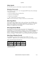
Video Inputs ........................................................................................................................ 3-15
Selecting Video Inputs ................................................................................................... 3-15
Selecting Filters................................................................................................................... 3-15
Selecting Sweep Modes ..................................................................................................... 3-15
Selecting a Display Format ................................................................................................. 3-15
AUDIO, VECTOR, and WAVEFORM ZOOM Buttons ........................................................ 3-16
Expanding the Audio Display ......................................................................................... 3-16
Expanding the Vector Display........................................................................................ 3-16
Expanding the Waveform Display.................................................................................. 3-16
Navigating the SETUP MENU ............................................................................................ 3-17
Calibration Pulse ................................................................................................................. 3-20
Calibration Interval .............................................................................................................. 3-20
STATUS, ERROR, and SC/H Indicators ....................................................................... 3-20
User-Interface Controls ....................................................................................................... 3-21
Front Panel Buttons / GPI/TALLY Connector / Keyboard.............................................. 3-21
Using the Keyboard Commands ......................................................................................... 3-23
VTM-200 Installation and Operation Handbook
i
Contents
Section 4 ♦ Troubleshooting
Cold Starting the VTM-200 ................................................................................................... 4-1
Problems, Causes, and Solutions......................................................................................... 4-2
Appendix A ♦ Specifications
General ................................................................................................................................. A-1
Inputs .................................................................................................................................... A-2
Outputs.................................................................................................................................. A-3
Interface ................................................................................................................................ A-4
Power Requirements ............................................................................................................ A-4
Environmental ....................................................................................................................... A-5
Mechanical ............................................................................................................................ A-5
Standard Accessories ...........................................................................................................A-5
Options.................................................................................................................................. A-5
Appendix B ♦ Service Support
Appendix C ♦ Pinouts
Appendix D ♦ Remote Control Unit (RCU-200)
Installing the RCU-200..........................................................................................................D-1
RCU-200 COM Port Electrical Interface Selection ..........................................................D-2
Interface Mode Jumper Configurations .......................................................................D-2
Operating the RCU-200 ........................................................................................................D-3
Troubleshooting ....................................................................................................................D-3
Specifications ........................................................................................................................D-3
Interface ...........................................................................................................................D-3
Power Requirements .......................................................................................................D-3
Environmental ..................................................................................................................D-4
Mechanical.......................................................................................................................D-4
Standard Accessories ......................................................................................................D-4
Options.............................................................................................................................D-4
Pinouts ..................................................................................................................................D-5
To Main Unit.....................................................................................................................D-5
5 VDC IN ..........................................................................................................................D-5
Appendix E ♦ Glossary
Index
ii
VTM-200 Installation and Operation Handbook
Contents
Figures
Figure 1-1. VTM-200 Front and Back Panels ........................................................................... 1-2
Figure 2-1. Mounting the VTM-200 in Rack.............................................................................. 2-3
Figure 2-2. VTM-200 Back Panel Connectors.......................................................................... 2-4
Figure 2-3. Connecting the RCU-200 Remote Control Panel .................................................. 2-6
Figure 3-1. VTM-200 Front Panel Controls and Indicators....................................................... 3-1
Figure 3-2. Sample SVGA display............................................................................................ 3-6
Figure 3-3. Full-Screen Waveform Graticule ............................................................................ 3-7
Figure 3-4. Unzoomed Full-Screen Vector Display .................................................................. 3-7
Figure 3-5. Unzoomed Full-Screen Audio Display ................................................................... 3-8
Figure 3-6. Four-Quadrant Display without a Video Signal (Non-Audio Menu) ....................... 3-8
Figure 3-7. Four-Quadrant Display without a Video Signal (Audio Menu) ............................... 3-9
Figure 3-8. Four-Quadrant Display with Upper Left Vector ...................................................... 3-9
Figure 3-9. Four-Quadrant Display with Lower Right Vector.................................................. 3-10
Figure 3-10. Unzoomed Display with Center Vector .............................................................. 3-10
Figure 3-11. 525/60 Serial Digital Input Full-Screen Waveform Graticule ............................. 3-11
Figure 3-12. NTSC Vector Graticule....................................................................................... 3-12
Figure 3-13. PAL Vector Graticule.......................................................................................... 3-12
Figure C-1. VGA OUT 15-pin Female Connector.....................................................................C-1
Figure C-2. RS-232/RS-422 COMM 9-pin Female Connector .................................................C-2
Figure C-3. GPI/TALLY (CONTROL) 9-pin Male Connector....................................................C-2
Figure C-4. Keyboard 9 Pin Female Connector .......................................................................C-3
Figure C-5. Audio IN A and B Connector .................................................................................C-4
Figure C-6. Audio OUT Connector ...........................................................................................C-4
Figure D-1. RCU-200 Back Panel Connectors .........................................................................D-1
Figure D-2. RCU-200 TO MAIN UNIT 9-pin Male Connector...................................................D-5
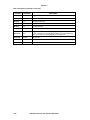
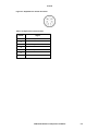
Tables
Table 2-1. Jumper Configuration for RS-422 Interface ............................................................ 2-2
Table 2-2. Parts Required to Rackmount the VTM-200 ........................................................... 2-3
Table 2-3. Description of Back Panel Connectors.................................................................... 2-4
Table 3-1. Description of Front Panel Controls and Indicators................................................. 3-1
Table 3-2. Video Formats and Units of Measure...................................................................... 3-6
Table 3-3. Default Settings ..................................................................................................... 3-14
Table 3-4. Input and Display Format Relationship ................................................................. 3-15
Table 3-5. SETUP Menu......................................................................................................... 3-18
Table 3-6. Status Indicators.................................................................................................... 3-21
VTM-200 Installation and Operation Handbook
iii
Contents
Table 3-7. Error Indicators (only visible for serial digital inputs)............................................. 3-21
Table 3-8. Keyboard Commands............................................................................................ 3-23
Table 4-1. VTM-200: Problems, Causes, and Solutions .......................................................... 4-2
Table C-1. VGA OUT Connector Pinouts.................................................................................C-1
Table C-2. RS-232 COMM Connector Pinouts ........................................................................C-2
Table C-3. GPI/TALLY (CONTROL) Connector Pinouts..........................................................C-2
Table C-4. Keyboard Connector Pinouts..................................................................................C-3
Table C-5. Audio Outputs and AES/EBU Audio Scales ...........................................................C-4
Table D-1. Description of RCU-200 Back Panel Connectors...................................................D-1
Table D-2. Jumper Configuration for RS-422 Interface (RCU-200) .........................................D-3
Table D-3. RCU-200: Problems, Causes, and Solutions .........................................................D-3
Table D-4. Pinouts for RCU-200 TO MAIN UNIT Connector ...................................................D-5
iv
VTM-200 Installation and Operation Handbook
Section 1 ♦ Introduction
The VTM-2001 is a 19” rackmounted unit that accepts two NTSC or PAL composite
video signals, two component serial digital inputs (per ITU-R BT.601 and SMPTE 259M
@ 270 Mb/s) at either 50 Hz or 59.94 Hz field rates, and an external analog reference
video signal. In addition, the VTM-200 optionally accepts four analog audio stereo
pairs, and four AES/EBU standard serial digital stereo pairs. The VTM-200 allows for
user selection of one of the video signals, plus two of the stereo pairs, and creates RGB
and sync signals suitable for driving a computer SVGA monitor at 800 x 600 pixel
resolution. The display presents the image carried by the selected video input as a
real-time, full motion picture; the waveform and vector representations of that input; and
the audio levels of the selected audio inputs, including phase differences between the left
and right channels of each of the stereo pairs. Front panel user controls allow for various
display and selection modes. An on-screen menu allows the user to set up default
conditions. Additional control can be exercised through the use of a computer keyboard
interface, and a GPI/TALLY connector.
Features include:
•
Two Analog Composite and two 601 Serial Digital inputs
•
Replaces two waveform monitor/vectorscopes, an audio test set, and two video
monitors
•
Dedicated buttons for all common functions
•
Versatile user configuration
•
SVGA display output
•
Zoom view on waveform Black (0 Units) and White (100 Units)
•
Zoom view on vectors each quadrant plus a center zoom for checking each color
and black/white balance
•
Zoom view on audio to set 0 dB reference
•
One rack unit high
•
Universal switching power supply: 90 to 260 VAC, 50 or 60 Hz
Options include:
•
One composite video output for NTSC and PAL monitors
•
OPT-1: Audio processing board
•
VTM-180 & VTM-200 Service and Instruction Manual
The VTM-200 is the perfect solution for unattended signal quality monitoring of
multiple sites.
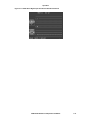
The front and back panels of the VTM-200 are illustrated in Figure 1-1.
1
This instrument is protected by US Patent 6,069,607. Other US and foreign patents pending.
VTM-200 Installation and Operation Handbook
1-1
Introduction
Figure 1-1. VTM-200 Front and Back Panels
For information on the RCU-200, see Appendix D, “Remote Control Unit (RCU-200).”
1-2
VTM-200 Installation and Operation Handbook
Section 2 ♦ Installation
This section provides information about inspecting the VTM-200 shipment and
installing the unit.
Inspecting the Shipment
Before installing the VTM-200, inspect the box and its contents. Report any damage to
the shipper and telephone Videotek’s Customer Service Department for service support
(see Appendix B, “Service Support”).
The box contains the following:
•
The VTM-200
•
One VTM-200 Installation and Operation Handbook
•
One 75Ω high-frequency terminator
•
One power cord
•
Hardware kit, Item Number 045592, for rackmounting the VTM-200
Save the box and packing material for any future shipping requirements.
Installing the VTM-200
The following subsections provide instructions to rackmount, connect, and configure
the unit.
VTM-200 Installation and Operation Handbook
2-1
Installation
COM Port Electrical Interface Selection
CAUTION — these instructions are for use by qualified personnel only. To reduce
the risk of electric shock, do not perform this installation or any servicing unless you
are qualified to do so. Refer all servicing to qualified service personnel.
The COM interface on the VTM-200 as well as the Remote Control Unit (RCU-200)
normally uses an EIA-232 electrical interface for communications. Both the RCU and
the VTM units are capable of utilizing an alternate cable interface, RS-422, which
permits longer inter-unit cabling distances. In order to support an RS-422 connection
the internal jumpers must be reconfigured. See Interface Mode Jumper Configurations
for more details.
Interface Mode Jumper Configurations
In order to utilize the RS-422 interface, internal jumpers in both the VTM and RCU
units must be repositioned. Table 2-1 details the jumper configuration for the
VTM-200 (for more information on the RCU-200, See Appendix D, “Remote Control
Unit (RCU-200)”). All signal and power cabling should be removed from the units
before disassembly.
The jumpers on the VTM-200 are located near the back connector area of the VTM204
board. In a VTM-200 with an audio option board installed, the jumpers would be
located under the audio option board, which must be temporarily removed in order to
reconfigure the jumpers.
Table 2-1. Jumper Configuration for RS-422 Interface
Connection
Jumper CN1
Jumper CN3
Jumper CN5
EIA-232
Connect 1-2
No connection
No connection
RS-422
No connection
Connect 1-2
Connect 1-2
2-2
VTM-200 Installation and Operation Handbook
Installation
Rackmounting the VTM-200
Rackmount the VTM-200 with the enclosed rackmounting support rails. The ideal
situation would leave one rack unit (1.75") above and below the VTM-200 open. When
selecting the permanent mounting location for the VTM-200, ensure that the flow of air
to the ventilation holes on the top and sides of the chassis is not obstructed.
Rackmounting of the VTM-200 is illustrated in Figure 2-1; the parts required to
rackmount the VTM-200 are listed in Table 2-2.
Figure 2-1. Mounting the VTM-200 in Rack
Table 2-2. Parts Required to Rackmount the VTM-200
Key
Item Number
Quantity
Description
1
044030
8
Hardware screw #10-32 x ¾ pan head.
2
045020
4
Hardware nylon washer
3
200076
2
Metal rack extension bracket
Rack-extension mounting brackets are mounted to the back of the rack cabinet. Once
in place, guides on the unit will slide in and out of rack extensions for easy installation
and removal.
VTM-200 Installation and Operation Handbook
2-3
Installation
Connecting the VTM-200
The back panel connectors are illustrated in Figure 2-2; the function of each connector
is described in Table 2-3.
Figure 2-2. VTM-200 Back Panel Connectors
Table 2-3. Description of Back Panel Connectors
Key
Label
Description
REFERENCE
BNC connector that connects to an external NTSC/PAL reference signal
(video or blackburst) from which the horizontal and vertical sync, and the
color burst frequency for the VTM-200 will be derived if EXT has been
selected as the REF source. If these connectors are not looped through,
then the unused connector must be terminated in 75Ω.
3
A (ANALOG VIDEO
INPUT)
BNC that connects to an NTSC or PAL analog composite signal in the
amplitude range of 0.5 to 2V p-p with a maximum of ± 3.0 volts of offset on
it.
4
B (ANALOG VIDEO
INPUT)
BNC that connects to an NTSC or PAL analog composite signal in the
amplitude range of 0.5 to 2V p-p with a maximum of ± 3.0 volts of offset on
it.
5
C (DIGITAL VIDEO
INPUT)
BNC that connects to a serial digital stream at 270 MHz per recommendation ITU-R BT.601 and SMPTE 259M standard. Either 525 line at 60 Hz
field rate or 625 line at 50 Hz field rate signals are accepted.
6
D (DIGITAL VIDEO
INPUT)
BNC that accepts a serial digital stream at 270 MHz per recommendation
ITU-R BT.601 and SMPTE 259M standard. Either 525 line at 60 Hz field
rate or 625 line at 50 Hz field rate signals are accepted.
7
HOLE PLUGS
Reserved for future functionality.
8
COMPOSITE VIDEO
OUTPUT JACK
Option. NTSC or PAL depending on video output format.
1
2
(Table continues on next page)
2-4
VTM-200 Installation and Operation Handbook
Installation
Table 2-3. Description of Back Panel Connectors (continued)
Key
Label
Description
VGA (OUTPUTS)
Female, 15-pin, “D” connector that provides the analog RGB signals and the
vertical and horizontal sync signals necessary to operate a standard SVGA
monitor at 800 x 600 resolution.*
COM (CONTROL)
Female, 9-pin, “D” connector that allows RS-232/RS-422 communication
with the RCU-200 or the PC. The communication parameters are no parity,
8 data bits, and baud rate selectable from the SETUP menu (as shown in
Table 3-5 on page 3-18).*
GPI/TALLY (CONTROL)
Male, 9-pin, “D” connector for remote selection of the video input by
accepting momentary contact closures to the Channel Select Return line. It
also accepts a continuous contact closure to the ON AIR Return line to
indicate ON AIR status by causing the on-screen ON AIR indicator area to
turn red. The Error Summary signal, the only output of this connector, is the
normally open contact of a relay that makes contact with Error Summary
Return for approximately one second, if the selected input is from a serial
digital source, and an EDH or Data Error occurs.*
KEYBOARD
6-pin, mini, DIN connector for an IBM PS2-style keyboard connector to allow
user remote control of the VTM-200.*
AES/EBU IN C1
BNC connector for an AES/EBU serial digital stream carrying a stereo pair of
audio channels. The 18 most significant bits of each channel are converted
to analog form. If selected for display and output via the AUDIO FOLLOW
Menu Items, the analog audio derived from the selected AES/EBU input will
appear at the AUDIO OUT connector with an attenuation determined by the
AES/EBU AUDIO LEVEL Menu Item. Its levels and phase difference will be
displayed in the on-screen audio display.
14
AES/EBU IN C2
Same as 13.
15
AES/EBU IN D1
Same as 13.
16
AES/EBU IN D2
Same as 13.
AUDIO IN A1, A2
Twenty screw-terminal connectors for eight analog audio signals (four stereo
pairs). Each signal input accepts a balanced input (H, L) and a shielded
ground (G). If selected for display and output via the AUDIO FOLLOW
Menu Items, the analog audio will appear at the AUDIO OUT connector with
an attenuation determined by the ANALOG AUDIO LEVEL Menu Item. Its
levels and phase difference will be displayed in the on-screen audio display.
AUDIO IN B1, B2
Same as 17.
AUDIO OUT 1, AUDIO
OUT 2
Ten screw-terminal connectors that output the two analog audio stereo pairs
selected by the AUDIO FOLLOW Menu Items. The gain of the audio is
determined by the AES/EBU AUDIO LEVEL and ANALOG AUDIO LEVEL
Menu Items. Its levels and phase difference will be displayed in the on-screen
audio display.*
INPUT POWER
Three-prong power connector that accepts nominal 115V AC to 230V AC, 50
to 60 Hz single phase to power the VTM-200. The VTM-200 will auto detect
the supply voltage, and adjust itself to it. The connector incorporates an
inline 5 x 20 mm 2.0 A time-lag fuse.
FAN
Seven-cfm fan operates whenever power is applied to the VTM-200, and
functions to cool the VTM-200. It exhausts air out of the unit.
9
10
11
12
13
17
18
19
20
21
*See Appendix C, “Pinouts,” for the connections.
VTM-200 Installation and Operation Handbook
2-5
Installation
Configuring the VTM-200 for Remote Control
For the following configuration, the interconnecting cables can be extended using
electronic distribution. To configure the VTM-200 for remote control:
♣• One RCU-200 connected to one VTM-200 using the COM port
Figure 2-3. Connecting the RCU-200 Remote Control Panel
2-6
VTM-200 Installation and Operation Handbook
Section 3 ♦ Operation
The VTM-200 provides a rasterized output picture/waveform/vector/audio display on
an SVGA monitor with an on-screen menu system for operator setup of the unit. The
front panel controls allow for selection of inputs, filters, display parameters, and
display formats.
Front Panel Controls and Indicators
The front panel controls and indicators are illustrated in Figure 3-1; the function of
each control or indicator is described in Table 3-1.
Figure 3-1. VTM-200 Front Panel Controls and Indicators
Table 3-1. Description of Front Panel Controls and Indicators
Key
1
Label
Description
POWER
LED lights to indicate that power is applied to the VTM-200.
DISPLAY
Press to cycle through the SVGA display from a four-quadrant display to a full
screen display of the picture being processed, a full screen waveform display,
a full screen vector display, a full screen audio levels display if the OPT-1
option is installed, and then the four-quadrant display once more.
REF
Press to select either the externally applied signal at the REFERENCE input
or the signal being processed to function as the source for horizontal and
vertical sync and color reference.
INT, EXT
LED lights to indicate that the source of reference is either internal or
external.
INPUT
Press to select signal A, B, C, or D for subsequent processing and display.
A, B, C, and D
LED lights to indicate which signal is being processed and displayed. The
signal can be selected by the front panel INPUT button, by contact closures
at the TALLY connector or by a keyboard connected to the keyboard
connector.
FILTER
Press to select an NTSC/PAL signal that undergoes no filtering (FLAT), LOW
PASS filtering, or CHROMA filtering.
FLAT, LOW PASS,
CHROMA
LED lights to indicate the filter that has been selected.
2
3
4
5
6
7
8
(Table continues on next page)
VTM-200 Installation and Operation Handbook
3-1
Operation
Table 3-1. Description of Front Panel Controls and Indicators (continued)
Key
Label
Description
SWEEP
Press to cycle the waveform between 1H (one horizontal line of video), 2H
(two successive lines of video), 1V (one vertical field of video), or 2V (two
successive fields of video).
1H, 2H, 1V, 2V
LED lights to indicate which SWEEP is currently in operation.
H. MAG
Press to select, for the waveform display, either a normal horizontal sweep or
a sweep that has been horizontally magnified by a factor of 5.
x5
LED lights when the horizontal waveform sweep has been magnified by a
factor of 5.
V. GAIN
Press to select, for the waveform display, either a vertical gain of 1 or a
vertical gain of 2.5.
x2.5
LED lights when the vertical waveform gain has been increased by a factor of
2.5.
FORMAT
Press to select the format in which the waveform is displayed. Component
video at the C or D video inputs can be displayed as either RGB components
(which may be paraded or overlaid) Y, CB, CR components (which may be
paraded or overlaid), or as an equivalent COMPOSITE waveform which has
been synthesized internal to the VTM-200. The waveforms of NTSC/PAL
signals at the A or B video inputs can only be displayed in COMPOSITE
format. The vectors display for component video inputs displays Cb vs. Cr.
The vector display for composite video inputs displays B-Y vs. R-Y.
RGB, YCBCR,
COMPOSITE
LED lights to indicate which display FORMAT has been selected.
AUDIO (ZOOM)
This button has a dual purpose:
9
10
11
12
13
14
15
16
Press to select, for the audio levels display, either the SETUP preselected scales calibrated in dB or scales that have been zoomed in the
region of 0 dB to display more detail.
17
When the SETUP menu is displayed, this button functions to select only
those items concerned with audio, and forces the menu to appear in the
screen quadrant normally occupied by the vector display. This button is
active only when the OPT-1 option is installed.
18
ON (AUDIO ZOOM)
LED lights when the audio scales have been zoomed to present a more
detailed display.
VECTOR (ZOOM)
Press to cycle through the vector display through different views. These
include normal display, center zoomed display, and one vector quadrant
zoomed display, as follows:
ON (VECTOR ZOOM)
LED lights when a vector display other than the normal display is shown.
19
20
(Table continues on next page)
3-2
VTM-200 Installation and Operation Handbook
Operation
Table 3-1. Description of Front Panel Controls and Indicators (continued)
Key
21
Label
Description
WAVEFORM (ZOOM)
This button has a dual purpose:
Press to cycle through the composite waveform display between its
normal display of -50 to 120 IRE levels, a display zoomed around a
center value of 0 IRE ± 20 IRE, and a display zoomed around a center
value of 100 IRE ± 20 IRE. The PAL waveform, when displayed as volts,
cycles between -0.1 to +0.7 volts, 0 ± 0.1 volts, and + 0.7 ± 0.1 volts.
This button has a dual use.
When the SETUP menu is displayed, this button functions to select only
those items not concerned with audio, and forces the menu to appear in
the screen quadrant normally occupied by the audio levels display.
22
ON (WAVEFORM
ZOOM)
LED lights when the waveform display is zoomed around either 0 IRE or 100
IRE in composite mode; +0.0 or +0.7 volts in component mode.
23
SETUP
Press to enter or exit the SETUP menu.
24
LINE SELECT
Press to enter or leave the line select mode. In this mode, the waveform and
vector displays show only one line out of an entire two-field frame of video.
When not in the line select mode, the displays accumulate all of the video
lines, with those occurring earlier in time decaying in brightness, simulating
the persistence of the phosphor in an ordinary oscilloscope CRT.
25
ON (LINE SELECT)
LED lights when in the line select mode, displaying only one line.
26
LINE
Rotate to select which line the waveform and vector displays when line select
mode is operative. The line number and field identification are displayed at the
bottom of the waveform display. For an NTSC or 525/60 signal, 1 odd to 263
odd, 1 even to 262 even are shown. For a PAL or 625/50 signal, line number
ranges from 1 to 625, with lines 1 through 313 being designated in the odd
field, and lines 314 through 625 being in the even field. Clockwise rotation of
the LINE control increases the selected line number; counterclockwise rotation
decreases it. For component displays, each component is individually shown
before the line number is incremented or decremented.
27
H (WAVEFORM
POSITION)
This control has a dual purpose:
Rotate to control the horizontal waveform position.
If the SETUP menu is visible, this control allows the user to select menu
items.
28
V (WAVEFORM
POSITION)
This control has a dual purpose:
Rotate to control the vertical waveform position.
If the SETUP menu is visible, this control allows the user to select the
values of the displayed menu item.
29
VECTOR PHASE
Rotate to control the rotation of the composite vector display through 360°.
This allows positioning of the tips of the display within the graticule targets
that represent the correct phases for color bar test patterns.
VTM-200 Installation and Operation Handbook
3-3
Operation
Making Digital Video Measurements with the VTM-200
The VTM-200 monitors analog NTSC/PAL composite and serial component digital
video.
Video adhering to the ITU-R BT.601/SMPTE 259 standards consists of three
component channels multiplexed into a single data stream. The three components are
luminance (or "Y") and two color difference signals (CB and CR). The color difference
signals are similar to the more familiar analog color difference components B-Y and
R-Y. The significant difference is in amplitude scaling, which leads to an important
point to remember when measuring serial component digital signals: All three
components of a 100% signal will have the same maximum peak to peak
amplitude. The VTM-200 graticule shows this maximum legal excursion as 0 volt to
+0.7 volt. For example, a 100% color bar signal with a white flag will have all three
components (Y, CB, and CR), ranging from 0V to +0.7 V. Y channel blanking level is
0 volt, and both CB and CR blanking levels are 0.35 volt. If a 75% signal with a 100%
white bar is viewed on the VTM-200, the Y channel will still range from 0 to +0.7 volt,
since the 75% refers to color saturation. In this case, peak-to-peak excursion for the CB
and CR channels will now be 75% of 0.7 volt, or 0.525 volt peak-to-peak. This range is
centered on blanking level (0.35 volt), so the maximum excursion of CB and CR with
75% saturation is 0.0875 volt to 0.6125 volt. These are the only peak-to-peak
excursions for the color difference channels; there are not the range of standards with
serial component digital video that there are with analog component (Beta, MII, EBU,
SMPTE, etc.). Amplitudes are the same in both 50 Hz and 60 Hz serial component
digital video.
Another difference between viewing analog and digital component video is the
blanking portion of the signals. Unlike analog, a digital component has no sync pulse
or other synchronizing portion of the signal. There are synchronizing data words at the
beginning and end of blanking, but these do not look like sync pulses. Only the active
video portion of the signal is displayed on the VTM-200, but this is precisely
controlled so that timing measurements can be made relative to the first displayed
pixel. The first displayed pixel is the first active video sample after SAV (Start of
Active Video - the synchronizing words that appear at the end of blanking). A SETUP
menu item allows for the display or blanking of spikes representing the SAV and EAV
(End of Active Video) that indicate the beginning and end of each component.
The graticule scales change when displaying waveforms as RGB or composite signals.
The RGB display is useful for gamut checking—any portion of the signal that
extends more negative that 0 volts or more positive than +0.7 volts in a RGB
display is invalid and the cause of a GAMUT error. Displaying an input as a
composite signal is a quick check of its suitability for encoding. Still, 100% saturated
signals will not encode properly. A quick check when displaying a composite waveform is to examine whether the chrominance extends above or below the luminance
limits. Remember, the peak luminance for 60 Hz signals is 0.714 volt, slightly
above the 0.7 volt graticule line.
3-4
VTM-200 Installation and Operation Handbook
Operation
GENERAL CHARACTERISTICS OF SERIAL COMPONENT
SIGNALS
•
Serial data rate: 270 Mb/s
•
Serial digital signal amplitude: 800 mV p-p (Note: not video signal amplitudes)
•
1440 data words in active video
•
276 data words in horizontal blanking (525 line system)
•
288 data words in horizontal blanking (625 line system)
•
Serial transmission uses 10-bit words but 8-bit words are allowed (lower two bits
set to logical 0)
SUPER VGA (SVGA) Display
Figure 3-2 illustrates a four-quadrant display of a serial digital signal. The picture in
the upper right quadrant indicates that the signal is a full field color bar test pattern.
The waveform display in the lower right quadrant has been set to display the Y, CB,
and CR components of the signal in a time-paraded fashion. Above the waveform, the
vertical gain is indicated as being x1, and the horizontal waveform time scale is
indicated as 15 μs per major division. In the lower left quadrant, the vector display
shows the color content of the signal as a plot of CB horizontally versus CR vertically.
The tie lines between targets within the circle indicate the transitions between colors in
the test pattern. The STATUS is indicated between the waveform and vector displays.
The signal is not ON AIR, because the ON AIR legend background is not illuminated
in red. The SOURCE ID has been set to read INPUT C. The ERROR conditions
shown are: no GAMUT error, EDH present, but no EDH errors are occurring; and no
DATA errors are occurring. At the lower left of the vector display, the signal standard
is indicated as 525 (lines per frame) / 60 (Hz vertical rate), the selected INPUT is again
identified as being on connector C, and the selected REFRENCE (REF) is indicated as
INTERNAL (INT). The audio levels display in the upper left quadrant.
The source of the audio is indicated as channel C, which is a serial digital source, with
the REF set for -20 dBfs. This means that a digital audio signal at a level 20 dB below
the analog level corresponding to the full scale value will be represented as a green bar
extending from the bottom of a scale to the zero mark on the scale. The LEFT (L)1,
RIGHT (R)1, L2, and R2 audio components of channel C are all at levels of 0 dB
relative to the reference. The φ1 phase difference scale shows its yellow indicator
mark as being in the upper red area between the 0 and -1 marks. This means that the
phase difference between L1 and R1 is more than 90° (0 mark) and is approaching
180° (-1 mark). The implication is that the audio signals on L1 and R1 are either 2
independent monophonic channels, or that the signal polarity of one of them is
reversed, if they really are a stereo pair. The φ2 phase difference scale shows the
signals on L2 and R2 at a less than 90° phase difference.
VTM-200 Installation and Operation Handbook
3-5
Operation
Figure 3-2. Sample SVGA display
Waveform, Vector, and Audio Graticule Scales
Waveform Graticule Scales
The waveform graticule scales change according to the video format being displayed,
as listed in Table 3-2.
Table 3-2. Video Formats and Units of Measure
Video Format
Unit of Measure
NTSC composite
IRE
PAL composite
Units or V (selectable)
Digital 525
V
Digital 625
V
Because of the large number of possible front panel control setting combinations, it is
impractical to show every possible screen display. However, the following examples
represent a cross section of what graticules and arrangements of displays can
reasonably be expected.
Figure 3-3 illustrates a full-screen waveform graticule with no signal displayed.
INPUT A has been selected, and the REF is internal. The signal standard is NTSC.
The STATUS is not ON AIR, and the SOURCE ID has been set to read INPUT A.
The SC/H phase is measured to be 0°. The vertical gain is x1, the horizontal time scale
is 5.0 μs per major division, and the FLAT (FL) filter has been selected. The -40 and
+100 IRE scale lines are indicated.
3-6
VTM-200 Installation and Operation Handbook
Operation
Figure 3-3. Full-Screen Waveform Graticule
Figure 3-4 shows an unzoomed, full-screen vector display graticule with no signal
displayed. INPUT A has been selected, and the REF is internal. The signal standard is
NTSC. The STATUS is not ON AIR, and the SOURCE ID has been set to read
INPUT A. The SC/H phase is measured to be 0°. Red, Magenta, Yellow, Blue,
Green, and Cyan are targets for a color bar test pattern and the horizontally indicated
area in which the back porch color burst should fall.
Figure 3-4. Unzoomed Full-Screen Vector Display
Figure 3-5 shows an unzoomed full-screen audio levels display with audio signals
present. Audio channel A has been selected, and the 0 marks on the vertical scales
correspond to the audio reference of +8 dBm. The STATUS is not ON AIR, and the
SOURCE ID has been set to read INPUT A. The SC/H phase is measured to be 0°.
The instantaneous level of audio source L1 is about 0 dB, and that of audio source R1
is +12 dB or more. L2 and R2 levels are about +8 and +1 dB. The phase differences
between L1 and R1, and L2 and R2 are each less than 90°.
VTM-200 Installation and Operation Handbook
3-7
Operation
Figure 3-5. Unzoomed Full-Screen Audio Display
Figure 3-6 illustrates a four-quadrant display with no video signal present, and the
(non-audio) SETUP menu displayed as a result of the front panel SETUP button having
been pressed. The menu item displayed is Waveform Color, and the currently selected
value for that item is Green. On-screen instructions indicate “Choose an item with
the H Pos knob. Change its value with the V Pos knob.” To select audio-related
setup menu items, “Press ‘Audio Zoom’ for audio setup.” To remove the SETUP
menu, “Press ‘Setup’ again to exit setup.
Figure 3-6. Four-Quadrant Display without a Video Signal (Non-Audio Menu)
3-8
VTM-200 Installation and Operation Handbook
Operation
Figure 3-7 illustrates a four-quadrant display with no video signal present, and the
(audio) SETUP menu displayed as a result of the front panel SETUP button having
been pressed, followed by a press of the AUDIO ZOOM button. The menu area
overwrites the vector display area. The selected menu item is Analog Audio Scale, and
the selected item value is Type I (+8 dBm). By moving the menu area over the vector,
the audio quadrant becomes visible so the effects of menu changes can be viewed
before the menu is exited.
Figure 3-7. Four-Quadrant Display without a Video Signal (Audio Menu)
Figure 3-8 shows a four-quadrant display with no video signal present, and with audio
present. The waveform graticule has been zoomed to the region around 0 IRE. The
7.5 IRE is a dotted graticule line that corresponds to picture black level. The vector
graticule has been zoomed to the top left quadrant. The audio scales remain unzoomed.
Audio channel A has been selected, and the 0 marks on the vertical scales correspond
to the audio reference of +8 dBm. The STATUS is not ON AIR, and the SOURCE ID
has been set to read INPUT A. The signal standard is NTSC. The SC/H phase is
measured to be 0°. The vertical gain is x1, the horizontal time scale is 5.0 μs per major
division, and the FLAT (FL) filter has been selected.
Figure 3-8. Four-Quadrant Display with Upper Left Vector
VTM-200 Installation and Operation Handbook
3-9
Operation
Figure 3-9 is similar to Figure 3-8, except that the waveform graticule has been
zoomed to the region around 100 IRE, and the vector display has been zoomed to its
lower right quadrant.
Figure 3-9. Four-Quadrant Display with Lower Right Vector
Figure 3-10 is similar to Figure 3-8 and Figure 3-9, except that the waveform
graticule is unzoomed, and the vector area has been zoomed to its center.
Figure 3-10. Unzoomed Display with Center Vector
Figure 3-11 shows a full-screen waveform graticule set for a 525/60 serial digital
input, but with no video signal shown. The gain is x1, and the horizontal scale is
15.0 μs per major division. The selected input is C, and the selected REF is internal.
The ON AIR status has been set to indicate that the signal is on the air, and the
SOURCE ID has been set for INPUT C, although any two lines of six characters could
have been displayed. There are no GAMUT errors, EDH is present in the serial digital
stream, and there are no DATA errors. The waveform graticule is calibrated in volts,
with dotted lines corresponding to salient points in a component test waveform.
3-10
VTM-200 Installation and Operation Handbook
Operation
Figure 3-11. 525/60 Serial Digital Input Full-Screen Waveform Graticule
VTM-200 Installation and Operation Handbook
3-11
Operation
Vector Graticule Scales
The vector graticule scales also change according to the video format being displayed;
these scales are illustrated in Figure 3-12 and Figure 3-13.
Figure 3-12. NTSC Vector Graticule
Figure 3-13. PAL Vector Graticule
3-12
VTM-200 Installation and Operation Handbook
Operation
Audio Ballistics
The audio display is an option. The audio levels are represented by bar graph level
meters with characteristics selectable to be either IEC Type I, IEC Type IIa, IEC Type
IIb, Type I +8, or Nordic for both analog and digital inputs; for digital inputs only, the
dBfs scale is selectable. The IEC types are according to IEC-268-10 and -17
specifications. The graticules are calibrated in dB, and the selected reference level,
(either 0, +4, +6, +8, or +12 dBm for analog audio inputs, or -22, -20, or -18 dBfs for
digital audio inputs) corresponding to the 0 mark is listed, along with the audio source.
In addition to the L1, R1, L2, and R2 level scales, there are φ1 and φ2 phase
difference scales. φ1 measures the instantaneous phase difference between the
signals applied to the L1 and R1 scales. φ2 measures the instantaneous phase
difference between the signals applied to the L2 and R2 scales. The φ scales are
calibrated in +1 (0°), 0 (90°), and -1 (180°) markings. The region between +1 and 0 is
green; the region between 0 and -1 is red; a yellow indicator mark shows the phase
difference.
The audio scales and ballistics both attack and delay times for meter movement. The
following meter responses can be selected:
•
NORMAL
•
PEAK
•
PEAK HOLD
VTM-200 Installation and Operation Handbook
3-13
Operation
Factory-Default Settings
When the VTM-200 is powered on for the first time, it assumes the factory-default
settings. These default settings are listed in Table 3-3.
Table 3-3. Default Settings
Key
Menu Item
Default Value
1
Waveform Color
Lt. Green
2
Vector Color
Yellow
3
Background Color
Black
4
Graticule Color
White
5
Waveform Intensity
0
6
Vector Intensity
0
7
SAV/EAV Blanking
On
8
DC Restore
On
9
Persistence
Normal
10
Waveform Overlay
Parade
11
PAL Vector
Normal
12
Vector Horz Center
0
13
Vector Vert Center
0
14
Picture Enable
On
15
Picture Brightness
0
16
Picture Contrast
0
17
Picture Saturation
0
18
Picture Hue
0
19
Analog Vector
75%
20
CCIR-601 Vector
100%
21
Video Standard
Auto Detect
22
Baud Rate
38400
23
Cal
Off
24
Screen Saver
Off
25
PAL Waveform
Units
26
Audio Follow Input A
Audio Input A
27
Audio Follow Input B
Audio Input B
28
Audio Follow Input C
Audio Input C
29
Audio Follow Input D
Audio Input D
30
Audio Response
Normal (IEC 268-
31
Analog Audio Scale
Type I (+4 dBm)
32
AES/EBU Audio Scale
Type I (-20 dBfs)
33
Sum/Difference
L1 / R1 / L2 / R2
3-14
VTM-200 Installation and Operation Handbook
Operation
Video Inputs
The VTM-200 accepts two video formats: composite and serial digital.
Selecting Video Inputs
Press INPUT next to the A, B, C, or D. Pressing the INPUT button will cycle through
a four-quadrant display:
•
Full-screen display of the processing picture
•
Full-screen waveform display
•
Full-screen vector display
•
(OPT-1 Option) Full-screen audio level display
NOTE: The video is in Parade mode. To change to Overlay mode, use the SETUP MENU.
Selecting Filters
There are three filters available: Flat, Low Pass, and Chroma. Press FILTER to select
the next filter. Multiple filters can function simultaneously. Only the FLAT selection
applies to the components of signals applied at the C or D video connectors. No
filtering is ever applied to the vector display.
Selecting Sweep Modes
Press SWEEP to select one of the four sweep modes: 1H (1 Horizontal), 2H
(2 Horizontal), 1V (1 Vertical), and 2V (2 Vertical). 1H or 1V SWEEP is possible when
paraded components have been selected for display, the only a 1H or 1V SWEEP is
possible. Overlaid components are shown in a 1H display, and paraded components are
shown in a 3H display. If LINE SELECT is set to ON, then only 1H sweep is possible.
Selecting a Display Format
Press FORMAT to select one of three display formats: RGB, YCBCR, and
COMPOSITE. Table 3-4 lists the relationships between the input and display formats:
Table 3-4. Input and Display Format Relationship
Input/Format
RGB
YCBCR
Composite
Composite
No
No
Yes
Digital
Yes
Yes
Yes
1 Not available for RGB formats.
2 Available with YC input only.
VTM-200 Installation and Operation Handbook
3-15
Operation
AUDIO, VECTOR, and WAVEFORM ZOOM Buttons
There are three ZOOM buttons: WAVEFORM, VECTOR, and AUDIO. The following
subsections explain their use.
Expanding the Audio Display
NOTE: This button is only active when the OPT-1 option is installed.
Press AUDIO ZOOM to select one of the display options:
•
Expand the audio scales around the 0 dB reference point and enable increased
resolution of readings.
•
Select items in the SETUP menu that are only concerned with audio.
•
Forces the SETUP menu to appear in the screen quadrant normally occupied by the
vector display.
Expanding the Vector Display
Press VECTOR ZOOM to select one of five expanded display options:
•
Expand the center
•
Expand the upper-left quadrant
•
Expand the upper-right quadrant
•
Expand the lower-right quadrant
•
Expand the lower-left quadrant
As with AUDIO ZOOM, the VECTOR ZOOM is helpful when increased resolution of
phase or saturation readings is required.
Expanding the Waveform Display
Press WAVEFORM ZOOM to select one of three display options:
•
NORMAL or no expansion display of –50 to +120 IRE
•
ZOOM positioned with a center value of 0 IRE and going to +20 IRE
•
ZOOM positioned on the 100 IRE and reaching to +120 IRE
At each zoom position, the graticule scale and waveform displays expand to provide
more resolution around the zoom point.
3-16
VTM-200 Installation and Operation Handbook
Operation
Navigating the SETUP MENU
Press SETUP/LEARN to display or exit the SETUP MENU. Use the following knobs
to navigate and select values on the SETUP MENU:
•
WAVEFORM POSITION-H
− Rotate the knob left or right to move the menu cursor or to change a value or
condition in a menu.
− Stop knob at desired item.
•
WAVEFORM POSITION-V
− Rotate the knob to change a selected value or move a graticule cursor line.
− Stop knob at the desired value.
Enter the Setup mode to display the SETUP MENU.
VTM-200 Installation and Operation Handbook
3-17
Operation
Table 3-5. SETUP Menu
Menu Item
Item Values
WAVEFORM COLOR
*16 colors
VECTOR COLOR
*16 colors
BACKGROUND COLOR
*16 colors
GRATICULE COLOR
*15 colors
WAVEFORM INTENSITY
-32 to +32
VECTOR INTENSITY
-32 to +32
SAV/EAV BLANKING
On
Off
DC RESTORE
On
Off
PERSISTENCE
Normal
Infinite
WAVEFORM OVERLAY
Overlay
Parade
PAL VECTOR
Normal
Overlay
VECTOR HORZ CENTER
-128 to +127
VECTOR VERT CENTER
-128 to +127
On
PICTURE ENABLE
Off
PICTURE BRIGHTNESS
-128 to +127
PICTURE CONTRAST
-128 to +127
PICTURE SATURATION
-128 to +127
PICTURE HUE
-128 to +127
ANALOG VECTOR
75%
100%
CCIR-601 VECTOR
75%
100%
Auto Detect
VIDEO STANDARD
300
BAUD RATE
NTSC (525/60)
1200
2400
4800
PAL (625/50)
9600
19,200
On
CAL
38,400
Off
Off or 1–120 minutes
SCREEN SAVER
Units
PAL WAVEFORM
Volts
AUDIO FOLLOW INPUT A
CH. A
CH. B
CH. C
CH. D
AUDIO FOLLOW INPUT B
CH. A
CH. B
CH. C
CH. D
AUDIO FOLLOW INPUT C
CH. A
CH. B
CH. C
AUDIO FOLLOW INPUT D
CH. A
CH. B
CH. C
AUDIO RESPONSE
ANALOG AUDIO SCALE
Normal
CH. D
** GR.
1
CH. D
** GR.
1
Peak
** GR. ** GR.
3
4
** GR. ** GR.
3
4
Peak Hold
Type I
Type IIa
Type IIb
(0, 4, 6, 8, or 12 dBm)
(0, 4, 6, 8, or 12 dBm)
(0, 4, 6, 8, or 12 dBm)
Type I +8
Nordic
(0, 4, 6, 8, or 12 dBm)
(0, 4, 6, 8, or 12 dBm)
*Colors listed in the Display Colors Menu.
(Table continues on next page)
** Selection available only with OPT-2 installed.
3-18
** GR.
2
** GR.
2
VTM-200 Installation and Operation Handbook
Operation
Table 3-5 SETUP Menu (continued)
Menu Item
AES/EBU AUDIO SCALE
SUM/DIFFERENCE
Item Values
Type I
(-18, -20, or –22 dBfs)
Type I +8
(-18, -20, or -22 dBfs)
L1/R1/L2/R2
Type IIa
(-18, -20, or -22 dBfs)
Nordic
(-18, -20, or -22 dBfs)
L1/R1/M1/S1
Type Iib
(-18, -20, or -22 dBfs)
dBfs
(-9, -18, -20, or -22
dBfs)
L2/R2/M2/S2
M1/S1/M2/S2
Display Colors Menu
Black
Blue
Green
Cyan
Red
Purple
Brown
LT Gray
DK Gray
LT Blue
LT Green
LT Cyan
LT Red
LT Purple
Yellow
White
NOTE: LT=Light and DK=Dark
VTM-200 Installation and Operation Handbook
3-19
Operation
Calibration Pulse
Checking on the accuracy of the waveform graticule and the vertical gain of the
VTM-200 circuits that process composite waveforms, a calibration pulse is selected for
display in lieu of the normal composite waveform. The SETUP menu item CAL has as
the values ON and OFF. If CAL pulse is selected, a squarewave several cycles in
duration will be displayed. The squarewave amplitude corresponds to 140 IRE in
NTSC and 143 UNITS in PAL and is processed by the same circuits that normally
process the composite waveform. By adjusting the squarewave position vertically with
the front panel WAVEFORM POSITION-V knob, it should be possible to place the
top and bottom of the squarewave directly on the -40 and +100 lines in NTSC and -43,
+100 lines in PAL of the unzoomed waveform graticule, in order to verify calibration.
Calibration Interval
Calibration is recommended under any of the following conditions:
•
Every 12 months
•
When critical components are replaced
•
After exposure to temperatures outside of the specified operating or storage
temperatures
NOTE: If calibration is needed, refer to Appendix B for service and support.
STATUS, ERROR, and SC/H Indicators
Between the waveform and vector displays, and on full screen waveform and vector
displays, the VTM-200 shows STATUS information, and for serial digital inputs only,
ERRORS information. The background color that surrounds the indicating text
provides the user with useful information, summarized in the tables that follow.
Definitions of the listed errors:
•
GAMUT ERROR - When the transcoded RGB representation of a digital input
extends above 0.7V or below 0V during the active picture portion of the video.
•
DATA ERROR - When the presence of a signal is detected on a digital input but
TRS (Timing Reference Sequence) cannot be detected.
•
EDH ERROR - When the presence of the EDH header is detected and either the
active picture or full field CRCs (Cyclic Redundancy Checks) calculated by the
VTM-200 do not match the CRC values embedded in the selected digital video
signal.
•
EDH PRESENT - When there is no EDH ERROR and the VTM-200 has detected
the presence of the EDH header on the selected digital video input.
3-20
VTM-200 Installation and Operation Handbook
Operation
Table 3-6. Status Indicators
Indicator
Background color
ON AIR
clear – off the air
SOURCE ID
2 lines of text, 6 characters per line, entered from the keyboard at the user's option
red – on the air
Table 3-7. Error Indicators (only visible for serial digital inputs)
Indicator
Background color
GAMUT
clear – no errors
yellow – error(s)
EDH
clear – EDH not present
green – EDH present,
no errors
DATA
clear – no errors
red – error(s)
red – EDH present,
error(s)
The error indicators show an error for one second after the error condition ends. In
addition to the above information, for NTSC or PAL inputs only, SC/H phase
information is displayed. SC/H phase is defined as the phase of the color burst
subcarrier relative to the leading edge of the horizontal sync pulse. The measurement
is displayed as text, is in degrees, and is accurate to within ± 5°.
User-Interface Controls
Front Panel Buttons / GPI/TALLY Connector / Keyboard
The VTM-200 can be operated in three ways: by using the front panel push buttons
directly; by contact closures applied to the back panel GPI/TALLY connector; or by a
computer keyboard connected to the back panel KEYBOARD connector. Regardless
of the source of control, the front panel indicators will accurately indicate the LAST
SELECTION that was made.
Using the front panel:
1. Press the DISPLAY button to cycle through the four-quadrant display, and the full
screen displays of the picture, waveform, vector, and audio levels.
2. Select the reference to be used by pressing the REF button.
3. Select one of the four input signals to be displayed by pressing the INPUT button.
4. Press FILTER to cycle through the available filters to be applied to the waveform
display.
5. Press SWEEP to cycle through the time base options for the waveform display.
6. Horizontal and vertical magnifications are controlled via the H. MAG and V.
GAIN buttons.
7. The waveform display formats are selected using the FORMAT button.
8. To zoom the audio display, press AUDIO.
9. To cycle the vector display through its six possible views, press VECTOR.
VTM-200 Installation and Operation Handbook
3-21
Operation
10. To cycle the waveform from normal to the zoomed displays around 0 IRE and 100
IRE, press WAVEFORM.
11. To change a user-settable parameter, press SETUP to display the on-screen menu
selections. (See the VTM-200 SETUP MENU table in this manual for a listing of
all possible menu items and their values).
12. To show just one selectable line of video on the waveform and vector displays,
press the LINE SELECT button.
13. Choose the line to be displayed by turning the LINE rotary control in either
direction.
14. Control the horizontal and vertical positions of the waveform with the H and V
rotary controls.
15. The VECTOR PHASE rotary control allows for the rotation of the vector display in
order to bring the vector tips into the target areas for burst and for color bar test
patterns.
The GPI/TALLY connector may be used to provide momentary contact closures (from,
for example, remotely located relays or switches) to select one of the four inputs, just
as the front panel INPUT button does. It also allows for the control of the ON AIR
status indicated on-screen.
Use a computer keyboard connected through a maximum of 25 feet of extension cable
to the back panel KEYBOARD connector to control the unit. See Table 3-8 for a
listing of admissible keystrokes and their functionality.
The VTM-200 may have its flash ROM, which holds the program for its embedded
microcontroller, updated by a computer via the COM connector, by cabling it to a
serial COM port on the computer. The communications parameters are no parity, 8
data bits, and the baud rate is selectable via the SETUP menu to be in the range of 300
to 38,400.
3-22
VTM-200 Installation and Operation Handbook
Operation
Using the Keyboard Commands
Table 3-8 lists the keyboard commands used for remote operation of a single
VTM-200 or multiple VTM-200 units. This table continues on the next page.
Table 3-8. Keyboard Commands
Function
Keystroke
Description
Ext Ref
Rr
Toggles between Internal and External reference
Input
1
Selects Input A
Input
2
Selects Input B
Input
3
Selects Input C
Input
4
Selects Input D
Sweep Type
Ss
Cycles through 1H, 2H, 1V, 2V
Filter
Ff
Cycles through Flat, Lowpass, Chroma
Wfm
Format
Tt
Cycles through Y/Cb/Cr, RGB, Composite
Line Select
Ll
Toggles line select
Line Select
[{
Decrement line number. In component display, choose prior channel.
Line Select
]}
Increment line number. In component display, choose next channel.
H mag
Hh
Toggles horizontal magnification
V mag
Jj
Toggles vertical magnification
Wfm Zoom
Ww
Cycles through no zoom, zoom @ 0, zoom @ 100 IRE/0.7V
Vec Zoom
Vv
Cycles through no zoom, center zoom, quadrants 2, 1, 4, and 3
Aud Zoom
Aa
Toggles audio zoom
Vec Phase
,<
Rotate vector counterclockwise
Vec Phase
.>
Rotate vector clockwise
Wfm H pos
Home
Fast left
Wfm H pos
Left
Slow left
Wfm H pos
Pad 5
Center horizontal and vertical position
Wfm H pos
Right
Slow right
Wfm H pos
End
Fast right
Wfm V pos
PgUp
Fast up
Wfm V pos
Up
Slow up
Wfm V pos
Pad 5
Center horizontal and vertical position
Wfm V pos
Down
Slow down
Wfm V pos
PgDn
Fast down
(Table continues on next page)
VTM-200 Installation and Operation Handbook
3-23
Operation
Table 3-8 Keyboard Commands (continued)
Function
Keystroke
Description
Display
F1
Toggles between combo + menu and the prior mode
Display
F2
Full screen picture
Display
F3
Full screen waveform
Display
F4
Full screen vector
Display
F5
Full screen Audio
Display
F6
Quarter screen combination
Source ID
F10
Toggle source ID edit mode in which a cursor appears in the Source
ID box. The cursor is a non-blinking underline. The unit will time out
after one minute of keyboard inactivity to non-edit mode.
Source ID
Arrows
Move cursor.
Source ID
Backspace
Delete character at cursor and move cursor back.
Source ID
Other
If character is displayable, place it at the cursor.
3-24
VTM-200 Installation and Operation Handbook
Section 4 ♦ Troubleshooting
CAUTION — these instructions are for use by qualified personnel only. To reduce
the risk of electric shock, do not perform this installation or any servicing unless you
are qualified to do so. Refer all servicing to qualified service personnel.
If the VTM-200 is not functioning properly, first verify that:
1. The VTM-200 is connected to a power source (90–264 VAC, 50/60 Hz nominal).
2. All cables are correctly connected (see Section 2, “Installation”).
Initial difficulties with operation or display can be due to improper setup. Review the
SETUP MENU (see Section 3, “Operation”) to ensure that the proper adjustments have
been made for your signal requirements.
For information on troubleshooting the RCU-200, see Appendix D, “Remote Control
Unit (RCU-200).”
Cold Starting the VTM-200
If the cables are correctly connected and the setup seems to be correct but the problem
persists, perform a cold start.
NOTE: A cold start resets all front panel and SETUP MENU selections to their factory-default settings.
All user settings are lost. See Section 3, “Operation,” for the factory-default settings.
To perform a cold start:
1. Disconnect the AC power cord.
2. Wait 30 seconds.
3. Press and hold the SETUP BUTTON.
4. Re-apply power while holding SETUP.
5. Release the SETUP button after the graticules appear on the SVGA monitor.
A cold start will cause the default SETUP Menu items to be read from the flash ROM
inside the unit. The default values will replace the custom setting selected. To see the
default values in the setup menu refer to Table 3-3 on page 3-14.
VTM-200 Installation and Operation Handbook
4-1
Troubleshooting
Problems, Causes, and Solutions
Table 4-1. VTM-200: Problems, Causes, and Solutions
Problem/Symptom
Possible Cause
No video visible on SVGA
monitor.
Output of VTM-200 not connected to SVGA 19 monitor.
SVGA monitor cannot lock to
VTM-200 output.
Cable from VTM-200 to monitor not connected properly.
SVGA monitor has no power applied.
Monitor not capable of 800 x 600 resolution or proper combination of
horizontal and vertical rates.
Incorrect serial digital format being applied.
VTM-200 graticule and display
colors wrong.
Check settings in SETUP menu.
VTM-200 graticules stable but
display is unlocked.
Check to see that input signal is applied to correct connector, and that it
matches the standard selected (NTSC vs. PAL, 525/60 vs. 625/50).
Input signal unterminated.
Input signal is unstable.
External reference selected with no external reference input.
Audio amplitude too small or
too large.
Audio levels and sensitivity not matched.
No audio display or menu
options.
Audio option not installed.
Portions of the display are not
visible (off the VGA screen) or
aspect ratio is incorrect.
Horizontal and vertical position and size on the VGA monitor need
adjustment
If the problem still exists after troubleshooting the VTM-200, see Appendix B,
“Service Support,” for further instructions.
4-2
VTM-200 Installation and Operation Handbook
Appendix A ♦ Specifications
General
STANDARDS
ITU-R BT.601 SMPTE 259M @ 270 Mb/s
Digital Inputs
50 Hz and 60 Hz field rates
Analog Inputs
NTSC/PAL (auto detect or user lockable).
MONITOR REQUIREMENTS
Non-interlaced super VGA (SVGA) multisync monitor capable of
800 x 600 and 640 x 480 displays at a vertical rate of both 50 Hz
and 59.94 Hz. (See OUTPUTS for additional requirements.)
Composite video output for NTSC and PAL is an option.
DISPLAYS
Picture, Waveform, Vector and Audio simultaneously in a four-quadrant
display, or a full-screen display of any of these separately.
WAVEFORM DISPLAY TYPES
Waveforms derived from digital inputs may be displayed as native
Y, CB, CR; as RGB; or as encoded composite (NTSC or PAL
dependent upon input field rate).
Digital Inputs
The vector is displayed as component CR vs. CB, or composite R-Y
vs. B-Y.
Waveforms derived from analog inputs may be displayed as
composite only.
Analog Inputs
Vectors are displayed as R-Y vs. B-Y.
1 or 2 lines; 1 or 2 fields; each sweep can be magnified x5.
TIME BASE FOR SWEEPS
Parade and Overlay display modes for component displays are
available.
Overlaid components are shown in a 1H display.
Paraded components are shown in a 3H display.
DISPLAY WAVEFORM
ERROR
< 1%
WAVEFORM FREQUENCY
RESPONSE
Y (luminance) channel
± 2% to 5.0 MHz
Cb and Cr channels
± 2% to 2.5 MHz
Composite
25 Hz to 6 MHz: ± 1% of 50 kHz
VTM-200 Installation and Operation Handbook
A-1
Specifications
GENERAL (continued)
CHROMA FILTER RESPONSE
Within 3% of flat @ 3.58 MHz and 4.43 MHz.
SUBCARRIER PULL-IN
RANGE
± 50 Hz of nominal Fsc
WAVEFORM GAIN
x1 and x2.5
TRANSIENT RESPONSE
Preshoot and/or overshoot < 2%
VECTOR ACCURACY
± 1°
VECTOR PHASE CONTROL
> 360°, continuously variable
SC/H PHASE MEASUREMENT
ACCURACY
± 5° @ SC/H 0°
ALARMS
For digital inputs, an on-screen indication is given if any of the following
errors occur: EDH error, gamut error, and data error.
STATUS
User provided on-screen display of ON AIR status and SOURCE ID.
AUDIO
On-screen display of user selected audio reference levels.
DISPLAY COLOR
Waveform, vector, graticule, and background colors are individually
user-selectable.
Inputs
EXTERNAL REFERENCE
Two BNC loop-through input
EXTERNAL SYNC
REQUIREMENTS
286 mV p-p NTSC/300 mV p-p PAL sync and burst ± 6 dB
ANALOG VIDEO
Two NTSC/PAL 75 Ω BNC inputs
ANALOG INTERNAL SYNC
REQUIREMENTS
286 mV p-p NTSC/300 mV p-p PAL sync and burst ± 6 dB
ANALOG INPUT RETURN
LOSS
≥ 45 dB, to 5 MHz
DIGITAL VIDEO
Two 75Ω BNC inputs
A-2
VTM-200 Installation and Operation Handbook
Specifications
Inputs (continued)
DIGITAL VIDEO INPUT LEVEL
800 mV p-p ± 10%
DIGITAL VIDEO INPUT
RETURN LOSS
≥ 18 dB, 5–270 MHz
Four balanced analog stereo pairs may be applied at two push-on,
mating connectors. Nominal levels of 0, +4, +6, +8 and +12 dBm
(user selectable).
AUDIO (optional)
Four single-ended AES/EBU digital audio stereo pairs on four 75Ω
BNC inputs. Nominal levels of -18, -20, and -22 dBfs (user
selectable).
AUDIO INPUT IMPEDANCE
Analog inputs: 20 KΩ. Digital inputs: 75Ω.
DIGITAL AUDIO INPUT LEVEL
1V p-p ± 20%
Outputs
VGA
A standard 15-pin, female, VGA connector provides analog R,G,B and
horizontal and vertical sync pulses to operate an SVGA display.
RGB LEVELS
1V p-p nominal
RGB OUTPUT IMPEDANCE
75Ω
DISPLAYING NTSC OR 525/60
Negative TTL pulse, 3.2 μs duration ± 10%
Horizontal Sync
37,463 Hz ± 1% rate for all displays except Full Screen Picture
mode
31,470 Hz ± 1% rate for Full Screen Picture mode
Vertical Sync
59.94 Hz ± 1% rate for all displays
DISPLAYING PAL OR 625/50
Horizontal Sync
Negative TTL pulse, 3.8 μs duration ± 10% for all displays except
Full Screen Picture mode
Negative TTL pulse, 3.4 μs duration ± 10% for Full Screen Picture
mode
31,250 Hz ± 1% rate for all displays
Vertical Sync
50 Hz ± 1% rate for all displays
VTM-200 Installation and Operation Handbook
A-3
Specifications
Outputs (continued)
AUDIO
Two analog stereo pairs (L1, R1; L2, R2), user selectable from among
the audio input pairs, are available at a push-on, mating connector (with
audio option installed).
AUDIO OUTPUT SIGNAL
LEVEL
+4 dBm (600Ω balanced) ± 1 dB for any situation where the input level
is equal to the selected reference level, except for the selection of the
dBfs scale. When the dBfs scale is selected, the analog output level is
-4 dBm ± 1 dB with a -20 dBfs input regardless of the selected
reference.
AUDIO METER DISPLAY
Bar graph displays of L1, R1, L2, R2 audio channels
AUDIO METER ACCURACY
± 1 dB for readings down to -26 dB
Non-Zoomed Display
± 3 dB for readings of -30 dB and below
Zoomed Display
± 0.5 dB
AUDIO PHASE DIFFERENCE
INDICATION
Differential phase displays for L1, R1 and L2, R2 are provided covering
the range of 0° to 180°
Interface
COM
RS-232/RS-422
COMMUNICATION
PARAMETERS
A standard 9-pin, female, “D” connector is available at the back panel to
provide RS-232 serial data communication with an external computer.
No parity, 8 data bits, 1 stop bit
Supported baud rates: 300, 1200, 2400, 4800, 9600, 19200, 38400
KEYBOARD
A standard 6-pin, mini DIN connector is provided at the back panel. A
computer keyboard up to 25 feet away from the VTM-200 may be used
for remote control.
GPI / TALLY
A standard 9-pin, male, “D” connector is available at the back
panel.
Momentary contact closures (> 0.5 seconds) may be used to select
one of the 4 input signals for display, and to provide ON AIR status.
(Input impedance is 10KΩ @ +5 VDC.) A contact closure (100 mA
max., 50 VDC max.) provides error status summary.
Power Requirements
AC POWER SOURCE
90-264 VAC, 50-60 Hz
POWER CONSUMPTION
150 VA
A-4
VTM-200 Installation and Operation Handbook
Specifications
Environmental
OPERATING TEMPERATURE
0° to +50°C
STORAGE TEMPERATURE
-40° to +65°C
HUMIDITY
0 to 90% non-condensing
Operating to 10,000 feet (3,050 meters)
ALTITUDE
Non-operating to 50,000 feet (15,240 meters)
TRANSPORTATION
24 inch (9.5 cm) impact drop survivable in original factory packaging.
Mechanical
DIMENSIONS
WEIGHT
Height:
1.75"
(4.45 cm)
Width:
19.0"
(48.26 cm)
Depth:
19.75"
(47.60 cm)
15.6 lbs (7.1 kg)
Standard Accessories
STANDARD ACCESSORIES
VTM-200 Installation and Operation Handbook
75Ω terminator
Options
OPTIONS
OPT-1: Audio processing board for analog stereo, AES/EBU
OPT-2: Analog stereo, AES/EBU, Embedded
Composite video output for NTSC and PAL monitors.
Service Manual
WS-200: Total control through the PC
Specifications are subject to change without notice.
For RCU-200 specifications, see Appendix D, “Remote Control Unit (RCU-200).”
VTM-200 Installation and Operation Handbook
A-5
Specifications
Blank Page
A-6
VTM-200 Installation and Operation Handbook
Appendix B ♦ Service Support
For service support, telephone our Customer Service Department at 610-327-2292. If
the problem cannot be resolved over the telephone and the instrument must be shipped
to Videotek for service or repair:
•
Obtain a Return Authorization (RA) number.
•
Attach a tag to the unit with:
− Your company name, address, and telephone number
− The name of the contact person at your company
− The RA number
− The unit serial number
− An explanation of the problem
•
To prevent shipping damage, repackage the unit in the same manner that it was
received.
•
Ship the unit to:
Videotek
243 Shoemaker Road
Pottstown, PA 19464-6433
Attn: Service Dept.
VTM-200 Installation and Operation Handbook
B-1
Service Support
Blank Page
B-2
VTM-200 Installation and Operation Handbook
Appendix C ♦ Pinouts
Figure C-1. VGA OUT 15-pin Female Connector
Table C-1. VGA OUT Connector Pinouts
Pinout
Signal
1
Red
2
Green
3
Blue
4
No Connection
5
Ground
6
Ground
7
Ground
8
Ground
9
No Connection
10
Ground
11
No Connection
12
No Connection
13
Horizontal Sync (negative pulse)
14
Vertical Sync (negative pulse)
15
No Connection
Shell
Chassis Ground
VTM-200 Installation and Operation Handbook
C-1
Pinouts
Figure C-2. RS-232/RS-422 COMM 9-pin Female Connector
Table C-2. RS-232 COMM Connector Pinouts
Pinout
Signal (RS-232)
Signal (RS-422)
1
No Connection
No Connection
2
Transmit Data (from VTM-200)
Transmit Data - (from VTM-200)
3
Receive Data (to VTM-200)
Receive Data + (to VTM-200)
4
No Connection
No Connection
5
Signal Ground
Signal Ground
6
No Connection
No Connection
7
No Connection
Transmit Data + (from VTM-200)
8
No Connection
Receive Data - (to VTM-200)
9
No Connection
No Connection
Shell
Chassis Ground
Chassis Ground
Figure C-3. GPI/TALLY (CONTROL) 9-pin Male Connector
Table C-3. GPI/TALLY (CONTROL) Connector Pinouts
Pinout
Signal
I/O
Closure
1
Channel A Select
I
Momentary
2
Channel B Select
I
Momentary
3
Channel C Select
I
Momentary
4
Channel D Select
I
Momentary
5
N/A
-
N/A
6
ON AIR
I
Latched
7
Ground
I/O
Ground
8
Error Summary
O
Momentary
9
Error Summary Return
O
Ground Return
C-2
VTM-200 Installation and Operation Handbook
Pinouts
Figure C-4. Keyboard 9 Pin Female Connector
Table C-4. Keyboard Connector Pinouts
Pinout
Signal
1
Keyboard Data
2
No Connection
3
Signal Ground
4
+5 volts DC out
5
Keyboard Clock
6
No Connection
Shell
Chassis Ground
VTM-200 Installation and Operation Handbook
C-3
Pinouts
Figure C-5. Audio IN A and B Connector
Figure C-6. Audio OUT Connector
Table C-5. Audio Outputs and AES/EBU Audio Scales
ANALOG AUDIO LEVEL Menu Item
Gain at AUDIO OUT relative to AUDIO IN
0 dBm
+4 dB
+4 dBm
0 dB
+6 dBm
-2 dB
+8 dBm
-4 dB
+12 dBm
-8 dB
AES/EBU AUDIO SCALE Menu Item
AUDIO OUT relative to AES/EBU IN
Any scale other than dBfs (-22 dBfs ref)
+4 dBm out with -22 dBfs in
Any scale other than dBfs (-20 dBfs ref)
+4 dBm out with -20 dBfs in
Any scale other than dBfs (-18 dBfs ref)
+4 dBm out with -18 dBfs in
dBfs Scale
-4 dBm out with –20 dBfs in
C-4
VTM-200 Installation and Operation Handbook
Appendix D ♦ Remote Control Unit
(RCU-200)
The RCU-200 remote control unit enables remote control operation of the VTM-200 or
VTM-200L (VTM-200 with blank front panel).
Installing the RCU-200
Figure D-1. RCU-200 Back Panel Connectors
Table D-1. Description of RCU-200 Back Panel Connectors
Key
Label
Description
1
TO MAIN UNIT
9-pin, D-sub, male connector connects to the REMOTE connector on the VTM-200
to provide RS-422 communication; the communication parameters are 8 data bits,
no parity, with the baud rate fixed at 38,400 bps.
2
5V DC IN
Connects to the DC power plug on the RCU-200 DC power supply; a knurled ring
enables the power plug to be secured to the jack after the plug is fully inserted.
This connection must be made before AC power is supplied.
The RCU-200 permits operation of the VTM-200 or VTM-200L (VTM-200 with blank
front panel) from a remote location. It is a 19” rack-mounted unit powered by a small
external power supply and connected to the main unit by a 9-conductor cable (25 foot,
supplied) at a maximum of 80 feet (RS-232) or 1000 feet (RS-422). For configuration
from a RS-232 signal connection to a RS-422 signal connection see RCU-200 COM
Port Electrical Interface Selection on page D-2.
The RCU-200 front panel is identical to that of the VTM-200, and, with the exception
of one restriction, all buttons, knobs and indicators have the same functionality as on
the VTM-200 front panel. The restriction prevents the user from changing the data rate
of the communication between the remote panel and the main unit.
To install the RCU-200:
NOTE: Inspect the shipping container of the RCU-200 prior to installation, and report any external or
subsequent internal damage to the shipper.
1. Mount the RCU-200 with the enclosed rack mounting hardware.
2. Connect the DC power supply to the 5V DC IN on the back panel (secure it by
hand-tightening the knurled collar).
3. Connect the end of the communications cable with the 9-pin, female, “D”
connector to the 9-pin, male, “D” connector (marked TO MAIN UNIT) on the back
VTM-200 Installation and Operation Handbook
D-1
Remote Control Unit (RCU-200)
panel of the RCU-200, and secure it by tightening the captive screws. Route the
cable as required and connect the other (male) cable end to the 9-pin COM (female)
connector on the back panel of the VTM-200(L).
4. Connect the IEC connector end of the power cord to of the power supply and
connect the other end to a properly grounded outlet. The RCU-200 will operate on
nominal voltages of 115/230 VAC, 50 or 60 Hz.
5. When connecting an RCU-200 to a VTM-200 that previously operated as a
stand-alone unit, the user should verify, using the VTM-200 SETUP menu, that the
COM rate is configured for 38,400 bps, and that the VTM-200 firmware revision
level is 1.8 or greater.
The data communication rate between the RCU-200 and the VTM-200(L) COM
interface is 38,400 bps. This rate cannot be changed remotely by the RCU-200 or by
commands issued to the VTM-200(L) over the COM interface. The data rate can be
changed only by the VTM-200 front panel controls (via the VTM-200 SETUP menu)
or by a sequence of keystroke commands from a standard AT keyboard connected to
the 6-pin, mini DIN, KEYBOARD connector on the VTM-200(L) back panel.
Transmission rates in the range of 300–38,400 bps may be selected in this manner.
Use of the RCU-200 does not preclude use of the VTM-200(L) COM interface for
updating the VTM-200(L) flash ROM, which holds the firmware program for the
VTM-200(L) embedded microcontroller. The flash ROM can be updated by cabling it
to a 9-pin, serial, COM port on a PC capable of running the necessary update software.
The communications parameters are 8 data bits, no parity, with 1 stop bit.
RCU-200 COM Port Electrical Interface Selection
CAUTION — these instructions are for use by qualified personnel only. To reduce
the risk of electric shock, do not perform this installation or any servicing unless you
are qualified to do so. Refer all servicing to qualified service personnel.
The COM interface on the VTM-200 as well as the Remote Control Unit (RCU-200)
are factory configured to use an EIA-232 electrical interface for communications. Both
the RCU and the VTM units are capable of utilizing an alternate cable interface,
RS-422, which permits longer inter-unit cabling distances. In order to support an
RS-422 connection the internal jumpers must be reconfigured. See Interface Mode
Jumper Configurations for more details.
Interface Mode Jumper Configurations
In order to utilize the RS-422 interface, internal jumpers in both the VTM and RCU
units must be repositioned. Table D-2 details the jumper configuration for the
RCU-200. All signal and power cabling should be removed from the units before
disassembly. The jumpers on the RCU-200 are located near the back connector area of
the VTM204 board.
D-2
VTM-200 Installation and Operation Handbook
Remote Control Unit (RCU-200)
Table D-2. Jumper Configuration for RS-422 Interface (RCU-200)
Connection
Jumper CN7
Jumper CN8
EIA-232
Connect 1-2
No connection
RS-422
No connection
Connect 1-2
Operating the RCU-200
Operating the RCU-200 is the same as operating a VTM-200.
Troubleshooting
Table D-3. RCU-200: Problems, Causes, and Solutions
Problem/Symptom
No LEDs are
illuminated.
INPUT LEDs flash in
alternate pairs (e.g.,
A+D and B+C); no
other LEDs are
illuminated.
Possible Cause
Solution or Explanation
DC power supply cable is not properly
connected to back panel 5V DC IN
connector.
Properly connect the DC power
supply.
DC power supply has no AC power
applied.
Apply AC power.
Cable from VTM-200(L) to RCU-200 is
defective or not properly connected.
Check the cable and the
connection.
VTM-200 is not powered up.
Apply power to the VTM-200.
VTM-200 is not selected.
Select a VTM-200.
If the problem still exists after troubleshooting the RCU-200, see Appendix B, “Service
Support,” for further instructions.
Specifications
Interface
COM
9-pin, male, D-connector (marked TO MAIN UNIT) on the back panel of the
RCU-200 provides the interface point for the cable connection to the
VTM-200. Interface levels are factory set for the EIA-232 electrical interface,
but can be configured to RS-422 electrical interface. This permits use of
cable lengths with a maximum of 50 feet (EIA-232) and 1000 feet (RS-422).
A 25-foot interface cable is normally provided.
Power Requirements
AC power source
115–230 VAC, 50/60 Hz. DC power is supplied to the 5 VDC IN jack on the
back of the RCU-200 via a short power cable from an external power supply
(provided).
Power consumption
Less than 30 VA
VTM-200 Installation and Operation Handbook
D-3
Remote Control Unit (RCU-200)
Environmental
Operating temperature
0° to +50°C
Storage temperature
-40° to +65°C
Humidity
0 to 90% (non-condensing)
Altitude
Operating: to 10,000 feet (3,050 meters)
Non-operating: to 50,000 feet (15,240 meters)
Transportation
24” (9.5 cm) impact-drop survivable in original factory packaging
Mechanical
Dimensions
Weight
Height:
1.75" (4.45 cm)
Width:
19.00" (48.26 cm)
Depth:
2.41” (6.12 cm)
1.6 lb (0.73 kg)
Standard Accessories
Standard Accessories
VTM-200 Installation and Operation Handbook
DC power supply (115/230 VAC, 50-60 HZ capability) with detachable
AC power cord
25 foot RCU-200/VTM-200(L) interface cable
Options
Options
VTM-180 & VTM-200 Service and Instruction Manual
Specifications are subject to change without notice.
D-4
VTM-200 Installation and Operation Handbook
Remote Control Unit (RCU-200)
Pinouts
To Main Unit
Figure D-2. RCU-200 TO MAIN UNIT 9-pin Male Connector
Table D-4. Pinouts for RCU-200 TO MAIN UNIT Connector
Pinout
EIA-232 Signal
Pinout
RS-422 Signal
1
N.C.
1
No Connection
2
RX- (from VTM-200)
2
RX - (from VTM-200)
3
TX- (to VTM-200)
3
TX + (to VTM-200)
4
N.C.
4
No Connection
5
GND
5
Signal Ground
6
N.C.
6
No Connection
7
NC
7
RX + (from VTM-200)
8
NC
8
TX - (to VTM-200)
9
N.C.
9
No Connection
Shell
Chassis Ground
Shell
Chassis GND
The RCU-200 electrical interface can be configured for RS-422 via internal pin
jumpers for use with VTM-200(L) units having RS-422 interface capability. The
RCU-200 is factory-configured with an EIA-232 electrical interface. Connecting an
RCU-200 configured for RS-422 with a VTM-200(L) using an EIA-232 interface (or
vice versa) will result in erratic operation, or no operation, and, possibly, damage to
both units.
5 VDC IN
This coaxial jack mates with the DC power plug from the RCU-200 DC power supply.
A knurled ring allows the power plug to be secured to the jack once the plug has been
fully inserted. The plug should be connected to the RCU-200 before AC power is
supplied to the power supply.
VTM-200 Installation and Operation Handbook
D-5
Remote Control Unit (RCU-200)
Blank Page
D-6
VTM-200 Installation and Operation Handbook
Appendix E ♦ Glossary
601 An international standard (ITU-R BT.601) for component digital television. It
defines the sampling systems, matrix values, and filter characteristics for digital
television.
8 VSB Vestigial sideband modulation with 8 discrete amplitude levels.
16 VSB Vestigial sideband modulation with 16 discrete amplitude levels.
Advanced Television Systems Committee (ATSC) The parent organization that
developed, tested and described the form and function of the US digital television
formats.
AES/EBU A digital audio standard established jointly by the Audio Engineering
Society (AES) and the European Broadcasting Union (EBU).
Artifacts Unwanted visible effects in the picture created by disturbances in the
transmission or image processing, such as edge crawl or ‘hanging dots’ in analog
pictures or ‘pixelation’ in digital pictures.
Aspect Ratio The ratio of horizontal to vertical dimensions. A square has an aspect
of 1:1 since the horizontal and vertical measurements are always equal. Current
television screen aspect ratios are 4:3 and 16:9.
Asynchronous Serial Interface (ASI) A transmission method adopted by the
DVB, and called DVB-ASI. The transmission method allows for the transport of
varying data payloads in a constant data stream. The DVB-ASI transport stream rate is
270 Mb/s.
Audio Breakaway Routing video and accompanying audio in separate signal paths.
Audio-Follow Routing video and accompanying audio together in the same signal
path.
Auto Trans Automatic transition. The execution of a single wipe or fade from current
picture to another picture by way of an automatic device.
Bandwidth The range of frequencies used to transmit information such as picture and
sound.
Baseband Video An unmodulated video signal.
Black Also color black, blackburst. A composite color video signal that has the
composite sync, reference burst, and a black video signal.
Blanking Processor A circuit which removes sync, burst and blanking from the
program video and then replaces it with sync, burst and blanking from the reference
input. The process ensures constant sync and burst levels on program video.
Border An electronically-generated picture member which is used in wipes to separate
the two video sources used in the wipe. It is of even thickness and has color produced
by the matte generator.
VTM-200 Installation and Operation Handbook
E-1
Glossary
Broadcast Legal Encoding video signal parameters to conform to prescribed limits
for broadcast. Encoding rules vary by NTSC, PAL, country and broadcast facility.
BTSC Broadcast Television Standards Committee. A US standard for stereo audio
encoding in NTSC broadcast television.
CAV Component Analog Video
CES Consecutive Errored Samples
Composite Video A single video signal that includes all color video and timing
information. A composite signal includes luminance, chrominance, blanking pulses,
sync pulses and color burst information.
Chrominance The color portion of a video signal that represents the saturation and
hue. Black, gray and white have no chrominance; color signals have both chrominance
and luminance.
CH Chroma
Chrominance/Luminance Delay (C/L Delay) A measurement that indicates the
amount to which chrominance and luminance are aligned with respect to each other. A
low C/L delay figure can minimize the effects of ghosts or color offset on the received
picture.
Clipping The electronic process of shearing off the peaks of either the white or black
excursions of a video signal for limiting purposes. Clipping is often performed prior to
modulation to limit the signal.
CMRR Common Mode Rejection Ratio
Color Burst The portion of a color video signal which contains a short sample of the
color subcarrier. It is used as a color synchronization signal to establish a reference for
the color information following it and is used by a color monitor to decode the color
portion of a video signal. The color burst acts as both amplitude and phase reference
for color hue and intensity. The color oscillator of a color television receiver is phase
locked to the color burst.
Composite Sync A signal consisting of horizontal sync pulses, vertical sync pulses
and equalizing pulses only.
Crosspoint An electronic switch, usually controlled by a button on the panel. Control
logic will allow for only one crosspoint, for each bus, to be switched "ON" on at a
time.
D/A Conversion of digital to analog signals.
DA Distribution Amplifier
Data Element An item of data as represented before encoding and after decoding.
Decoded Stream The decoded reconstruction of a compressed bit stream.
Decibel (dB) A logarithmic measure of the ratio between two powers, voltages,
currents, sound intensities, etc. Signal-to-noise ratios are expressed in decibels.
Default A factory preset value or condition
E-2
VTM-200 Installation and Operation Handbook
Glossary
Demodulator A receiver, such as for television broadcast, cable, and closed circuit
applications. A TV demodulator receives and processes of f-air or cable RF signals and
provides baseband video and audio outputs.
Differential Gain A measurement that specifies how much the chrominance gain is
affected by the luminance level. Expressed as a percentage showing the largest
amplitude change between any two levels, it indicates how much color saturation
variance occurs when the luminance level changes.
Differential Phase A peak-to-peak measurement that specifies the extent to which
the chrominance phase is affected by the luminance level. Expressed in degrees of
subcarrier phase, it indicates how much hue shift occurs with luminance level changes.
Digital Video Broadcasting (DVB) A specific project office of the European
Broadcast Union. This group has produced a set of digital broadcasting standards.
DSK Down Stream Key, a keyer which is electronically located after (or down stream
from) all other functions of a switcher. The key resulting will appear to be on top of all
other pictures from the switcher.
D-VITC Digital Vertical Interval Time Code. Timecode information stored on specific
lines in the vertical blanking interval of a television signal.
EAV End of active video in component digital systems
EBU European Broadcasting Union
Editor A device or system which controls video tape recorders, video switchers, and
other related devices in order to electronically splice segments of recorded video into a
finished production.
EDH Error Detection and Handling. A recommended practice defined in SMPTE RP
165. A system to generate and then detect video data errors in serial digital video
systems.
Effects Keyer A keyer which is electronically located in the mix/wipe generator
portion of a switcher. The resulting key would appear under the down stream key.
EIA Rack Space or Unit A specific size as designated by the Electronics Industry
Association. The rack unit is 19 inches wide, and is 1.75 inches tall. A device which
requires 3 EIA rack units is 19 inches wide and 5.25 inches (3x1.75 = 5.25) tall.
Elementary Stream (ES) A generic term for one of the coded video, audio or other
variable length bit streams which are packetized to form MPEG-2 transport streams.
Consists of compressed data from a single source (audio, video, data, etc.). One
elementary stream is carried in a sequence of PES packets with one and only one
stream ID.
Embedded Audio Digital audio information multiplexed onto a serial digital data
stream. Up to sixteen channels can be multiplexed on a single stream of 601 video,
minimizing cabling and routing requirement.
ENG Electronic News Gathering
VTM-200 Installation and Operation Handbook
E-3
Glossary
Encoded Clip Softness In the encoded legalization process, “softness,” as applied
to encoded clips, refers to the processing of the video at the point of the clip. The clips
are applied in YCBCR color space. The clip point is either an immediate limit (no
softness) or will have a range of values leading to the clip point, all reduced to smooth
the clip point to a less immediate limit (softness).
Encoded Legalization Limiting of the luminance and color difference signals such
that, once encoded into a composite video signal, the resultant encoded video does not
violate the maximum or minimum signal levels as defined by the specific encoding
rules. NTSC and PAL video plus various users of these types of video have many
varied rules for maximum and minimum encoding limits. Encoded legalization usually
calculates first the encoded luminance value and then the corresponding chroma value
to make legalization judgements.
Encoded Video A combined single video signal that is constructed from either
separate RGB or luminance and two color difference video signals. NTSC, PAL, and
SECAM are all examples of encoded video.
Envelope Detection An RF signal detection technique that does not respond to
phase variations in the carrier signal, enabling measurement of a transmitter’s
incidental phase. When used together with synchronous detection, envelope detection
helps isolate either video and/or RF as the causes of phase distortion.
External Key Input This is an alternate source for key cut. This is usually a separate
external input to a switcher
Fade-thru-Black (FTB) A production technique which is a two step process. The
first step will fade the program video to black. The second step will fade from black to
the video selected on the preview bus. This is usually used in major scene transitions.
Fade-to-Black (FTB) A production technique which simply fades the program video
to black and program audio to silent. This is used to end programs and to escape from
embarrassing pictures or sounds.
Field A picture or picture portion which is produced within one cycle of vertical
synchronization. In interlaced systems, a full picture or frame requires two consecutive
fields.
FM Trap A circuit designed to minimize potential interference from strong FM signals
in receiving equipment, such as a TV demodulator. For example, an FM trap can
attenuate signals between 88-108 MHz to reduce interference on NTSC television
channel 6.
Frame A single full resolution picture as viewed in either a video or film system. In
the case of interlaced video, two consecutive fields provide all of the information of
one frame. In non-interlaced systems, one cycle of vertical synchronization produces a
frame. A 60 Hz interlaced system, produces 30 frames of video in one second. A 60 Hz
progressive (or non-interlaced) system, produces 60 frames of video in one second.
Common frame rates are 24 (film) 25, 29.97, 30, 50, 59.94 and 60.
Frame Synchronizer An electronic device that synchronizes two or more video
signals. Using one input as a reference, it locks a second signal to the reference.
Frame Store An electronic method of capturing and storing a single frame of video.
E-4
VTM-200 Installation and Operation Handbook
Glossary
Gamma This term applies to the linearity of the change from black to white. Gamma
controls adjust the gray or 50% point of the video either up or down, with the effect of
changing the gray level of the video.
Gamut The whole or total of whatever is being addressed. In color space, gamut refers
to all colors which are included in a particularly defined color group, such as 601
gamut.
Genlock (Generator Lock) A method of synchronization involving the generation
of a video signal that is time and phase locked with another signal.
GPI General Purpose Interface
Headend In a cable TV system, the facilities where program sources (satellite,
terrestrial, VTR, local) are received and remodulated for distribution through a cable
plant.
High Definition Television (HDTV) High definition television has a resolution of
approximately twice that of conventional television in both the horizontal (H) and
vertical (V) dimensions and a picture aspect ratio (H to V) of 16:9.
High Level A range of allowed picture parameters defined by the MPEG-2 video
coding specification which corresponds to high definition television.
HRC Harmonically-Related Carrier
Hue Color tint
ICPM Incidental Carrier Phase Modulation. A measurement of picture carrier phase
distortion (affected by the video signal level) that occurs in the transmitter.
IRC Incrementally-Related Carrier
I.R.E. Refers to the Institute of Radio Engineers, and is used as a unit of measurement.
In NTSC television, 1 volt of signal equals 140 IRE units.
Key An effect in television where a selected portion of background video is removed
and replaced with another video.
Key Cut In a key effect, this is the video which designates the portion of background
video which is removed.
Key Fill In a key effect, this is the video which is used to replace the portion of
background video which was removed. This may be the same video as the Key Cut
video.
Key Invert In a key effect, this is an electronic action which reverses the polarity of
the key cut signal. It makes black appear as white, and white appear as black.
Key Mask In a key effect, it uses a wipe pattern from the wipe pattern generator to
restrict the key cut from removing video in a portion of the screen. This requires the
use of the wipe pattern generator and the Mask/Preset Size controls.
Key Source Another term which is the same as key cut.
Legalization The modification of serial digital video to conform to analog color
space rules, as required by users.
VTM-200 Installation and Operation Handbook
E-5
Glossary
LCD Liquid Crystal Display
LED Light-Emitting Diode
LFE Low Frequency Effects
LTC Longitudinal Time Code. A SMPTE timecode standard usually recorded onto the
linear audio track of a VTR.
Luminance The degree of brightness (black and white portion of the video signal) at
any given point in the video image. A video signal is comprised of luminance,
chrominance and sync. If luminance is high, the picture is bright and if low the picture
is dark. Changing the chrominance does not affect the brightness of the picture.
Main Level A range of allowed picture parameters defined by the MPEG-2 video
coding specification with maximum resolution equivalent to standard definition
television.
Main Profile A subset of the syntax of the MPEG-2 video coding specification that is
supported over a large range of applications. Applications include, MP@HL (Main
profile at high level) and MP@ML (Main profile at main level).
Mask/Preset Size Uses the wipe pattern generator in the keyer portion of the effects
generator. This is used to adjust the size of a preset pattern or for adjusting the size of a
mask to block a portion of the key cut (source) from use in the keyer.
Matte Generator An internal generator which can make any color, is used for border
color and may be used for key fill. It is identical to the Color Background Generator,
but simply used in other areas of the switcher.
Mbps Megabits per second
mV Millivolts
M/E Mix/Effects System
MP@HL Main Profile at High Level
MP@ML Main Profile at Main Level
MPEG Refers to standards developed by the ISO/IEC JTC1/SC29 WG11, Moving
Picture Experts Group.
MPEG-2 Refers to ISO/IEC standards 13818-1 (Systems), 13818-2 (Video), 13818-3
(Audio), and 13818-4 (Compliance).
Multi-Level Effects Applies to any effects generator which can do more than one
effect at a time. Typically, a multi level switcher can produce a Key and a Background
transition in the same effects generator at one time.
NTSC National Television Systems Committee. The color television system used in
the United States, Canada, Mexico and Japan.
Packet Identifier (PID) A unique integer value used to associate elementary streams
of a program in a single or multi-program transport stream.
Packet A packet consists of a header followed by a number of contiguous bytes from
an elementary data stream. It is a layer in the system coding syntax.
E-6
VTM-200 Installation and Operation Handbook
Glossary
Packetized Elementary Stream (PES) The data structure used to carry elementary
stream data. The packets consist of a header followed by payload data, and a stream is
a series of packets which form an elementary stream and have a single stream
identification.
PAL Phase Alternation Line; the standard color television system in many European
and other countries.
Passive Looping Video and audio signals routed through components, even if power
is removed. Signals are not amplified or processed, maintaining transparency.
Pedestal Level An offset used in a video system to separate the active video from the
blanking level by maintaining the black level above the blanking level by a small
amount.
Pixel A Picture cell or Picture element representing one sample of picture information,
such as an individual sample of R, G, B, luminance or chrominance.
Preset Refers to establishing any condition prior to use on the Program output. This
term is used in reference to wipe patterns and is often interchanged with Preview.
Preview The video output channel used to view the intended Program results prior to
the execution of the next transition.
PRO Audio A transmitted audio channel for talent cueing via Interrupt Foldback
(IFB) to ENG vans and remote applications. Some demodulators support PRO audio
monitoring.
Program A transport stream combination of a video stream and one or more audio
and data streams associated with that video stream. In analog terms, “Program” refers
to the Base Band video and audio produced by the final output of a switcher.
Program Association Table (PAT) A list of all programs that are in the ATSC
data stream.
Program Map Table (PMT) A listing of all elementary streams that comprise a
complete (television) program.
Program Clock Reference (PCR) This is a time reference signal that is placed in
MPEG streams for the purpose of time coordinating various data streams.
Program and System Information Protocol (PSIP) Information sent out as part
of an ATSC transport stream which lists all of the video, audio, data and program
information contained in the stream. This is the "TV guide" for a given stream.
Progressive Scanning Also non-interlaced. A system of video scanning where
lines of a picture are transmitted consecutively, such as with VGA monitor displays.
Push-push Toggle Switch An electro-mechanical device which, when pushed,
alternates the condition of the switch. Push once, it's off, push again, it's on.
Quadrature Output An output in a television demodulator used for measuring
Incidental Carrier Phase Modulation (ICPM) in a transmitter.
QPSK Quadrature Phase Shift Keying; typically used by satellite downlinks.
VTM-200 Installation and Operation Handbook
E-7
Glossary
QAM Quadrature Amplitude Modulation; the technique used by cable TV systems (64QAM and 256-QAM) to remodulate signals for distribution in a cable plant.
RGB Legalization Limiting of luminance and color difference video signals such
that, once transcoded into RGB component video signals, the resultant video does not
violate the maximum or minimum signal levels as defined by component video level
rules. Typically, the maximum value for R, G, or B is 700 mV, and the absolute
minimum value for any of these signals is 0 mV.
Reclocking The process of regenerating digital data with a clock recovered from the
input data.
Resolution A measure of the finest detail that can be seen, or resolved, in a
reproduced image.
Sampling Process by which an analog signal is sampled to convert the analog signal
to digital.
SAP Secondary Audio Program; used in television broadcast for second language
broadcasting, simulcasting, and separate audio programming.
Saturation Color intensity
SAW Filter Surface Acoustic Wave filter
Segment Error Rate (SER) A calculated average of uncorrected transport stream
packets vs. total packets as accumulated over a designated period of time.
Signal to Noise Ratio -Analog (SNR) A measurement of the noise level in a signal
expressed in dB (decibels) as a ratio of between the audio or video signal’s maximum
peak-to-peak signal voltage and the measured voltage of noise present when the signal
is removed. Higher SNR figures indicate that any noise introduced by system
components will not be perceived in the picture and sound output signals.
Signal to Noise Ratio-8VSB (SNR) As applies to 8VSB transmissions, this is a
calculated average power of the ideal signal divided by the actual demodulated signal
power.
SMPTE Society of Motion Picture and Television Engineers
Standard Definition Television (SDTV) This term is used to signify a digital
television system in which the quality is approximately equivalent to that of NTSC.
This equivalent quality may be achieved from pictures originated at the 4:2:2 level of
ITU-R BT.601 and subjected to processing as part of the bit rate compression. The
results should be such that when judged across a representative sample of program
material, subjective equivalence with NTSC is achieved. The displayed picture may be
either the traditional 4:3 or the wide-screen 16:9 aspect ratio.
STL Studio-Transmitter Link
Synchronous Detection A common detection technique used in television
demodulators that removes quadrature distortion, enabling comparison of transmitter
output with video input signal.
S-Video Also Y/C. Transmits luminance and color portions separately via multiple
wires, thus avoiding the color encoding process and resulting loss of picture quality.
E-8
VTM-200 Installation and Operation Handbook
Glossary
Tally A system used to light lamps and indicate usage. Most production switchers have
an internal tally system to indicate selected functions, and which selected functions are
currently involved with Program.
TCP Transmission Control Protocol
Telecine A device used to convert film to video; movie film is digitally sampled and
converted to video frame by frame in real-time.
TCXO Temperature Compensated Crystal Oscillator
THD Total Harmonic Distortion
Transport Stream-ATSC (TS) Consists of the following: (1) Packets: 188 bytes fixed length with descriptive data, (2) Carries several programs, (3) has a PID which
identifies the type of TS packet (video, audio, other), and (4) carries descriptive
information about the program.
UHF Ultra High Frequency
Unity Gain An electronic term indicating that a signal will be neither amplified or
attenuated. One volt of signal level in results in one volt of signal level out.
Vector A measure that has two individual properties: magnitude and direction.
Vector Clip A special encoded clip version that limits only the CB and CR input video
signals and does not affect (nor is it affected by) the luminance component. This
color-only clip limits the maximum vector excursions as viewed in an encoded state
and is intended for users who wish to prevent encoded vectors from ever exceeding the
perimeter circle of an encoded vector display.
VHF Very High Frequency
VITC Vertical Interval Time Code. A method for recording on to video tape the
timecode address for each video frame inserted in the vertical interval.
Waveform A visual representation of a signal in the shape of a wave that plots
amplitude versus time.
White Level The brightest part of a video signal, corresponding to approximately 1.0
Volt.
White Balance An electronic process used to calibrate the picture for accurate color
display in different lighting conditions.
Wipe A special effect in which two pictures from different video sources are displayed
on one screen. Production switchers and special effects generators provide numerous
wipe patterns varying from simple horizontal and vertical wipes to multi-shaped, multicolored arrangements.
XGA High resolution 1024x768 non-interlaced (progressive) display monitor.
YCBCR CAV format composed of luminance (Y) and two color difference signals (CB
and CR).
Y/C Also S-video. Describes the separation of video signal luminance and
chrominance components.
VTM-200 Installation and Operation Handbook
E-9
Glossary
Zero Carrier Pulse (chopper) In a TV demodulator, removes the carrier in the
vertical interval for a short period, enabling depth of field measurement.
E-10
VTM-200 Installation and Operation Handbook
Index
A
Audio
AES/EBU, C-4
Audio IN Connector, C-4
Audio Out Connector, C-4
Ballistics, 3-13
Expanding Display, 3-16
Expanding the display, 3-16
Gradicule Scales, 3-6
Meter Responses, 3-13
Zoom, 3-16
B
Back Panel
Connectors, 2-4
C
Calibration Interval, 3-20
Calibration Pulse, 3-20
Cold Start, 4-1
Connectors
Back Panel, 2-4
Controls
Front Panel, 3-1
Customer Service, B-1
D
Display
Audio, 3-16
Sample, 3-6
Selecting Display Format, 3-15
SVGA, 3-5
Vector, 3-16
VGA OUT Connector Pinouts, C-1
Error
Data, 3-20, 3-21
EDH, 3-20, 3-21
EDH Present, 3-20
Gamut, 3-20, 3-21
Indicators, 3-21
Filters, 3-1
G
GPI/TALLY, 2-5, 3-21, 3-22
Pinouts, C-2
E
F
Multiple, 3-15
Selecting, 3-15
Flash ROM, 3-22, 4-1
Format, 3-2
NTSC, 3-6
PAL, 3-6
Selecting, 3-15
Front Panel, 3-21
Audio Zoom, 3-2
Controls and Indicators, 3-1
Controls and Indicators Description,
3-1, 3-2, 3-3
Display, 3-1, 3-21
Filter, 3-1, 3-21
Format, 3-2, 3-21
H MAG, 3-2
H Waveform Position knob, 3-3
Input, 3-1, 3-21
INT, EXT, 3-1
Line, 3-3
Line Select, 3-22
Lines Select, 3-3
Power, 3-1
Ref, 3-1, 3-21
Setup, 3-17, 3-22
Sweep, 3-2, 3-21
V Waveform Position knob, 3-3
Vector, 3-21
Vector Phase Knob, 3-3
Vector Zoom, 3-2
Waveform, 3-22
Waveform Zoom, 3-3
Zoom, 3-21
I
Indicators
Error, 3-20
SC/H, 3-20
Status, 3-20
Inputs
Video, 3-15
Inspecting the Shipment, 2-1
VTM-200 Installation and Operation Handbook
Index-1
Index
K
Keyboard, 2-5, 3-21
Commands, 3-23
Pinouts, C-3
N
NTSC, 3-6
O
Overlay Mode
Video, 3-15
P
PAL, 3-6
Pinouts
GPI/TALLY, C-2
Keyboard Connector, C-3
RCU-200 TO MAIN UNIT
Connector, D-5
RS-232 COMM Connector, C-2
VGA OUT Connector, C-1
R
Rackmount, 2-1, 2-3
Parts, 2-3
RCU-200, D-1
5 VDC IN connector, D-5
Back Panel, D-1
Connecting, 2-6
Installing, D-1
Operating, D-3
Pinouts, D-5
Specifications, D-3
TO MAIN UNIT Connector, D-5
Troubleshooting, D-3
Remote Control
Configuring, 2-6
Return Authorization, B-1
S
SETUP Menu, 3-18
Display Colors Menu, 3-19
Navigation, 3-17
Specifications
Environmental, A-5
General, A-1
Inputs, A-2
Interface, A-4
Mechanical, A-5
Options, A-5
Outputs, A-3
Power Requirements, A-4
Standard Accessories, A-5
Status Indicator
ON AIR, 3-21, 3-22
Source ID, 3-21
SVGA Display, 3-5
Sweep, 3-2
Modes, 3-15
Selecting Modes, 3-15
T
Troubleshooting
VTM-200, 4-1
V
Vector, 3-6
Expanding Display, 3-16
Graticule Scales, 3-6, 3-12
Zoom, 3-16
Video
Overlay Mode, 3-15
Selecting Inputs, 3-15
W
Waveform, 3-6
Expanding Display, 3-16
Graticule Scales, 3-6
Zoom, 3-16
Z
Zoom
Audio, 3-2, 3-16, 3-21
Vector, 3-2, 3-16
Waveform, 3-16
Item Number 061733 Rev. G
Printed May 2006
Index-2
VTM-200 Installation and Operation Handbook