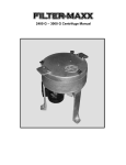
1
Filter unit
30961500 / 09.2013
EN
FAPC 016
Original Operating manual
product illustration>
The specified data serve to describe the product.
Where information is also provided regarding use, it simply represents example
applications and suggestions.
Catalogue information is not warranted.
This information does not relieve the user of the responsibility of making his or
her own judgements and conducting verifications.
Our products are subject to a natural wearing and ageing process.
© All rights reserved by ARGO-HYTOS GmbH, including in the event of
intellectual property uses.
We retain all rights of disposal, such as the right to make copies and distribute
to third parties.
A sample configuration is pictured on the title page. The delivered product may
therefore vary from the illustration.
Original operating manual
Content
Content
1
About this documention.......................................................................................5
1.1
Validity of documentation................................................................................................. 5
1.2
Required and supplementary documentation.................................................................... 5
1.3
Presentation of information ............................................................................................. 6
1.3.1 Safety information............................................................................................................ 6
1.3.2Symbols........................................................................................................................... 7
1.3.3Terms............................................................................................................................... 7
1.3.4Abbreviations................................................................................................................... 7
2
2.1
2.2
2.3
2.4
2.5
2.6
2.7
Safety information...............................................................................................8
About this chapter........................................................................................................... 8
Intended use.................................................................................................................... 8
Improper use.................................................................................................................... 8
Reasonably foreseeable misuse........................................................................................ 8
Qualification of personnel................................................................................................ 9
General safety information............................................................................................... 9
Product- and technology-dependent safety information..................................................... 9
3
General information...........................................................................................10
4
Scope of delivery................................................................................................11
5
5.1
5.2
5.3
5.4
About this product.............................................................................................12
Performance description................................................................................................. 12
Device description.......................................................................................................... 12
Component overview..................................................................................................... 13
Product identification..................................................................................................... 14
6
Transport and storage........................................................................................15
6.1Transport....................................................................................................................... 15
6.2Storage.......................................................................................................................... 16
7Installation.........................................................................................................17
8Commissioning...................................................................................................18
8.1
Before commissioning.................................................................................................... 18
8.2
After switching on.......................................................................................................... 19
8.3
In case of power failure.................................................................................................. 19
9Operation...........................................................................................................20
9.1
Filtering hydraulic fluids when refilling............................................................................ 21
9.2
Filtering fluids in the bypass flow.................................................................................... 22
9.3
Data acquisition............................................................................................................. 23
9.4
Switching of measurement type during filling or cleaning................................................ 23
10
Repair and maintenance....................................................................................24
10.1Maintenance.................................................................................................................. 24
10.2 Maintenance overview................................................................................................... 24
10.2.1 Replace intake strainer................................................................................................... 25
10.3 Replace filter element..................................................................................................... 26
10.3.1 Remove filter element.................................................................................................... 26
10.3.2 Remove filter element from cap...................................................................................... 26
10.3.3 Attach filter element...................................................................................................... 27
10.3.4 Install filter element....................................................................................................... 27
10.3.5 Bleed the filter element.................................................................................................. 28
10.4 Replace pump................................................................................................................ 29
10.4.1 Remove pump................................................................................................................ 30
10.4.2 Install pump................................................................................................................... 30
10.5 Replace motor................................................................................................................ 31
10.5.1 Remove motor............................................................................................................... 31
10.5.2 Install motor.................................................................................................................. 32
10.6 Replace particle monitor OPCom II................................................................................. 33
FAPC 016 | 30961500 / 09.20133/51

10.6.1 Remove particle monitor OPCom II................................................................................. 34
10.6.2 Install particle monitor OPCom II.................................................................................... 34
11Decommissioning...............................................................................................35
12Disassembly........................................................................................................36
13Disposal..............................................................................................................37
14Extension............................................................................................................38
14.1 Optional accessories....................................................................................................... 38
14.1.1 Transport aid / trolley..................................................................................................... 38
14.1.2 Hose extensions............................................................................................................. 38
14.1.3 Intake strainer set.......................................................................................................... 39
15
15.1
15.2
Troubleshooting and fault clearance..................................................................40
Proceed as follows during troubleshooting...................................................................... 40
Fault table..................................................................................................................... 41
16
Technical data....................................................................................................42
16.1Dimensions.................................................................................................................... 42
16.2 Technical data................................................................................................................ 43
16.3 Operating conditions...................................................................................................... 43
16.4 Hydraulic circuit diagram................................................................................................ 44
17Appendix............................................................................................................45
17.1 EC Declaration of Conformity......................................................................................... 45
17.2 Spare parts list............................................................................................................... 46
4/51 |
FAPC 016 | 30961500 / 09.2013
About this documentation
1
About this documentation
1.1
Validity of documentation
This documentation is valid for the following product:
Filter unit FAPC 016
This documentation is intended for installers, operators, service technicians, and plant operators where required.
This documentation contains important information needed to install, transport, commission, operate, use, maintain, and
disassemble the product securely and properly, and in order to clear simple faults.
ff Read this documentation in full, especially Chapter 2 "Safety information" before working with the product.
1.2
Required and supplementary documentation
Do not commission the product until you have received the documentation marked with the book icon and you have
understood and complied with the information therein.
Table 1: Required and supplementary documentation
Title
Document number
Datasheet
80.65.3d
Operating manual
OPCom II
Document type
FAPC 016 | 30961500 / 09.20135/51
About this documentation
1.3
Presentation of information
In order to ensure that you can work with your product quickly and safely, we use uniform safety information, symbols,
terms and abbreviations. These are used in the following sections to aid in comprehension.
1.3.1 Safety information
This documentation provides safety information prior to action sequences in which there is a risk of personal injury or
property damage. The measures described to avert dangers must be complied with.
Warning
Nature and source of the danger
Consequences of non-compliance
ff Measures to avert dangers
ff <Enumeration>
•• Warning sign: calls attention to the danger
•• Warning: indicates the severity of the danger
•• Nature and source of the danger: designates the nature and source of the danger
•• Consequences: describes the consequences in the event of non-compliance
•• Defence: indicates how the danger can be avoided
Table 2: Hazard classes in accordance with ANSI Z535.6-2006
Warning sign, warning
DANGER
Indicates a dangerous situation where death or serious bodily injury will result if not avoided.
WARNING
CAUTION
Indicates a dangerous situation where death or serious bodily injury may result if not
avoided.
NOTE
6/51 |
Meaning
Indicates a dangerous situation in which minor to moderate bodily injury may result if not
avoided.
Property damage: The product or the environment may be damaged.
FAPC 016 | 30961500 / 09.2013
About this documentation
1.3.2Symbols
The following symbols indicate information that is not safety-relevant, but which enhances understanding of the
documentation.
Table 3: Meaning of the symbols
Symbol
Meaning
If this information is not taken into account, the product cannot be used or
operated in optimal fashion.
This symbol specifies that protective goggles should be worn.
This symbol specifies that protective gloves should be worn.
This symbol specifies that safety shoes should be worn.
ff
Single, independent action step
1.3.3Terms
The following terms are used in this documentation:
Table 4: Terms
Term
1.3.4
Meaning
Abbreviations
The following abbreviations are used in this documentation:
Table 5: Abbreviations
Term
Meaning
FAPC
Filter unit with particle monitor
FAPC 016 | 30961500 / 09.20137/51
Safety information
2
Safety information
2.1
About this chapter
The product was manufactured in accordance with generally recognized engineering practice. Nevertheless, there is a
risk of personal injury and property damage if you do not comply with this chapter and the safety information in this
documentation.
ff Please read this documentation carefully and in full before working with the product.
ff Store the documentation so that it is available to all users at all times.
ff Always provide the required documentation when allowing third parties to use the product.
2.2
Intended use
This product is a hydraulic component.
You may use the product as follows:
•• to filter lubes and hydraulic oils during the filling of machines and plants while taking the technical data into account.
•• to filter hydraulic fluids in the bypass flow of machines and plants while taking the technical data into account.
•• For monitoring oil purity when filling machinery and equipment
•• Monitoring of oil purity when cleaning in the bypass flow
The product is intended for professional use only, and not for private use.
The intended use presupposes that you have read and understood this documentation in full, especially Chapter 2
"Safety information".
2.3
Improper use
Any use other than that described in the "Intended use" is improper and is therefore not permitted.
If unsuitable products are installed or used in security-relevant applications, unintended operating states may occur that
may cause personal injury and/or property damage.
For this reason, only use a product in safety-relevant applications if the use in question is explicitly specified and
permitted in the product documentation – for instance, in explosion protection areas or in safety-relevant parts of a
controller (functional safety).
Argo-Hytos AG assumes no liability for damages in the event of improper use. The user alone bears the risks in the event
of improper use.
2.4
Reasonably foreseeable misuse
Pumping of the following media is prohibited:
•• highly flammable liquids, e.g. petrol or thinner (explosion hazard).
The device is not suitable for the extraction of oil sludge and sediment.
The operator alone is liable for damages resulting from improper use.
8/51 |
FAPC 016 | 30961500 / 09.2013
Safety information
2.5
Qualification of personnel
The activities described in this documentation require basic knowledge of engineering and hydraulics, as well as
knowledge of the associated trade terms. In order to guarantee safe use, these activities may therefore only be performed
by appropriate technicians or by a trained person under the guidance of a technician.
A technician refers to someone who is able to evaluate the tasks s/he is assigned, recognise potential hazards and take
suitable safety measures on the basis of his/her professional training, general knowledge and experience, and knowledge
of the applicable regulations. A technician must comply with the relevant technical rules of the industry.
2.6
General safety information
•• Please comply with applicable regulations governing accident prevention and environmental protection.
•• Please comply with the safety regulations and provisions of the country in which the product is used/employed.
•• Only use Argo-Hytos products that are in technically perfect condition.
•• Observe all instructions on the product.
•• Individuals who install, operate, disassemble or maintain Argo-Hytos products must not be under the influence of
alcohol, or other drugs or medications that impair reaction time.
•• Please only use accessories and spare parts approved by the manufacturer in order to eliminate the risk of personal
injury posed by inappropriate spare parts.
•• Please comply with the technical data and environmental conditions specified in the product documentation.
•• If unsuitable products are installed or used in safety-relevant applications, unintended operating states may occur that
may cause personal injury and/or property damage. For this reason, only use a product in safety-relevant applications if
the use in question is explicitly specified and permitted in the product documentation.
•• You may only commission the product once it has been determined that the end product (e.g. a machine or plant) in
which the Argo-Hytos products are installed satisfy the country-specific provisions, safety regulations and standards.
2.7
Product- and technology-dependent safety information
CAUTION
Leaking hydraulic oil!
Environmental hazard/risk of slipping!
ff In the event of a hydraulic oil leak, immediately cover the oily surface with an oil-binding agent.
ff Then immediately dispose of the oil-binding agent in accordance with country-specific environmental regulations.
Leaking hydraulic oil!
Ignition hazard!
Risk of the electrostatic discharge due to poorly conducting hydraulic fluid
ff If the electrical conductivity of the hydraulic fluid is not known, please contact the manufacturer of the hydraulic
fluid.
Risk of burns!
Contact temperatures in accordance with DIN EN563 (3) and DIN EN13202 (4) may be exceeded during operation.
ff Let the filter unit cool off before touching it.
FAPC 016 | 30961500 / 09.20139/51
General information
3
General information
for the avoidance of property and product damages
CAUTION
Risk due to improper handling!
Property damage!
ff The filter unit may only be used in accordance with Section 2.2 "Intended use".
Leakage or spillage of hydraulic fluid!
Environmental pollution and groundwater contamination!
ff Use an oil-binding agent to bind the leaked hydraulic oil.
Risk of burns!
Contact temperatures in accordance with DIN EN563 (3) and DIN EN13202 (4) may be exceeded during operation.
ff Allow the filter unit to cool off before touching it.
Contamination by liquids and debris!
Premature wear, functional impairments! Risk of damage! Property damage!
ff Ensure cleanliness during installation in order to prevent debris such as welding beads or metal shavings from
entering the hydraulic lines and causing wear and malfunctions in the product.
ff Make sure the connections, hydraulic lines and fittings (e.g. measurement devices) are free of dirt and chips.
ff Prior to commissioning, verify that all hydraulic and mechanical connections are connected and tight, and that all of
the connectors' gaskets and screw connections are correctly installed and undamaged.
ff Use residue-free industrial wipes in order to remove lubricants and other contamination.
ff Make sure that the connections, hydraulic lines and fittings are clean.
ff Make sure that no contaminants penetrate while closing the connections.
ff Make sure that no cleaning agents enter the hydraulic system.
ff Do not use steel wool or fraying cloths for cleaning.
ff Do not use hemp as a gasketing material.
Improper cleaning!
Premature wear, functional impairments! Risk of damage! Property damage!
ff Close all openings using suitable safety screw connections to prevent cleaning agents from penetrating.
ff Do not use any aggressive cleaning agents for cleaning. Clean the product using a suitable cleaning fluid.
ff Do not use a pressure washer.
ff Do not use compressed air for cleaning around functional interfaces, e.g. in the area of gaskets.
10/51 |
FAPC 016 | 30961500 / 09.2013
Scope of delivery
4
Scope of delivery
The scope of delivery includes the following:
•• 1 filter unit FAPC 016
•• 1 operating manual
FAPC 016 | 30961500 / 09.201311/51
About this product
5
About this product
5.1
Performance description
Filter unit FAPC 016 is a mobile filter system for filtering hydraulic fluids and lubricants with a viscosity of 15 mm2/s (min.
in continuous operation) - 150 mm2/s in the bypass flow.
(300 mm2/s max. during short-term operation).
Separate installation in the bypass flow or cooling circuit is also possible in order to perform fine filtration and to relieve
the main flow filter, as is the filtration of fresh oil and cleaning (rinsing) of contaminated plants in order to protect the
components and systems against wear.
The volume flow is 16 l/min.
The operating temperature range is from 0°C to 60°C.
5.2
Device description
Filter unit FAPC 016 consists of a support frame in which a filter pump unit is integrated. It consists of an electronically
operated filter pump with a replaceable filter element and a manometer as a maintenance indicator. The on-off switch is
located on the control box of the pump motor. The suction hose is connected at the suction side connection of the pump
and the pressure hose is connected at the main filter outlet.
The particle monitor OPCom II can be configured and programmed directly on the device.
Measurement data can be transferred to a PC by means of an RS232 interface and then saved for processing on the PC.
12/51 |
FAPC 016 | 30961500 / 09.2013
About this product
5.3
Component overview
Fig. 1: Component overview
1 Power cord
9 Catch basin
2 Particle monitor OPCom II
10 Suction cup
3 Pressure hose
11 Circuit breaker
4 Valve housing with 1 bar valve
12 Electric motor
5 Clogging indicator
13 RS232 interface
6 Three-way stopcock / switching lever
14 Suction hose
7 Protective strainer
15 Filter housing with filter element
8 Discharge pipe
16 Filter cover
FAPC 016 | 30961500 / 09.201313/51
About this product
5.4
Product identification
Fig. 2: Rating plate
14/51 |
1 Maximum pressure
4 Year of construction
2 Nominal volume flow
5 Type designation
3 Filter fineness
6 Address
FAPC 016 | 30961500 / 09.2013
Transport and storage
6
Transport and storage
6.1
Transport
CAUTION
Unit may fall during incorrect transport!
Injuries! Property damage!
ff Given that the device weighs 22 kg, if carried manually, this should absolutely be performed by two persons.
ff Wear safety shoes while transporting the filter unit.
Fig. 3: Transport using barrows
The compact design enables easy transport of the FAPC 016 filter unit – even to inaccessible parts of hydraulic plants.
Hoses and electrical cables can be attached to the device. The device can be transported and operated both standing
upright and lying flat.
Please note the instructions in Chapter 2 "Basic safety information".
ff When using mobile transport aids, make sure the unit is stably positioned (danger of tipping).
ff During transport, affix the suction and pressure hoses in the brackets provided for this purpose in order to prevent
possible leakage of residual oil.
FAPC 016 | 30961500 / 09.201315/51
Transport and storage
6.2
Storage
Filter unit FAPC 016 should be stored in an enclosed space in order to protect it against moisture and condensation.
DANGER
Risk of injury!
Risk of chemical reactions!
Chemical substances in the immediate vicinity of the filter unit may react and lead to destruction of the device and
personal injury to persons in the immediate vicinity of the device.
ff Storage in the immediate vicinity of chemically active substances such as acids, bases, salts, organic solvents and
rechargeable batteries is prohibited.
The ambient temperature during storage of filter unit FAPC 016 should be between +5°C and +30°C with a maximum
humidity of 80%.
Prior to a storage period to exceed six months, the device should be filled with oil in order to protect it against rust.
16/51 |
FAPC 016 | 30961500 / 09.2013
Installation
7
Installation
WARNING
Incorrect energy supply!
Danger to life! Risk of injury!
ff Always comply with country-specific regulations.
Before commissioning, have a qualified electrician check whether:
ff line voltage corresponds to motor voltage indicated on the rating plate,
ff the power source is appropriately fused,
ff the line cross-section is sufficiently dimensioned,
ff cables and the connection to the power source are in perfect condition.
After connection, for 3-phase AC motors, check whether:
ff the motor's direction of rotation corresponds to the direction of the rotation arrow on the motor during power-up, or
have this changed by a qualified electrician.
In particular, proceed according to the following steps:
ff Connect the 230 V power plug to the local power supply.
FAPC 016 | 30961500 / 09.201317/51
Commissioning
8
Commissioning
8.1
Before commissioning
ff Do not commission the device until you have read and understood the operating manual.
ff You must comply with the information regarding proper use, operating conditions and the technical data.
ff The unit must be positioned so as to prevent the risk of tipping and so that vibrations are largely absorbed.
ff The unit must be positioned so that cables and hoses are outside of the range of movement of operating personnel
(tripping hazard).
ff If no hydraulic oil is sucked in during commissioning, turn off the device, open the cap on the filter housing and add
approximately 0.3 litres of hydraulic oil.
ff The hydraulic oil to be filtered must be compatible with the previously filtered hydraulic oil. If this is not the case, the
filter unit must be cleaned, and the filter element replaced (see Filter replacement).
ff When using the hoses, make sure that it is impossible for the hoses to fall out of the tank during unsupervised
operation
ff The suction pipe and discharge pipe must be submerged far enough below the liquid level for oil to be drawn.
ff The hydraulic fluid must be water-free (no oil turbidity).
ff Free water in the oil distorts measurement results.
ff Close the filter housing cover properly.
ff Turn the cover by hand as far as it will go; there may be a gap that remains visible between the cover and the
housing (see fig. 3).
Fig. 4: Gap on filter cover
18/51 |
FAPC 016 | 30961500 / 09.2013
Commissioning
8.2
After switching on
ff For 3-phase AC motors, check whether the motor's direction of rotation corresponds to the direction of rotation
arrow on the motor during power-up, or have this changed by a qualified electrician.
ff Check the filter unit for leaks.
ff Check whether the device is properly vented. To do so, open the Allen screw on the cover slightly until oil comes
through. After that, retighten the Allen screw.
Air bubbles in the oil distort the measurement result.
8.3
In case of power failure
In order to prevent unintended start of the unit, always switch the unit off and disconnect the power plug.
FAPC 016 | 30961500 / 09.201319/51
Operation
9
Operation
CAUTION
Hazards posed by spilled oil!
Injuries! Risk of slipping!
ff If oil leaks, the oil-covered area must be blocked off immediately and covered with an oil-bonding medium (risk of
slipping).
Static charge!
Sparking!
ff When using low-conductivity hydraulic oils or lubricants, there is a risk of static charges.
If this is the case, please consult the manufacturer.
NOTE
Damage to filter unit as a result of missing or defective intake strainer!
Property damage!
ff The intake strainer must be checked in accordance with the maintenance periods and replaced as required.
Inaccurate measurement results!
Incorrect measurements!
ff The measured values from the first five minutes should not be taken into account, as the particle counter needs to
initialise, and the hydraulic circuit must stabilise (air bubbles, flushing, etc.).
ff The suction side of the filter unit has a protective suction strainer that needs to be maintained on a regular basis.
A missing protective strainer may lead to damage to the pump. (see spare parts list for order number)
ff The manufacturer accepts no liability if the protective strainer is removed.
20/51 |
FAPC 016 | 30961500 / 09.2013
Operation
9.1
Filtering hydraulic fluids when refilling
1. Attach the filter unit to a power source.
2. Insert the suction strainer into the oil barrel.
3. Insert the discharge pipe into a tank (e.g. hydraulic tank).
NOTE
Incorrect insertion of discharge pipe!
ff Make sure that the discharge pipe is below the fluid surface.
4. Switch on the filter unit using the on/off switch (circuit breaker).
5. Check the oil flow for potentially insufficient immersion depth of the suction pipe in the oil tank.
NOTE
Incorrect insertion of discharge pipe!
ff At the beginning of filtration, filling the filter unit may take a few seconds.
6. Use the clogging indicator to check element contamination at the operating temperature of the medium in question.
7. Monitor the fill level on the machine or equipment, and switch off the filter unit using the circuit breaker once the
desired capacity has been reached.
8. Return the suction strainer and discharge pipe to the respective brackets on the filter unit.
FAPC 016 | 30961500 / 09.201321/51
Operation
9.2
Filtering fluids in the bypass flow
1. Attach the filter unit to a power source.
2. Place the suction strainer in the tank of the machinery or equipment (e.g. hydraulic tank).
3. Place the discharge pipe in the tank of the machinery or equipment (e.g. hydraulic tank).
NOTE
Incorrect insertion of discharge pipe!
ff At the beginning of filtration, filling the filter unit may take a few seconds.
4. Switch on the filter unit using the on/off switch (circuit breaker).
5. Check the oil flow for potentially insufficient immersion depth of the suction pipe in the oil tank.
NOTE
Incorrect insertion of discharge pipe!
ff At the beginning of filtration, filling the filter unit may take a few seconds.
6. Use the clogging indicator to check element contamination at the operating temperature of the medium in question.
7. Once filtration is complete, pull the discharge pipe out of the tank of the machinery or equipment (e.g. hydraulic
tank) and draw in air for a maximum of 30 seconds.
This returns residual oil from the filter housing and the lines above oil level into the tank of the machinery or
equipment via the discharge pipe.
8. Switch off the filter unit using the circuit breaker.
9. Return the suction strainer and discharge pipe to the respective brackets on the filter unit.
NOTE
Maximum cleaning power reached!
ff In order to prevent an oil flow short circuit, the distance between the suction and pressure connections should be
as great as possible.
Incorrect measurement results!
ff Make absolutely sure that the device is properly vented.
22/51 |
FAPC 016 | 30961500 / 09.2013
Operation
9.3
Data acquisition
Filter unit FAPC 016 is equipped with a data memory that can store up to 3000 results.
Once the storage capacity is reached, the last measured value is saved, while the oldest measured value is simultaneously
overwritten.
NOTE
A description of installation and data transmission is available in the OPCOM II user manual.
1. Connect a data cable to the RSR232 socket (fig. 1 pos. 13).
2. Connect the plug to a PC or laptop with the appropriate software installed.
NOTE
The relevant software can be downloaded from www.argo-hytos.com.
The stored results are transferred to the hard disk of the connected PC or laptop, and can be stored there.
9.4
Switching of measurement type during filling or cleaning
When monitoring the purity class, a ball valve can be used to switch between ‘downstream of filter’ (e.g. when filling
equipment) and ‘upstream of filter’ (e.g. when cleaning out oil fillings).
Switch positions are changed using the attached three-way stopcock (fig. 1 pos. 6).
Fig. 5: Three-way stopcock
•• Switch position upstream of filter
–– Horizontal lever position
–– Oil purity is monitored during the cleaning process
Switch position downstream of filter
–– Vertical lever position
–– Oil purity is monitored during the filling process
FAPC 016 | 30961500 / 09.201323/51
Repair and maintenance
10 Repair and maintenance
DANGER
Danger to life!
Risk of electrical shock!
ff Switch off the device and pull out the plug during repair work.
CAUTION
Leaking hydraulic oil!
Environmental hazard/risk of slipping!
ff Before maintenance and servicing, empty the device completely!
ff In the event of a hydraulic oil leak, immediately cover the oily surface with an oil-binding agent.
ff Then immediately dispose of the oil-binding agent in accordance with country-specific environmental regulations.
Leaking hydraulic oil!
Ignition hazard!
Risk of the electrostatic discharge due to poorly conducting hydraulic fluid
ff If the electrical conductivity of the hydraulic fluid is not known, please contact the manufacturer of the hydraulic
fluid.
Risk of burns!
Contact temperatures in accordance with DIN EN563 (3) and DIN EN13202 (4) may be exceeded during operation.
ff Let the filter unit cool off before touching it.
NOTE
Functional impairment!
Dirt entering the pump!
Filter unit functionality is no longer assured.
ff During repair work, all components coming into contact with the hydraulic medium must be kept free of dirt and
chips.
10.1 Maintenance
10.2 Maintenance overview
The filter unit requires no maintenance, with the exception of the filter element and the intake strainer.
Maintenance work
Order no.
Maintenance period
Check/replace filter element
V7.1220-113 (3 µm)
As soon as the clogging indicator enters the red range, given
permissible viscosity
Check/replace intake strainer
FA 016.0110
4 times a year or
in the event of abnormalities (low volume flow when filter
element is cleaned, operating noise too loud).
24/51 |
FAPC 016 | 30961500 / 09.2013
Repair and maintenance
10.2.1 Replace intake strainer
NOTE
Damage to filter unit as a result of missing or defective intake strainer!
Property damage!
ff The intake strainer must be checked in accordance with the maintenance periods and replaced as required.
Fig. 6: Replace intake strainer
1. Loosen the hose clamp (1).
2. Pull the intake strainer (5) together with the suction cup (4) and the disc (3) off the suction hose (2).
3. Clean the intake strainer (5) with cleaning grade petrol or diesel fuel.
NOTE
If damaged, replace the intake strainer (5) (order no. FA 016.0110).
4. Place the intake strainer (5) with the suction cup (4) and the disc (3) - as shown above - on the suction hose (2).
5. Secure the hose clamp (1).
FAPC 016 | 30961500 / 09.201325/51
Repair and maintenance
10.3 Replace filter element
1. Pump the filter element until it is empty
(see Chapter 9.2 "Filtering fluids in the bypass circuit" Paragraph 7)
2. Switch off the filter unit using the on/off switch (circuit breaker) and remove the power cord.
CAUTION
Risk of burns!
Contact temperatures in accordance with DIN EN563 (3) and DIN EN13202 (4) may be exceeded during operation.
ff Let the filter unit cool off before touching it.
10.3.1 Remove filter element
Fig. 7: Remove filter element
1. Unscrew the housing cover (1) anti-clockwise.
2. Carefully pull cap (1) with filter element (2) out of the filter tube.
(The filter element is mounted on the cap. Let the outflowing oil drip into the housing.)
10.3.2 Remove filter element from cap
Fig. 8: Remove filter element
1. Slide the filter element on the cover in the direction of arrow 1 and remove in the direction of the arrow 2.
2. Dispose of the filter element in accordance with country-specific environmental regulations (waste code: Oil filter 16
01 07).
26/51 |
FAPC 016 | 30961500 / 09.2013
Repair and maintenance
10.3.3 Attach filter element
Fig. 9: Connect filter element
1. Check the filter element type number.
Does the laser inscription on the filter element match the information on the rating plate or in the instruction
manual?
2. Mount the filter element in the direction of arrow 2, and snap into place in the direction of arrow 1.
10.3.4 Install filter element
Fig. 10: Install filter element
1. Always replace the O-ring in the cover when replacing the filter element (O-ring order no. N007.1175, included with
replacement filter elements).
2. Carefully insert the cap (1) with the filter element (2) into the filter tube.
3. Turn the cover by hand as far as it will go. A gap may remain visible between the cover and the filter pipe (see
Chapter 8.1 "Before commissioning" / fig. 3) .
FAPC 016 | 30961500 / 09.201327/51
Repair and maintenance
10.3.5 Bleed the filter element
Fig. 11: Bleed the filter unit
1. Open the bleed screw (1).
2. Insert the power cord and return the filter unit into operation.
When oil begins to run out from the vent opening, reseal the vent opening by tightening the bleed screw (1).
3. Check to make sure that the ventilation slot of the electric motor is not contaminated, and remove any deposits.
4. Return the device into operation.
5. Check the filter housing for leaks after commissioning.
28/51 |
FAPC 016 | 30961500 / 09.2013
Repair and maintenance
10.4 Replace pump
DANGER
Danger to life!
Risk of electrical shock!
ff Pull out the mains plug prior to uninstallation. Deinstallation should only be performed by qualified electricians.
Risk of injury!
Risk of injury in the event of incorrect handling!
ff Deinstallation should only be performed by trained personnel.
CAUTION
Risk of burns!
Contact temperatures in accordance with DIN EN563 (3) and DIN EN13202 (4) may be exceeded during operation.
ff Let the filter unit cool off before touching it.
Fig. 12: Replacement of motor and pump
FAPC 016 | 30961500 / 09.201329/51
Repair and maintenance
10.4.1 Remove pump
1. Loosen the hex nuts (pos. 8).
2. Remove the component "Filter tube and housing" (pos. 1) together with the attached measuring sensor by pulling
upwards.
3. Loosen the pump plate (pos. 5) with the wheel set (consisting of an outer rotor and inner rotor, pos. 4) from the
motor (pos. 9) by pulling gently upward.
4. Dispose of the pump plate, the wheel set and the O-rings in accordance with country-specific environmental
regulations.
NOTE
When replacing the pump, the O-rings (pos. 2 & pos. 6) must absolutely be replaced with new O-rings.
The order number is indicated in the spare parts list.
10.4.2 Install pump
1. Fit the outer rotor and inner rotor (pos. 4) together and place them in the recess provided in the pump plate for this
purpose.
It can be installed in any position.
2. Lubricate the O-rings (pos. 2 & pos. 6) and place them in the O-ring grooves in the pump plate provided for this
purpose.
3. Place the pre-assembled pump plate (pos. 5 with pos. 4) on the motor (pos. 9).
In so doing, guide the feather key of the motor shaft (pos. 7) into one of the four feather key grooves of the inner
rotor.
NOTE
When pressing the pump plate onto the motor, make sure that the O-ring (pos. 6) does not slip out of the O-ring groove
and become damaged between the motor and pump plate.
The hole for the pin (anti-rotation lock pos. 3) must be opposite the terminal box (motor pos. 9).
4. Wet or fill the wheel sets of the pump with oil.
5. Fit the component "filter tube with housing" (pos. 1) back together with the pump plate and motor.
NOTE
When installing the filter pipe, make sure that the O-ring (pos. 2) does not slip out of the O-ring groove and become
damaged between the pump plate (pos. 5) and the housing (pos. 1).
6. Secure the component using the nuts (pos. 8) (tightening torque 15+2 Nm).
The device can be returned to operation.
If no oil is drawn during commissioning, open the cover on the filter housing and fill with approximately 300 ml of oil.
30/51 |
FAPC 016 | 30961500 / 09.2013
Repair and maintenance
10.5 Replace motor
DANGER
Danger to life!
Risk of electrical shock!
ff Pull out the mains plug prior to uninstallation. Deinstallation should only be performed by qualified electricians.
Risk of injury!
Risk of injury in the event of incorrect handling!
ff Deinstallation should only be performed by trained personnel.
CAUTION
Risk of burns!
Contact temperatures in accordance with DIN EN563 (3) and DIN EN13202 (4) may be exceeded during operation.
ff Let the filter unit cool off before touching it.
10.5.1 Remove motor
1. Loosen the hex nuts (pos. 8).
2. Remove the component "Filter tube and housing" (pos. 1) together with the attached measuring sensor by pulling
upwards.
3. Loosen the pump plate (pos. 5) with the wheel set (consisting of an outer rotor and inner rotor, pos. 4) from the
motor (pos. 9) by pulling gently upward.
4. Loosen the motor (9) from the bracket.
5. Dispose of the motor in accordance with country-specific environmental regulations.
NOTE
When replacing the pump, the O-rings (pos. 2 & pos. 6) must absolutely be replaced with new O-rings.
The order number is indicated in the spare parts list.
FAPC 016 | 30961500 / 09.201331/51
Repair and maintenance
10.5.2 Install motor
1. Mount the motor (9) onto the bracket.
2. Lubricate the O-rings (pos. 2 & pos. 6) and place them in the O-ring grooves in the pump plate provided for this
purpose.
3. Place the pre-assembled pump plate (pos. 5 with pos. 4) on the motor (pos. 9).
In so doing, guide the feather key of the motor shaft (pos. 8) into one of the four feather key grooves of the inner
rotor.
NOTE
When pressing the pump plate onto the motor, make sure that the O-ring (pos. 6) does not slip out of the O-ring groove
and become damaged between the motor and pump plate.
The hole for the pin (anti-rotation lock pos. 3) must be opposite the terminal box (motor pos. 9).
4. Wet or fill the wheel sets of the pump with oil.
5. Fit the component "filter tube with housing" (pos. 1) back together with the pump plate and motor.
NOTE
When installing the filter pipe, make sure that the O-ring (pos. 2) does not slip out of the O-ring groove and become
damaged between the pump plate (pos. 5) and the housing (pos. 1).
Secure the component using the nuts (pos. 8) (tightening torque 15+2 Nm).
The device can be returned to operation.
If no oil is drawn during commissioning, open the cover on the filter housing and fill with approximately 300 ml of oil.
32/51 |
FAPC 016 | 30961500 / 09.2013
Repair and maintenance
10.6 Replace particle monitor OPCom II
DANGER
Danger to life!
Risk of electrical shock!
ff Pull out the mains plug prior to uninstallation. Deinstallation should only be performed by qualified electricians.
Risk of injury!
Risk of injury in the event of incorrect handling!
ff Deinstallation should only be performed by trained personnel.
CAUTION
Risk of burns!
Contact temperatures in accordance with DIN EN563 (3) and DIN EN13202 (4) may be exceeded during operation.
ff Let the filter unit cool off before touching it.
FAPC 016 | 30961500 / 09.201333/51
Repair and maintenance
10.6.1 Remove particle monitor OPCom II
Fig. 13: Replace measurement sensor
6. Disconnect the power cable on the bottom of OPCom II (cable not shown).
7. Undo the threaded elbow at the inlet (1) and at the outlet (2).
8. Loosen the Allen screws (4).
9. Lift off the particle monitor (3).
DANGER
Danger to life!
Risk of electrical shock!
ff Pull out the mains plug prior to uninstallation. Uninstallation should only be performed by qualified electricians.
10.6.2 Install particle monitor OPCOM II
Installation is performed (as described above) in reverse order.
34/51 |
FAPC 016 | 30961500 / 09.2013
Decommissioning
11 Decommissioning
DANGER
Danger to life!
Risk of electrical shock!
ff Pull out the mains plug prior to uninstallation. Deinstallation should only be performed by qualified electricians.
Risk of injury!
Risk of injury in the event of incorrect handling!
ff Deinstallation should only be performed by trained personnel.
Final decommissioning and disposal requires complete uninstallation of the entire power supply and mechanical
components, and disposal of the hydraulic media remaining in the device.
During uninstallation and disposal, all country-specific safety and environmental regulations must be complied with.
FAPC 016 | 30961500 / 09.201335/51
Disassembly
12 Disassembly
The filter unit does not need to be disassembled.
36/51 |
FAPC 016 | 30961500 / 09.2013
Disposal
13 Disposal
Careless disposal of filter unit FAPC 016 and the hydraulic fluid may lead to environmental pollution.
For this reason, please dispose of the filter unit and hydraulic fluid in accordance with applicable national regulations.
Please dispose of hydraulic fluid residues in accordance with the safety data sheets that apply to these hydraulic fluids.
FAPC 016 | 30961500 / 09.201337/51
Extension
14 Extension
14.1 Optional accessories
14.1.1 Transport aid/trolley
Order no. FA 016-1760
For easy transport of filter unit FAPC 016 it is possible to hook a trolley onto the standing device. This allows effortless
transport even over long distances.
Fig. 14: Optional accessory "Trolley"
14.1.2 Hose extensions
On request, ARGO-HYTOS will also provide hose extensions cut to your specifications.
38/51 |
FAPC 016 | 30961500 / 09.2013
Extension
14.1.3 Intake strainer set
Order no. FA 016.1775
Fig. 15: Option "Intake strainer set"
The intake strainer set FA 016.1775 guarantees pump protection when it is not possible to use the existing intake strainer
on the suction hose. This is the case if the filter unit needs to be connected to hydraulic equipment using a quick release
coupling or a ball valve, or if the tank opening is not sufficiently large.
The suction strainer set FA 016.1775 consists of a suction strainer element 280 μm (2), a safety device (3), a connection
housing with O-ring (4) and a connecting piece (1).
The intake strainer set FA 016.1775 is constructed in such a manner that the DN 25 hose connection can be rotated
360° and thereby adapted to the hose feed.
FAPC 016 | 30961500 / 09.201339/51
Troubleshooting and fault clearance
15 Troubleshooting and fault clearance
15.1 Proceed as follows during troubleshooting
ff Form an understanding of the product's functionality in the context of the overall system.
ff Try to ascertain whether the product provided the required functionality in the overall plant before the error occurred.
ff Try to detect changes in the overall system in which the product is installed:
–– Have the operating conditions or operating range of the product changed?
–– Have changes (e.g. conversions) or repairs been made to the overall system (machine/plant, electric system,
controller) or to the product? If so: Which ones?
–– Was the product or machine operated as intended?
–– How does the fault manifest itself?
ff Form a clear understanding of the cause of the error. Ask the immediate user or machine operator as needed.
40/51 |
FAPC 016 | 30961500 / 09.2013
Troubleshooting and fault clearance
15.2 Fault table
Fault table
Table 6: Fault table
Problem/fault
Potential cause
Clearance
Electric motor does not turn on
during commissioning
Electrical cable or mains plug
defective
Have cable replaced by a qualified electrician
No line voltage
Establish line voltage and/or activate electrical fuse
On/off switch defective
Replace on/off switch
Motor defective
Replace motor (repair at manufacturer)
Pump defective
Replace pump (repair at manufacturer)
Viscosity too high (medium)
Heat the oil
Electric motor switches off during
operation
Electric motor overheated
Let motor cool off, clean any contaminated ventilation
slits
Pump blocked
Replace pump (repair at manufacturer)
Volume flow clearly too low
Filter element contaminated
Replace filter element
Intake strainer contaminated
Replace/clean intake strainer
Viscosity too high
Heat the medium
Suction head too high
Adjust suction head
Leak on the suction side
Replace suction hose or seal connection sites
(retighten)
Pump wear
Replace pump (repair at manufacturer)
Filter element contaminated
Replace filter element
Intake strainer contaminated
Replace/clean intake strainer
Viscosity too high
Heat the medium
Suction head too high
Adjust suction head
Leak on the suction side
Replace suction hose or seal connection sites
(retighten)
Pump wear
Replace pump
Filter unit standing on vibrationsensitive surface (e.g. sheet metal)
Improve site conditions
Leak on the suction side
Replace suction hose or seal connection sites
(retighten)
Unit pumped empty (on refilling)
Prime the unit (0.3 l)
Intake strainer clogged
Clean/replace intake strainer
Shaft seal leaky
Replace motor or repair by the manufacturer
Residual oil on the housing after
filter element replacement
Clean filter unit
Leaky screw connector
Check screw connectors, re-tighten and/or seal as
needed
Operating noise too loud
Pump does not prime
Oil on the fan wheel cover,
Oil leaking out of terminal box
FAPC 016 | 30961500 / 09.201341/51
Technical data
16 Technical data
16.1 Dimensions
Fig. 16: Dimensions
42/51 |
FAPC 016 | 30961500 / 09.2013
Technical data
16.2 Technical data
Table 7: Technical data
Nominal flow rate
l/min (50 Hz)
16
l/min (60 Hz)
19.2
Pressure limiting valve
bar
5 ± 0,5
Max. operating pressure
bar
4
ß5(c) ≥ 200
Filter element
V7.1220-13
Clogging indicator
Manometer DG 200-17
green: 0 - 2.7 bar
red: from 2.7 bar
Suction side
Hose DN 19 with intake strainer
Pressure side
Hose DN 19 with discharge pipe
Electric drive
1-phase 230 V motor
230V; 50Hz; 0.45kW
230V; 60 Hz; 0.54 kW
Tare weight
kg
approx. 24
Sound power level
db(A) max.
68 (under operating conditions permitted for continuous operation)
16.3 Operating conditions
WARNING
Risk of burns!
Contact temperatures in accordance with DIN EN563 (3) and DIN EN13202 (4) may be exceeded during operation.
ff Let the filter unit cool off before touching it.
NOTE
Variable viscosity!
The viscosity of a medium is always temperature-dependent.
Electric drive 1~230 V 50/60 Hz
mm²/s (min. continuous operation)
15
mm²/s (max. continuous operation) 150
Permissible temperature range
Allowable suction heads
Hydraulic fluid °C
10...65
Ambient °C
0...60
m (max.) first use
0.5
m (max.) operating state
1.5
Resistance to media
Hydraulic fluids based on mineral
oil, rapeseed oils and synthetic
esters.
Working position
Any position, standing preferred
FAPC 016 | 30961500 / 09.201343/51
Technical data
16.4 Hydraulic circuit diagram
Fig. 17: Hydraulic circuit diagram
44/51 |
1 Filter
7 Suction filter
2 Clogging indicator
8 Discharge pipe
3 Pressure limiting valve
9 Pressure hose
4 Motor
10 Measurement sensor OPCom II
5 Pump
11 Pressure holding valve
6 Suction hose
12 Three-way stopcock
FAPC 016 | 30961500 / 09.2013
Appendix
17 Appendix
17.1 EC Declaration of Conformity
We, the company,
ARGO-HYTOS GmbH
Industriestraße 9
76703 Kraichtal-Menzingen, Germany,
declare on our sole responsibility that the products in the model series
Filter unit FAPC 016
to which this declaration pertains are in conformity with the following directives:
Directive 2006/42/EC (Machinery Directive)
Directive 2004/108/EC (EMC Directive)
Conformity with the directives is assured through compliance with the following standards:
DIN EN 809
Pumps and Pump Units for Liquids
DIN EN 60204-1 (VDE 0113-1: 2007-06)
Safety of machinery - Electrical equipment of machines - Part 1 General requirements (IEC 60204-1:2005, modified);
German version EN 60204-1:2006
Kraichtal,
Dr Marcus FischerThomas Weiser
Technical DirectorDocumentation Officer
FAPC 016 | 30961500 / 09.201345/51
Appendix
17.2 Spare parts list
Fig. 18: Spare parts drawing 1
46/51 |
FAPC 016 | 30961500 / 09.2013
Appendix
Fig. 19: Spare parts drawing 2
FAPC 016 | 30961500 / 09.201347/51
Appendix
Fig. 20: Spare parts drawing 3
48/51 |
FAPC 016 | 30961500 / 09.2013
Appendix
Fig. 21: Spare parts drawing 4
FAPC 016 | 30961500 / 09.201349/51
Appendix
Table 8: Spare parts list
Serial
no.
Designation
Pcs.
Order no.
Comment
1
Filter element
1
V7.1220-113 14311300
2
Strainer
1
S9.0205-02 1507740
3
Manometer
1
DG 200-17 14229800
4
Ball valve G¼“
1
FA 016.0725 14218300
5
Cover, complete
1
FNA 008.1280 14136900
6
Pump plate, complete 1
FNA 008.1230 11898400
Consisting of pump plate, outer rotor and
inner rotor
7
Rotor, complete
1
FNA 008.1730 15110300
Consisting of outer rotor and inner rotor
8
Basin
1
FA 016.0101 14247500
9
Spiral pipe
1
30880100
10
Set of seals
1
FAPC 016.1720 15110200
Consisting of positions 10.1 to 10.5
11
Valve, complete
1
FAPC 016.1710 15110100
Consisting of valve and valve housing
Spare parts OPCom II
12
OPCom II
1
SPCO 300-1000 27394501
13
Hose
1
FA 016.0735 o.Z. 14219700
14
Power supply unit
1
30881300
for FAPC 016-2105/ 30707700
Spare parts motor
15
Motor
1
FA 016.1700 17068500
for FAPC 016-2105/ 30707700
16
Cable, complete
1
FA 016.1201 11919900
Consisting of cable and plug for FAPC
016-2105/ 30707700
17
Installation kit
1
FA 016.1790 17805800
Consisting of screws, nuts, rubber buffers
and spacer
Spare parts pressure hose
18
Pipe
1
FA 016.0103 13448700
19
Hose clamp
4
DIN 3017 11889400
20
Pressure hose
1
FA 016.0107 11905300
21
Hose nipple
1
FA 016.0736 14219800
Spare parts suction hose
50/51 |
22
Strainer, complete
1
FA 016.1780 15110400
23
Suction hose
1
FA 016.0106 11904900
24
Hose nipple
1
FA 016.1401 11887400
Consisting of strainer, disc and suction
cup
FAPC 016 | 30961500 / 09.2013
We produce fluid power solutions
ARGO-HYTOS GmbH · Industriestraße 9 · 76703 Kraichtal-Menzingen · Germany
Tel: + +49 7250-0 · Fax: +49 7250 76-199 · [email protected] · www.argo-hytos.com
Subject to change
30961500 / 09.2013