1
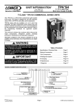
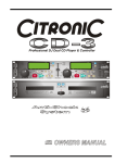
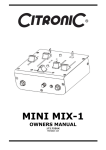
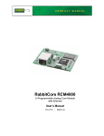
Active Crossovers CX23 CX34 170.929 170.932 User Manual Features: Linkwitz-Riley crossover filters Mono/Stereo operating modes Switchable Phase Invert Switchable Butterworth 40Hz low cut Balanced or unbalanced XLR connections www.citronic.com Introduction: Thank you for choosing a Citronic active crossover. This product has been designed to give accurate control for a multi-amplifier sound reinforcement system. In order to achieve the best results from this equipment and avoid damage through misuse, please read and follow these instructions and retain for future reference. Warning: To prevent the risk of fire or electric shock, do not expose any part of the unit to rain or moisture. If liquids are spilled on the surface, stop using immediately, allow unit to dry out and have checked by qualified personnel before further use. Avoid impact, extreme pressure or heavy vibration to the unit. There are no user serviceable parts inside the crossover – refer all servicing to qualified service personnel. Safety Check that the supplied mains lead is in good condition and the supply voltage is correct. Ensure signal leads are of good condition and connected to appropriate inputs/outputs Do not allow any foreign particles to enter the console through control apertures or connector apertures Placement Keep out of direct sunlight and away from heat sources. Keep away from damp or dusty environments. When rack-mounting, avoid placing heavy units above the unit and ensure all connectors are accessible Cleaning Use a soft cloth with a neutral detergent to clean the casing as required Use a soft brush to clear debris from the control surface Do not use strong solvents for cleaning the unit. Front Panel 1. 2. 3. 4. 5. 6. 7. 8. 9. 10. 11. 12. 13. Input gain: Channel A Low Cut filter: Channel A Low/High X-over Frequency: Channel A Low/High - Low/Mid crossover Frequency: Channel A Low/Mid - Mid/High crossover Frequency: Channel A Low output gain: Channel A Low output phase switch: Channel A Mid or Low-mid output gain: Channel A Mid or Low-mid output phase switch: Channel A High output gain: Channel A High output phase switch: Channel A Mono/Stereo mode indicators Input gain: Channel B 14. 15. 16. 17. 18. 19. 20. 21. 22. 23. 24. 25. 26. Low Cut filter: Channel B Low/High - Mid/High crossover Frequency: Channel B Low/High - Low/Mid crossover Frequency: Channel B Low or Mid output gain: Channel B Mid/High - High-mid/High crossover frequency: Ch B Low or Mid output phase switch: Channel B Low output gain: Channel B Low output phase switch: Channel B Mid or High-mid output gain: Channel B Mid or High-mid output phase switch: Channel B High output gain: Channel B High output phase switch: Channel B Power switch Rear Panel 27. 28. 29. 30. 31. 32. 33. 34. Voltage selector IEC mains inlet High output: Channel B High-mid or Mid output: Channel B Low or Mid output: Channel B Low output: Channel B Crossover frequency multiplier: Channel B Input: Channel B 35. 36. 37. 38. 39. 40. 41. Mode selector buttons Mono Normal/Summed switch High output: Channel A Low-mid or Mid output: Channel A Low output: Channel A (or LF Sum both channels) Crossover frequency multiplier: Channel A Input: Channel A What is an Active Crossover? A crossover is a device for separating the high frequencies from the low frequencies in a sound reinforcement system. Passive crossovers exist in speaker cabinets to split the high and low frequencies of an amplifier output and feed into the appropriate speaker components. This is usually necessary in cabinets with separate low frequency and high frequency speaker components (woofers and tweeters) but can be inefficient because it operates on the high energy output from an amplifier and dissipates much energy as heat. Active crossovers operate before the amplifier(s) stage, where the signal is typically less than a Volt, affording accurate and efficient separation of the component frequencies. Essentially, an active crossover splits each audio signal into 2, 3 or even 4 sets of frequencies, feeding each into a separate amplifier, which in turn powers a specific speaker component. This allows each speaker component to handle just the type of sound it produces most efficiently, avoiding wasting energy from the amplifier. Configuration The CX23 can be configured as a 2-way stereo or 3-way mono crossover The CX34 can be configured as a 2-way stereo, 3-way stereo or 4-way mono crossover The connection and operating mode depends upon the type of amplifier configuration (bi-amp, tri-amp or quad-amp) Connection In all configurations, the output(s) (left and right or mono) from the signal source (usually the main mixing console) are connected to the input(s) of the crossover. All connections are balanced (or unbalanced, if preferred) and should be connected using good quality XLR leads In a bi-amped system, the LOW (or LF SUM) outputs are connected to the inputs of the power amplifier which will drive the sub cabinets and the HIGH outputs are connected to the inputs of the power amplifier which will drive the mid-top cabinets. In a tri-amped system, the LOW (or LF SUM) outputs are connected to the inputs of the power amplifier which will drive the sub cabinets, the MID outputs are connected to the power amplifier which will power the main drivers of the mid-top cabinets and the HIGH outputs are connected to the inputs of the power amplifier which will drive the high frequency drivers in the mid-top cabinets In a quad-amped system, the LOW (or LF SUM) output is connected to the input of the power amplifier which will drive the sub cabinets, the LOW-MID output is connected to the power amplifier which will power the dedicated mid-range cabinets, the HIGH-MID outputs are connected to the power amplifier which will power the main drivers of the mid-top cabinets and the HIGH outputs are connected to the inputs of the power amplifier which will drive the high frequency drivers in the mid-top cabinets Connect the crossover to mains power via the supplied IEC lead, ensuring the supply voltage is correct. There may be slight variations from these set-ups but all follow the same basic principles. Operation It may help to know the frequency responses of all speaker components in the system or alternatively, crossover setup can be done by ear. The main parameters are the crossover frequencies and gain amounts for each output. Select the MODE that the crossover is to be used from the buttons on the rear panel. Each mode gives controls different parameters, so care must be taken to read the control’s function printed on the front panel for the given mode. If tri-amped or quad-amped systems are used, the Crossover frequency multiplier should be pressed in for MID/HIGH or HIGH-MID/HIGH crossover points. This causes the frequency control to operate at a much higher frequency (10x) which is more suited to the division between mid and high frequency drivers. With all amplifiers switched off, turn down all GAIN controls and switch on the crossover. Switch on amplifiers and turn up the volume of each output. Play the signal from the sound source (mixer) through the crossover and gradually increase the gain controls of each section. Gradually rotate the XOVER FREQ (crossover frequency) control for LOW/HIGH or LOW/MID or LOW/LOW-MID until the desired bass character is achieved. This is the control that determines the highest frequencies that will be fed into the sub cabinets. Lower crossover settings will need higher gain settings to compensate for frequencies that are not fed into the sub cabinet (filtered out). Repeat the crossover frequency setting process for LOW-MID, MID, HIGH-MID and HIGH frequencies (where appropriate) adjusting the crossover frequencies to suit each driver and gains to balance the range of frequencies. Occasionally, frequencies from some cabinets in stereo setups can have opposing phase characters. Also, some drivers may sit physically further back from others. This can cause cancellation of frequencies. To deal with this, the Citronic crossovers have Phase switches, which can be pressed in to invert the phase of the signal (push becomes pull and vice versa). This can be tested by trial and error to hear if pressing the switch in has a beneficial effect to the volume level of that particular frequency. To further help avoiding phase cancellation, the LOW can be “summed” to a mono signal (LF SUM), eradicating differing signals in the lower registers of a stereo signal. Remember to turn down amplifiers and switch off prior to powering down the crossover to avoid loud noises in the sound system. SPECIFICATIONS CX34 Power supply Input impedance: balanced Input impedance: unbalanced Output impedance Crossover ranges: stereo Crossover ranges: mono Filter slope Frequency response Signal to noise ratio THD Dimensions Weight 115/230Vac selectable 50/60Hz (IEC) 40kΩ 20kΩ 220Ω 50Hz-5kHz;750Hz-7.5kHz 50Hz-5kHz;750Hz-7.5kHz; 2kHz-20kHz 18dB/octave 20Hz-25kHz +0/-1dB >90dB <0.006% @ +4dBu, 1KHz 482 x 170 x 44 mm 2.5Kg CX23 50kΩ 25kΩ 200Ω 45-960Hz (switchable 10x) or 450Hz-9.6kHz 45-960Hz (switchable 10x) or 450Hz-9.6kHz 24dB/octave 20Hz TO 20KHz, +0/-0.5dB <0.004% @ +4dBu, 1KHz 482 x 170 x 44 mm 2.5kg TROUBLESHOOTING No function and Power switch LED is not lit Power is on but no audio output Distorted output Output is very low level Ensure mains voltage is correct (check selector) and connected properly Ensure front panel power switch and mains outlet switch are on Check XLR leads are OK and connected properly Check that INPUT and OUT GAIN controls are not turned fully down Check that inputs and outputs are connected the correct way around Check that LOW out is not connected to amp for mid-high cabs in error Check that MID or HIGH out is not connected to amp for sub cabs in error Reduce INPUT and HIGH/MID/LOW OUT Gain controls Lower XOVER FREQ for sub cabinets Check frequency multiplier switches are set correctly Check XOVER FREQ is set correctly for each output Test phase switches of different outputs to hear if they need to be inverted Increase Gain control(s) to compensate Note: for further troubleshooting, refer equipment to qualified service personnel for testing © Citronic 2011