1
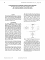
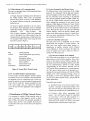
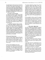
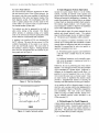
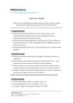
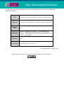
Provided by the author(s) and NUI Galway in accordance with publisher policies. Please cite the published
version when available.
Title
An Active-Node Fault Diagnosis System for CEBus Networks
Author(s)
Corcoran, Peter; Nolan, Paul J.; Humborg, Kenn; Lusted, Karl
Publication
Date
1995
Publication
Information
Lusted, K., Humborg, K., Nolan, P. J., & Corcoran, P. M.
(1995). "An active-node fault diagnosis system for CEBus
networks". "IEEE Transactions on Consumer Electronics", Vol.
41 (No. 3), pp. 884-889
Publisher
Item record
IEEE
http://hdl.handle.net/10379/275
Downloaded 2015-12-17T23:38:45Z
Some rights reserved. For more information, please see the item record link above.
884
IEEE Transactions on Consumer Electronics, Vol. 41, No. 3, AUGUST 1995
AN ACTIVE-NODE FAULT DIAGNOSIS SYSTEM FOR CEBUSNETWORKS
Karl Lusted,’ Kenn Humborg,’ Paul J. Nolan,2and Peter M. Corcoran’
’Dept. of Electronic Engineering, University College, Galway
2Dept. of Mechanical Engineering, University College, Galway
Abstract
The design and implementation of an active-node fault diagnosis system for CEBus networks is described. The system uses an
IBM PC with a user-friendly GUI to provide statistical information on network traflic and messages. The PC is linked to an
active CEBus node which monitors the network and can initiate
testing sequences controlled by the PC.
This consists of a CEBus node with a physical interface to the AC power-line [2]. This node is controlled
by a dedicated microcontroller with modified protocol
software to facilitate test and monitoring activities.
This ‘active-node’is linked to an IBM PC which controls the analysis of network monitoring activities and
presents data summaries and control functionality to
the system User via a GUI interface. The fault diagnosis system overview is given in Figure 1.
1. Introduction
The Consumer Electronic Bus (CEBus) is a multimedia LAN standard developed for home automation
applications [l]. The CEBus standard is a subset of
the OS1 seven-layer model. In particular it conforms
with the OS1 model at the three lower protocol levels:
physical, link and network layers [2]. The implementation of these lower layers is quite robust and a practical CEBus network is fault-tolerant with a low probability of communications errors propagating to the
higher layers. Despite this robustness, communications errors will still impact on network performance
generating increasing traffic, incomplete packets and
excessive usage of IACK call-backs [3]. In worst case
situations it is conceivable that a network may fail, or
be rendered dysfunctional, by a single faulty node.
Performance analysis and evaluations of the CEBus
[4,5] do not allow for badly-behaved nodes which can
have a noticeable effect on throughput and message
delay for the entire network.
In this paper we consider the design and implementation of a fault diagnosis system for practical CEBus
networks. The implementation described in this paper
is for the mains power-line medium, but can be
adapted for any of the media supported by the CEBus
standard.
We begin with a summary of packet communications
formats between the CEBus active-node and the PC,
followed by an outline of the principle types of
CEBus errors and how these can be detected. A description is then given of the fault diagnosis system.
Manuscript received June 12, 1995
0098 3063/95 $04.00
______________
r-Graphical User
Interface
Database
r-!
-
1
______ --+ Message Transfer Element
v
-
-.* Mod,/iedpmrocol\
7
-
A C Powerline
Figure 1. CEBus Fault Diagnosis System Overview
2. CEBus Packet and Data Formats
This section describes the communications interface
between the modified CEBus modem and the PC used
for the actual diagnosis of network fault conditions.
This is important for two reasons: firstly, some errordetection is carried out in the hardware implementing
the physical layer of the CEBus interface and this information can be trapped and passed on to the PC
software by the CEBus active-node and, secondly, the
packet formats described in this section provide our
second level of error-check on the transmission integrity of the CEBus network.
1995 IEEE
___
885
Lusted, et al.: An Active-Node Fault Diagnosis System for CEBus Networks
2.1 CEBus Modem to PC communications
There are two principle forms of data transmitted from
the modem to the PC:
(i) Single characters indicating errors detected by
the CEBus modem. These errors are generally
physical layer errors or errors in node operation,
e.g. packet collision on network, communications
buffer full, etc.
(ii) Received packets detected on the AC powerline medium. Received packets consist of standard
CEBus DLL frames received over the network encapsulated
with
Start-of-Packet
and
End-of-Packet characters. These extra characters
serve to distinguish the CEBus packets from the
character-based communication of detected errors.
The standard CEBus frame format using SE error
detection is given in Figure 2.
PRE Control DA D H C SA S H C
PRE :
Control :
DA :
DHC :
SA :
SHC :
Information :
Information
Packet preamble
Control field (packet type, priority,
service class)
Destination Address
Destination House Code
Source Address
Source House Code
Information field
Figure 2: Normal MAC Frame Format
2.2 PC to CEBus Modem Communications
In active mode, the fault diagnosis system transmits
test packets over the AC powerline. These test packets
are designed to test for a particular type of error suggested by analysis of received packets during passive
mode. The PC sends DLL frames preceded by a Network Layer header, and any requests for Network
Layer services from the Application Layer (diagnosis
system).
3 Classification of CEBus Network Errors
It is necessary to classify CEBus network errors in
order to develop a fault diagnosis system to detect
them. CEBus errors have been grouped according to
protocol layer, the list is not complete, but does give
an indication of the type of errors that can be expected
to occur.
3.1 Errors Generated in the Physical Layer
The Physical Layer is the lowest layer of the CEBus
protocols. It is concerned with the physical transmission and reception of bits on the CEBus medium, i.e.
the AC powerline. Errors occurring in the physical
layer are not normally reported to higher CEBus layers, but the CEBus modem software has been modified to indicate the occurrence of such errors for the
purposes of fault diagnosis. Elements of Layer System
Management [2J techniques are used to pass information from the lower protocol layers to the Application
Layer. Physical layer errors are useful for collecting
network statistics, which can provide valuable information to the failure analysis software. Typical Physical Layer errors include packet collisions, loss of carrier, transmission aborted, etc.
3.2 Errors in the Data Link Layer
The Data Link Layer is responsible for the correct
transmission and reception of CEBus packets. The
Data Link Layer handles acknowledge packets, retransmission of packets, ensuring correct Channel
Access Method, etc. Errors occurring in the Data Link
Layer are usually not as easy to detect as errors occurring in the Physical Layer.
3.2.1. Incorrect Channel Access Method
All CEBus nodes must adhere to a set of rules for obtaining access to the Powerline medium. These rules,
known as the Channel Access Method, stipulate certain delay times before attempting channel access after
the last communication, deferral to nodes already
communicating on the network, allowing time for
ACK packets before attempting new communications,
etc. Thus, most of these errors can be detected by examining the inter-packet timings sent from the CEBus
Modem to PC. These inter-packet timings consist of
the number of USTs (Unit Standard Times) elapsed
since the last CEBus channel activity, and precede the
packet information.
Detectable errors include:
(i) Insufficient delay time between packet transmissions. Generally, if inter-packet timing is less
than I O USTs then the communicating node is not
waiting long enough between communications [3].
(ii) Excessive delay before transmitting ACK
packet. Any ACK packet should be transmitted
not more than 6 USTs [3] after reception of a
packet requiring an acknowledgement. This is to
ensure that ACK packets are always sent before
standard packet communications begin again.
886
IEEE Transactions on Consumer Electronics, Vol. 41, No. 3, AUGUST 1995
The fault diagnosis system must not only examine the
inter-packet timing, but also the packet type to see if
the Channel Access Method is being adhered to. The
Channel Access Method also specifies additional delays for packet priority, packet queuing, and randomisation. By examining the inter-packet timings and the
packet data containing priority information, etc., the
fault diagnosis system can detect more subtle errors in
the Channel Access Method.
3.2.2. Failure to send ACK packet
If a CEBus node transmits a packet and the packet
data indicates that an ACK packet is expected, then
the next packet received should be an ACK packet
from the receiving node. The fault diagnosis software
must examine all packets to see if an ACK packet is
requested, and then check the next packet to see if an
ACK packet was sent. Failure to do so suggests that
the receiving node is faulty and can be checked in
active mode by the transmission of packets to the suspected faulty node.
3.2.3. Multiple transmission of the same packet
If a CEBus node continually transmits the same
packet to another CEBus node even though the original packet was received correctly, the transmitting
node may be faulty. This error can only be detected by
creating a database of all original packets on the
CEBus network during the passive mode analysis. A
new packet is added to this database only if it can not
be found in the database already. Each time a match is
found for a particular packet, a counter for that packet
is incremented. Thus the excessive transmission of a
particular packet can be detected.
3.3 Errors in the Network Layer
The Network layer is primarily concerned with packet
routing in a CEBus network which may consist of
several different media linked through a series of
Routers and Brouters. The fault diagnosis system outlined in this paper deals with errors on a single me-dium but may be extended to detect errors in the
Network layer.
3.4 Errors in the Application Layer (CAL)
Error detection in the Application Layer has not been
implemented in the current version of the fault diagnosis software. This is principally because of the potential complexity of CAL constructs. However some
preliminary studies have been undertaken and the
framework of an interpretation and diagnosis system
for CAL is described briefly.
The Common Application Language (CAL) provides
a framework through which CEBus devices may
communicate with, and control objects on another
CEBus device [ 6 ] . The CAL uses a particular syntax
whereby every object on a CEBus device has a set of
properties associated with it, known as Instance Variables (IVs). The values of these IVs completely define
the object in question and they may be read only or
readwrite. All CEBus devices can be represented by a
collection of such Objects. Mistakes and errors in the
CAL syntax of CEBus packets can be detected by a
system which relies on a set of grammatical rules for
CAL.
It is also possible for devices to send CAL messages
that refer to objects on a device that do not exist, refer
to IVs within an object which do not exist, etc. The
standard specifies that each node can be asked to
supply details of its constituent objects. The system
can thus build up an internal representation of the
devices of the network [7]. The validity of CAL messages can be checked by using this information in the
analysis stage.
4. The Active CEBus Node
The “active” CEBus-node is controlled by a dedicated
microcontroller with modified protocol software to
facilitate test and monitoring activities. The Medium
Access Control (MAC) sublayer of the data link layer
has been modified to allow the system to receive and
record all network packets. These captured packets are
passed to the Application layer along with channel
timings in Unit System Times (USTs). Network errors
detectable by the lower layers of software in the
CEBus node are also passed to the Application layer
for storage to an integrated database.
4.1 Active Node Hardware
This consists of three main functional subsystems:
interface circuitry to the mains powerline; a spreadspectrum mains modem IC and a supervisory microcontroller.
A small CEBus network was implemented using five
CEBus mains modems. Three of the modems can be
operated in standalone mode. In this mode, packet
sequences can be programmed to repeat periodically
and random packet generation is also supported.
The remaining two nodes were connected to IBMcompatible PCs and controlled by software running on
the PCs. One node was used to implement the fault
diagnosis system. The other node was used to simulate faults by transmitting invalid packets and disobeying the channel access protocols.
887
Lusted, et al.: An Active-Node Fault Diagnosis System for CEBus Networks
4.2 Active Node Software
The microcontroller subsystem implements the datalink and network layers of the CEBus protocols. For
the present work they were modified to facilitate the
requirements of the 'active' and 'passive' modes of the
fault diagnosis system. The modifications allow the
node to capture packets from all other nodes on the
system when it is in passive mode. In active mode it
can simulate another system node.
Test packets can also be generated by the node to
allow active testing of the network. This feature
allows periodic or continuous testing of a suspect
node on the network and would be particularly useful
for the detection of intermittent fault conditions.
A graphical user interface (GUI) was developed for
the PC software. This gives the user access to all the
available functionality of the system in an easy-tolearn and user-friendly manner. The main screen of
this interface is shown in Figure 3. Plotting functions
have also been incorporated into the software to produce graphs such as Figure 4.
5. Fault Diagnosis System Operation
Initially the system simply 'listens in' on the CEBus
network, recording all network events (packets and
physical layer errors and signals) and their associated
timings and storing this information to a database. The
system then analyses the collected data in an attempt
to detect faults or determine probable fault scenarios.
The analysis engine produces a set of packet sequences designed to confirm or disprove its hypotheses
and to collect additional data if required.
After the analysis stage, the system transmits the test
packets and records network events. The analysis
stage is performed again to give an improved diagnosis. The process can be repeated as often as desired.
The test sequences of packets transmitted over the
network are re-configurable and extendible as further
network faults are categorised and their test conditions
identified. At present data for active test packet sequences is generated in two ways:
(i) Pre-defined packet sequences can be defined in
a data file which is loaded when the PC software
starts up.
(ii) Additional sequences can be manually generated while the program is running and saved to a
data file for future use.
Effectively, the user is performing part of the analysis
function. It is envisaged, however, that the procedure
will be automated to a greater degree. Improved intelligence in the diagnosis engine would allow it to
generate its own test sequences from a set of primitives in much the same way as a human would. Using
an expert system to implement the analysis engine
provides a straightforward method of encoding the
necessary rules and heuristics for this type of analysis.
Figure 3: The User Interface.
As our studies are still at a formative stage it is not yet
clear how such a system could be best implemented to
provide a practical balance of flexibility, transparency
and extendibility. This must await more detailed
studies on a range of CEBus networks, ideally covering the different physical media described in the
CEBus standard [ 2 ] .
ChannelAdvm/lrom 28/05/9521 4023l026/05/95 21 45 15
6T
/
1
0 AA:
n :Mnd c
Errors
d
6. Methodologies for Fault Diagnosis
~
Figure 4: Graph of network activity
A basic analysis engine was developed using a readily
available expert system. In general expert systems are
classified as either data driven (pattern directed) or
goal driven. The particular expert system used in this
project is pattern driven in that it comprises:
0
working memory
888
IEEE Transactions on Consumer Electronics, Vol. 41, No. 3, AUGUST 1995
production memory (rules)
an inference engine
The expert system thus works by trying out rules
(based on the current state of the working memory)
using the inference engine and updating the working
memory as rules are fired. This approach is most suitable for general monitoring and analysis of the CEBus
traffic. In particular it is expected to be particularly
appropriate in analysing the application layer, where
there will be a very large number possible solutions
involving various objects, instance variables ( W s )
and CAL language constructs. The alternative approach (diagnosis or backward search approach) can
also be readily implemented. In this case the goal is
placed in working memory and matched against the
"actions" of the production rules. This strategy is generally more suitable for diagnosis applications where
there is a small number of possible outcomes. The
generality of system in implementing both forward
and backward search (or a combination of both) and
well as the ease with which heuristics can be included
are important at this stage of development of the project.
The data collected by the system is converted into a
form suitable for input into the expert system. Each
event is represented as a Working Memory Element
( W E ) . A sample of the WME file is shown in
Figure 5. Each WME comprises a unique identifier
for the event and various attributes of the event (such
as time, event type, packet contents, etc.).
(rec "no 570 "date 28-05-95 "time 21-43-00 "source 0 "destin 0 "ust-del 0
priate CAL instructions are added to the rule base.
The inclusion of heuristics information and the intelligent application of the active mode also requires the
expert system.
The diagnosis implemented to date has used rules
explicitly specified by engineering knowledge of the
CEBus protocol and the likely faults. An alternative
approach which may be necessary is to use rule induction from a large example set. This will be used to
complement the rules deduced above.
7. Conclusions
A working CEBus fault diagnosis system for the AC
powerline medium has been developed. The system
has been designed to monitor network traffic and perform a range of analyses for actual and incipient fault
conditions. It provides a useful aid to the developers
of CEBus devices and has the potential to be applied
as a practical tool in the debugging of faulty CEBus
networks.
REFERENCES
[I] Hofmann, J., "The Consumer Electronic Bus: An Integrated Multi-Media LAN for the Home", International
Journal of Digital and Analog Communication Systems, Vol. 4, No. 2, Apr. 199 I , pp. 77-86, 199 1.
[2] EIA Home Automation System (CEBus) Interim Standard IS-60. Vol. 1 , Parts 1,7.8, EIA, June 29, 1992.
[3] EIA Home Automation System (CEBus) Interim Standard IS-60, Vol. 4, EIA, June 29, 1992.
"mess P "type 00 "prev 569 "plist empty )
(rec "no 571 "date 28-05-95 "time 21-43-02 "source 3 "destin 2 "ust-del 0
"mess P "type 09 "prev 570 "plist 70 E7 OF F4 30 34 F5 FF FF FF FF )
(rec "no 572 ^date 28-05-95 "time 21-43-02 "source 0 "destin 0 "ust-del 0
"mess P "type 00 "prev 571 "plist empty )
Figure 5: Sample data with WME elements.
Rules in the expert system comprise one or more
condition elements (CEs) and actions. The CE's are
the IF part of the rule and the actions are the THEN
parts. The syntax is quite straightforward and is described in [8].
It should be strongly emphasised that the results presented so far could have been implemented algorithmically e.g. using a BASIC, C program or using
the search facility in an available data base. The
power of an expert system becomes clear when the
rules for the underlying CEBus objects and the appro-
[4] Pakkam, S.R. and Manikopoulos, C.N., "Performance
Evaluation of the Consumer Electronic Bus", IEEE
Trans. Consumer Electronics, Vol. 36. Nov. 1990. pp.
949-953.
[ 5 ] Yang, J. and Manikopoulos, C.N. "Performance Comparisons of the CEBus with other Protocols" IEEE
Trans. Consumer Electronics, Vol. 39, Nov. 1993. pp.
824-83 1.
[6] EIA Home Automation System (CEBus) Interim Standard IS-60, Vol. 8. EIA. June 29. 1992.
[7] Corcoran, P.M. and Lusted, K. "A Remote Electronic
Object Emulation System for Home Bus Applications".
IEEE Trans. Consumer Electronics, Vol. 40, Aug. 1994.
pp. 405-410.
[SI Forgy. C. L., OPS5 User's Manual, Technical Report
CMU-CS-81-135, Department of Computer Science.
Carnegie-Mellon University.
Lusted, et al.: An Active-Node Fault Diagnosis System for CEBus Networks
889
Biographies
Peter Corcoran received the BA1 (Electronic Engineering) and BA (Maths) degrees from Trinity College Dublin in 1984. He continued his studies at TCD
and was awarded a Ph.D. in Electronic Engineering in
1987 for research work in the field of Dielectric Liquids. In 1986 he was appointed to a lectureship in
Electronic Engineering at UCG. His research interests
include microprocessor applications, environmental
monitoring technologies, and automated testing of
electronic components and equipment. He is a member of the IEEE.
Paul J. Nolan is a Statutory Lecturer in Mechanical
Engineering at University College, Galway. He received the BE degree from University College Dublin
and the M.Eng and PhD degrees in electrical
engineering from McMaster University in Ontario.
His employment included work at Power Technologies Inc (Schenectady, NY). His research interests
include computer simulation and control and application of AI in engineering.
Karl Lusted received his BE degree in Electronics
from University College Galway in 1992. He is presently studying for the degree of M.Eng.Sc at UCG.
His research interests include microcontroller applications and communications network protocols. He is a
member of I.E.I. and an associate member of I.E.E.
Kenn Humborg received the BE degree in Electronic
Engineering from University College, Galway in
1994. He is presently studying for an M.Eng.Sc degree at UCG. His research interests include computer
networking and application of fault diagnosis methods
in automatic test equipment.