1
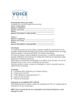
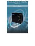
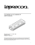
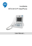
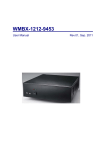
TM
InfoWave
User's Guide
Model 9209/9211/9213/24211/24213
Model 9210/9212/9214/24212/24214
Version 1.1
InnoMedia Inc.
90 Rio Robles
Suite 100
San Jose, CA. 95134
The InnoMedia Wireless Group
http://www.innomedia.com/wireless/
1
Preface
Disclaimer
The information in this document is preliminary and subject to change without notice.
InnoMedia reserves the right to change any portion of this product for reasons such as
improving performance or enhancing functionality. InnoMedia assumes no liability
arising out of the application or use of this product for anything other than its intended
purpose.
Copyright
This document is copyrighted material. No part of this document may be copied by any
means without the written permission of InnoMedia Inc.
InfoWave User Guide (Model 9209/9211/9213/24211/24213 and Model
9210/9212/9214/24212/24214), First Edition (November 1999)
This document describes the InfoWave system from InnoMedia Inc. This document is the
official reference source for all revisions/releases of this product until rescinded by an
update.
Copyright © 1997, 1998, 1999 by InnoMedia Incorporated. All rights reserved.
FCC Certification
This device has been tested and complies with Part 15 of FCC rules. Operation is subject
to two conditions: (1) This device may not cause harmful interference. (2) This device
must accept any interference received including interference that may cause undesirable
operations. If this device causes or receives interference from other equipment, the user
can reorient the device’s antenna or move the device to a different location.
Modifications to this device without the manufacturer’s approval could void the user’s
authority to operate this device.
Trademark Acknowledgment
The InnoMedia logo design is a registered trademark of InnoMedia PTE Ltd. All other
brand and product names may be trademarks of their respective companies.
The InnoMedia Wireless Group
http://www.innomedia.com/wireless/
2
Customer Support
United States:
Customer Service: 408-432-5400
Technical Support: 408-432-5442
Singapore:
Customer Service: 65-872-0828
Technical Support: 65-872-0828
Taiwan:
Customer Service: 886-3-564-1299
Technical Support: 886-3-564-1299
For troubleshooting tips and frequently asked questions, visit our Web site at:
http://www.innomedia..com/wireless/
The InnoMedia Wireless Group
The InnoMedia Wireless Group offers wireless products ranging from OEM components
to complete end-user products. With expertise in radio design, baseband signal
processing, firmware, device drivers, spread-spectrum technology, and communications
system design, the InnoMedia Wireless Group is dedicated to working with its OEM
customers and business partners to help them develop innovative wireless products.
The InfoWave product family consists of InfoWave and OEM transceiver, transmitter,
and receiver modules. All members of the InfoWave families use direct-sequence
spread-spectrum (DSSS) technology and, depending on country-specific regulations, can
be customized to operate in either 902-928 MHz or 2.4-2.483 GHz bands.
The InfoWave unit has been certified by FCC and Industry Canada. For users who prefer
to directly control the transceiver, transmitter, or receiver, InfoWave OEM modules can
be customized to meet their requirements. InfoWave technology has been used to support
wireless data collection, home security systems, and the control of such devices as mobile
robots, surveillance cameras, studio lighting systems, and electronic white boards.
Points of Contacts:
OEM Business Development: [email protected]
OEM Business Development: [email protected]
The InnoMedia Wireless Group
http://www.innomedia.com/wireless/
3
Table of Contents
Preface................................................................................................................................ 2
Disclaimer........................................................................................................................ 2
Copyright ......................................................................................................................... 2
FCC Certification ............................................................................................................ 2
Trademark Acknowledgment .......................................................................................... 2
Customer Support ............................................................................................................ 3
The InnoMedia Wireless Group ...................................................................................... 3
Introducing InfoWave ...................................................................................................... 5
What is InfoWave? .......................................................................................................... 5
PC to PC Networking (Model: 9209/9211/9213/24211/24213)...................................... 5
PC to Peripheral Connection (Model: 9210/9212/9214/24212/24214)........................... 5
PC to Multiple Devices Communication (Model: 9208/9218/9228/24218/24228) ........ 5
Hardware Installation ...................................................................................................... 6
InfoWave Hardware ........................................................................................................ 7
InfoWave Model 9209/9211/9213/24211/24213 ............................................................ 8
InfoWave Model 9210/9212/9214/24212/24214 ............................................................ 8
Installing the Hardware ................................................................................................... 9
Using the Power Adapter Cables..................................................................................... 9
Changing the InfoWave Baud Rate ............................................................................... 10
Synchronize Your InfoWave Units ............................................................................... 10
Configuring Your Computer's Serial Port ................................................................... 12
Changing Your Cable Wiring to Bypass InfoWave Hardware Flow Control ............... 13
The InnoMedia Wireless Group
http://www.innomedia.com/wireless/
4
Introducing InfoWave
Congratulations on purchasing InfoWave! You have made the right decision to bring the
power of wireless technology into your hands, and you will soon discover the many
delightful advantages and the wonderful benefits made possible through the magic of
wireless connectivity.
This chapter will introduce you to InfoWave and describe some of the advantages and
possible uses of your new product.
What is InfoWave?
InfoWave is a low-cost solution for such applications as cable replacement, wireless
home networking, and remote data collection and control. Using the digital spreadspectrum technology, InfoWave is a plug-and-play RS-232 cable replacement -- just
connect it to a serial port and it provides transparent wireless connectivity. InfoWave
offers reliable and secure communications between computers or data devices at
distances of up to 350 feet indoors and 1000 feet outdoors.
PC to PC Networking (Model: 9209/9211/9213/24211/24213)
By simply connecting an InfoWave unit to each computer's serial port, the two InfoWave
units establish a point-to-point connection between two computers. You can download
and install the InfoWave Networking Software from InnoMedia's web site or use other
software applications such as Hyper Terminal and pcANYWHERETM.
The InfoWave Networking Software turns two computers into a mini-network. Now,
the peripherals and files of the two computers can allows two users to print with the same
printer, fax or email with same modem, exchange files, and play games with each other.
Moreover, both users can simultaneously and independently surf the Web using the same
phone line and the same Internet Service Provider account. Users can download the
InfoWave Networking software from our Web site http://www.innomedia.com/wireless/.
PC to Peripheral Connection (Model: 9210/9212/9214/24212/24214)
Two InfoWave units can provide a point-to-point communication between a PC and a
data communication device like an external V.90 modem without any software
installation.
PC to Multiple Devices Communication (9208/9218/9228/24218/24228)
For point-to-multipoint applications, one InfoWave unit can serve as a base station to poll
many remote stations. For example, one computer can control multiple mobile robots by
using the InfoWave units. Using a simple InfoWave command set, users can easily
integrate the InfoWave into their remote data collection and control applications.
The InnoMedia Wireless Group
http://www.innomedia.com/wireless/
5
Hardware Installation
InfoWave can be installed in just minutes. This chapter discusses the hardware
installation of the InfoWave system, including a description of the InfoWave hardware
components and an installation procedure.
The InfoWave kit (Model 9209/9211/9213/24211/24213/9210/9212/9214/24212/24214)
consists of:
1.
2.
3.
4.
5.
6.
7.
8.
2 InfoWave units,
2 Power adapters,
1 mini-Din PS/2 power cable,
1 Din power cable,
2 9-pin-to-9-pin RS-232 cables,
2 9-pin-to-25-pin adapters,
1 User's manual, and
1 one-year warranty card.
The illustration below shows a general diagram of how the two computers are set up with
InfoWave units.
Model 9209/9211/9213/24211/24213
The InnoMedia Wireless Group
Model 9210/9212/9214/24212/24214
http://www.innomedia.com/wireless/
6
InfoWave Hardware
The following figure and table describe the InfoWave hardware.
Reference
1
Function
Power Indicator
2
DCD Indicator
3
DTE Indicator
4
Antenna
5
Power Switch
6
DTE-DCE Switch
7
DC Power Input
8
9-pin Serial Port
9
25-pin Parallel Port
(Optional)
The InnoMedia Wireless Group
Description
Indicates power is on when lit.
Flashes when in Sync mode.
Indicates unit is connected when lit. Light
blinks when transferring data and turns off
after 30 seconds of inactivity.
Set unit to DCE mode for connecting to a
computer and the indicator is off. When it
turns on, the unit is set to Sync mode. In Sync
mode, two InfoWave units synchronize their
PN codes.
Transmits/Receives signal to/from another
unit.
Press into the lock position to turn on the unit.
Press again to turn off the unit.
Slide to the left for synchronization, and to the
right for normal data communication.
+5V DC power input. Positive polarity is at
the center.
Female 9-pin connector for serial connection
to a PC or serial communication device.
Reserved for OEM use
http://www.innomedia.com/wireless/
7
InfoWave Model 9209/9211/9213/24211/24213
The DTE-DCE switch should be set to the right position as shown below and the DTE
indicator should be off. If the switch is set to DTE (left) position, the unit is in the
synchronization mode and the PWR indicator will be flashing. Please refer to the
synchronization section.
Unit 1 to Computer
PWR
DCD
DTE
Unit 2 to Computer
PWR
DCD
OFF
DTE
OFF
InfoWave Model 9210/9212/9214/24212/24214
One unit is set to the DCE mode and the other unit is set to the DTE mode as illustrated
below. If the switch is set to the opposite position, the unit is in the synchronization
mode, and the PWR will be flashing. Please refer to the synchronization section.
Unit 1 to Computer
PWR
DCD
DTE
OFF
The InnoMedia Wireless Group
Unit 2 to Peripheral
PWR
DCD
DTE
ON
http://www.innomedia.com/wireless/
8
Installing the Hardware
The steps below show you how to connect an InfoWave unit to a computer.
1. Power off the computer.
2. Take one serial cable out of the InfoWave kit. Connect one end of the serial cable to
the 9-pin male communications (COM) port on your computer. If your computer has
a 25-pin COM port, use the 9-to-25-pin adapter included in the package.
3. Connect the other end of the serial port to the 9-pin female COM port on the back of
the InfoWave unit.
4. Plug the power supply pack into the +5V DC power input in the back of your
InfoWave unit.
Hardware installation is now completed on one computer. Remember to perform the
entire procedure for the other computer to be networked. The following picture shows the
detailed information about how to complete the hardware installation.
Using the Power Adapter Cables
One PS/2 power adapter cable is included in the InfoWave kit. The power adapter cable
allows you to power up the InfoWave unit from a desktop or notebook PC instead of
using the AC/DC power adapter. To use the cable, do the following:
1. Connect one end to the InfoWave DC power supply, and connect the other end of the
cable to a PS/2 pass-through connector.
The InnoMedia Wireless Group
http://www.innomedia.com/wireless/
9
2. Remove either the PS/2 mouse or keyboard connector first, then plug in the PS/2
pass-through connector. Finally, plug in the PS/2 mouse or keyboard connector on top
of the PS/2 pass-through connector.
Changing the InfoWave Baud Rate
The default baud rate of the InfoWave is 115.2 Kbps. A user can change the baud by
doing the following steps. However, please notice that you only can change the baud of
DCE mode InfoWave by issuing commands. For DTE mode InfoWave, please contact
our technical support to get a different firmware you needed.
1. Power on the InfoWave unit and connect it to one of the RS-232 ports.
2. Use the Microsoft Hyper Terminal application by doing
Start à Programs à Accessories à Communications à Hyper Terminal
3. Enter an escape sequence "|||" <CR> and a WMBx <CR>, where <CR> is the
"Carriage Return" or "Enter". You need to consecutively and quickly enter the three
"|" and then hit the <CR>. The timing between the keystrokes should be less than 0.5
second. After seeing the InfoWave respond with an "0" or "OK", you can then type in
the WMBx to set the baud rate,
Where
x = 1 for 115.2 Kbps,
x = 2 for 57.6 Kbps,
x = 3 for 38.4 Kbps,
x = 4 for 19.2 Kbps,
x = 5 for 9.6 Kbps.
4. Power off the unit and then power it back on.
5. Repeat the step 1 to 4 for the second InfoWave unit.
Synchronize Your InfoWave Units
If two InfoWave units are configured for replacing an RS-232 cable, the unique
identification code of this pair is pre-set during the manufacturing process. A
synchronization step is needed when two units fail to connect to each other due to a new
firmware upgrade or another pair of InfoWave operating in the close proximity.
The synchronization steps are:
1.) Turn off the power of each unit by pressing the power switch.
The InnoMedia Wireless Group
http://www.innomedia.com/wireless/
10
2.) If it is a DCE InfoWave unit, which connects to a computer, slide the switch
to DTE side, and if it is a DTE InfoWave unit, which connects to a modem,
slide the switch to DCE side. Please note that you need to unplug the RS-232
cable during the synchronization procedures.
3.) Turn on the power of each InfoWave unit by pressing the power switch again.
4.) After each unit's PWR LED has slowly blinked 3 times and then begun to
flash faster, slide the switch back to the original position.
5.) The PWR LED will now slowly blink 3 times and then light up solid.
After these steps are completed, the two InfoWave units should be able to operate
flawlessly. If you still encounter any difficulties, please contact InnoMedia's technical
support.
The InnoMedia Wireless Group
http://www.innomedia.com/wireless/
11
Configuring Your Computer's Serial Port
InfoWave uses hardware flow control to ensure reliable data transmission. Your PC
COM port needs to be configured as shown below. To configure the serial port, do the
following:
1. At Windows 95 and 98 desktop area, issue the command sequences:
Start àSettings à Control Panel à System à Device Manager à Ports à COM1
or COM2
All the parameters should be set as shown in the above figure except the "Bits per second
" box. Choose the correct baud rate that matches your InfoWave setting.
The InnoMedia Wireless Group
http://www.innomedia.com/wireless/
12
Changing Your Cable Wiring to Bypass InfoWave Hardware Flow Control
For a device does not support hardware flow control, special cable wiring is needed to
bypass the hardware flow control. Pin 4, 6, and 7 of the InfoWave female connector need
to be connected together. The following figure and table show the female connector
layout and pin assignment respectively. Note that once the hardware flow control is
disabled, the user needs to exercise caution to prevent data overrun that can result in loss
of data packets.
1
6
Female Connector
of
InfoWave Unit
9
5
Pin No. Pin Name
I/O
(DCE)
I/O Comments
(DTE)
1
/DCD
O
I
2
3
4
RXD
TXD
/DTR
O
I
I
I
O
O
5
6
7
8
9
GND
DSR
/RTS
/CTS
/RI
O
I
O
O
I
O
I
I
In DCE mode, when the radio link is established,
DCD is asserted. When the link is torn down,
DCD becomes de-asserted.
In DCE mode, DTR must be asserted before data
can be sent out normally.
Hardware flow control signal.
Hardware flow control signal.
For device that does not support hardware flow control, Pin 4, 6, and 7 of the InfoWave
female connector need to be connected together.
The InnoMedia Wireless Group
http://www.innomedia.com/wireless/
13