1
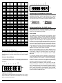
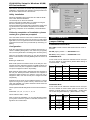
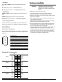
Introduction
The PCM-3614 is a PC/104-compatible module with four individually configurable RS-422/485 ports. It works with PC/
104 CPU modules to extend additional RS-422/485 ports. The
PCM-3614 also features lots of functions such as high transmission speed 921.6 kbps, independent/shared IRQ and more.
It also provides high-performance 16C550 UART communication chip with 16-byte FIFO to reduce CPU load. This makes
the PCM-3614 especially suitable for multitasking environments.
• IRQ: 3, 4, 5, 6, 7, 9, 10, 11, 12, 15
• Data bits: 5, 6, 7, 8
• Stop bits: 1, 1.5, 2
• Parity: none, even, odd
• Speed (bps): 50 ~ 921.6K
• Connectors: Four DB-9 male
• Signal support: TxD+, TxD-, RxD-, CTS+, CTS-,
RTS+ and RTS-
The PCM-3614 comes with a Windows 95/98/NT/ME configuration utility (Windows 2000/XP utility will soon be ready
and allowed to download through our Web site). The Windows configuration utility provides functions such as self-diagnostics and performance analysis for easy troubleshooting
and debugging.
• Surge protection: 1000 VDC
The PCM-3614 provides versatile function settings to meet
users' needs. These function settings include Standard/Enhance mode, Independent/Shared IRQ mode and Speed
mode. Standard/Enhance mode setting helps the user use
base address more flexible. Especially in Enhance mode, different base addresses can be set according to the application. In Shared IRQ mode, all ports of interrupt can be specified to one. This solves the problem of IRQ insufficiency within
the embedded system. In Speed mode, the PCM-3614 allows transmission rate up to 921.6 kbps, improving the overall performance of the system.
Humidity, non-condensing
Features
• Four Independent RS-422/485 serial ports
• Automatic RS-485 data flow control
• Transmission speeds up to 921.6 Kbps
• Shared IRQ settings for each port
• Windows configuration utility for Windows 95/98/NT/ME
P.S. Windows 2000/XP/CE driver will soon be available on
our Web site
• Temperature:Operating : 0 ~ 65° C
(refer to IEC-68-1-1,2) ( 32~149° F)
Storage : -25 ~ 80° C (-13~176° F)
• Operation Humidity: 0% ~ 90% Relative
Product Package
• PCM-3614 PC/104 4-port RS-422/485 HighSpeed Module
• Advantech ICOM Driver/Utility CD
• One cable
Initial inspection
We carefully inspected the PCM-3614 both mechanically and electrically before we shipped it. It should
be free of marks and scratches and in perfect electrical order on receipt.
Handle the board only by its edges. The static change
on your body may damage its integrated circuits.
Keep the card in its anti-static package whenever it
is not installed. You can use this package to return
the card if it should need repair.
PCM-3614 4-port RS-422/485 High-Speed Module
PCM-3614
4-port RS-422/485 High-Speed Module
Board Layout
• Built-in termination resistors
• LED indicators: TX, RX
• Standard PC ports: COM1, COM2, COM3, COM4
compatible
Specification
• Bus interface: PC/104 (ISA)
• Number of ports: 4
• I/O address: 0x000 ~ 0x3F8
• UART: 4 x 16C550
PCM-3614 User's Manual
PC/104 and the PC/104 logo are trademarks of the PC/104 Consortium
Part no. 2000364100 1st Edition
1
Printed in Taiwan August 2000
In standard mode, the I/O address of the ports are as follows:
Interrupt No.
Selectable
Selectable
Selectable
Selectable
M1
A9
A8
M0
Enhanced mode
A7
The board is shipped with default settings. If you need to
change these settings, however, see the following sections.
Otherwise, you can simply install the card.
I/O address
3F8
2F8
3E8
2E8
1
2
3
4
A6
Default Settings
Port
Port
Port
Port
Port
A5
Each port on the PCM-3614 card requires configuration prior
to use. The DIP switches set ports to the appropriate I/O address (SW2) and different modes (SW1). The jumpers set the
port's IRQ.
A4
Card Configuration
ON
PCM-3614 Default Configuration
Setting
Default Function
JP3
IRQ 5
Speed Mode
1x
IRQ mode
Share
Base Address
Address 300H
Vector Address
Interrupt 280H
Standard/ Enhanced Enhance
Operating System
Windows 95/98/NT
SW1
In enhanced mode, you can select a different base address.
The base address determines the address for each of the
four ports.
The I/O addresses for the four ports are as follows:
Jumper and switch settings
The PCM-3614 can function in many different modes according to your application needs. These modes include Standard/
Enhanced Mode, Independent/Shared IRQ Mode, Speed
Mode, and Operating System Mode. Details of these specific
modes are described as follows:
Port
Port
Port
Port
Port
I/O address
Base + 00H
Base + 08H
Base + 10H
Base + 18H
1
2
3
4
You use switches 1~7 of DIP switch SW2 to set the base
address anywhere from hex 200 to 3F8.
To set the base address, you have to calculate the base
address as follows: (switch ON is “0”, switch OFF is “1”.)
Standard/Enhanced Mode (M0)
PCM-3614 can be used in standard or enhanced mode. In
standard mode the I/O addresses are compatible with the
standard PC communication ports, COM1 ~ COM4. In enhanced mode you can select a different base address. The
offset of each port from the base address is fixed. You can
use M0 of DIP switch (SW1) to select standard or enhanced
mode.
HEX
value
A3
A4
A5
A6
A7
A8
A9
8
10
20
40
80
100
200
8
16
32
64
128
256
512
SPEED
A9
A8
A7
A6
A5
A3
Switch is set ON.
A4
In the following sections, we will use the icons shown below
to represent switches set for ON or OFF.
Base address Decimal
line
value
ON
Switch is set OFF.
The following table shows different base address settings.
Port base address (SW2)
Base Address
A3 A4
200 - 207 (hex)
l l
M1
M0
A9
A8
A7
A6
A5
A4
Standard mode
SW1
A6
A7
A8
A9
l
l
l
l
l
l
¡
¡
l
¡
¡
l
¡
¡
¡
¡
¡
¡
¡
¡
¡
l
*300 - 307 (hex) l
l
l
¡
l
¡
¡
208 - 20F (hex)
ON
A5
l
l
3E8 - 3EF (hex)
3F8 - 3FF (hex)
l: ON
¡
¡
¡: OFF
* : Default
Note: If your CPU module or card has serial interface ports,
you will need to adjust the I/O port addresses (or disable the ports) to avoid conflicts.
2
PCM-3614 User's Manual
M1
M0
A9
A8
A7
A6
A5
A4
Independent/Shared IRQ mode
(M1, JP3, JP4, JP6, JP7)
ON
The card’s IRQ can be set using M1 of SW1. Please note that
the DIP switch is for setting the mode as shown below.
SW1
M1
M0
A9
A8
A7
A6
A5
A4
Shared IRQ Mode
ON
SW1
M1
M0
A9
A8
A7
A6
A5
A4
Independent IRQ Mode
Interrupt Status Register SW1
Bit
Function
0
Port 1
1
Port 2
2
Port 3
3
Port 4
4
Not Used
5
Not Used
6
Not Used
7
Not Used
ON
SW1
Independent IRQ (JP1-JP4)
In this mode, each of the four ports can have IRQ channels
set individually. For each port, select an IRQ not in use by
other devices in the system. The map of jumpers and ports is
shown below.
Port 1 —> JP3
Port 2 —> JP4
Port 3 —> JP5
Port 4 —> JP6
Shared IRQ (JP3)
Select an IRQ which is not in use by another card in the system. If you are installing more than one PCM-3614, set them
to different IRQ numbers. Jumper Bank JP3 controls the card
IRQ. Please refer to the following figure for example.
3
4
5
6
7
9 10 11 12 15
JP3
Interrupt Status Register Setup (SW1, Vector
address)
The feature on the PCM-3614 is utilized in the shared IRQ
mode. When data arrives at any one of the four ports, an interrupt will be generated in the interrupt register. The PC software can read this, and identify immediately which port generated the interrupt. This saves time and makes programming
easier. When a data bit of the interrupt status register is set to
0, the corresponding channel is selected to generate an interrupt. If the bit is 1, then no interrupt is generated. The DIP
switch, SW1, controls the card’s interrupt status register, as
shown in the following figure and table.
PCM-3614 User's Manual
The user may change the interrupt status address via SW1.
Please note that the address decoder will occupy a continuous, 16-byte area, according to the switch setting. For example, if you set the switch to 210H, then the address 210H to
21FH will be decoded. The various DIP switch settings (SW1)
for the interrupt status register are shown in the table below.
A4
A5
A6
A7
A8
A9
Interrupt
Register
ON
ON
ON
ON
ON
ON
000H
OFF
ON
ON
ON
ON
ON
010H
ON
OFF
ON
ON
ON
ON
020H
OFF
OFF
ON
ON
ON
ON
030H
ON
ON
OFF
ON
ON
ON
040H
OFF
ON
OFF
ON
ON
ON
050H
ON
OFF
OFF
ON
ON
ON
060H
OFF
OFF
OFF
ON
ON
ON
070H
ON
ON
ON
OFF
ON
ON
080H
OFF
ON
ON
OFF
ON
ON
090H
0A0H
ON
OFF
ON
OFF
ON
ON
OFF
OFF
ON
OFF
ON
ON
0B0H
ON
ON
OFF
OFF
ON
ON
0C0H
OFF
ON
OFF
OFF
ON
ON
0D0H
ON
OFF
OFF
OFF
ON
ON
0E0H
OFF
OFF
OFF
OFF
ON
ON
0F0H
ON
ON
ON
ON
OFF
ON
100H
OFF
ON
ON
ON
OFF
ON
110H
ON
OFF
ON
ON
OFF
ON
120H
OFF
OFF
ON
ON
OFF
ON
130H
ON
ON
OFF
ON
OFF
ON
140H
OFF
ON
OFF
ON
OFF
ON
150H
ON
OFF
OFF
ON
OFF
ON
160H
OFF
OFF
OFF
ON
OFF
ON
170H
ON
ON
ON
OFF
OFF
ON
180H
OFF
ON
ON
OFF
OFF
ON
190H
1A0H
ON
OFF
ON
OFF
OFF
ON
OFF
OFF
ON
OFF
OFF
ON
1B0H
ON
ON
OFF
OFF
OFF
ON
1C0H
OFF
ON
OFF
OFF
OFF
ON
1D0H
ON
OFF
OFF
OFF
OFF
ON
1E0H
OFF
OFF
OFF
OFF
OFF
ON
1F0H
3
ON
ON
ON
ON
ON
OFF
200H
OFF
ON
ON
ON
ON
OFF
210H
ON
OFF
ON
ON
ON
OFF
220H
OFF
OFF
ON
ON
ON
OFF
230H
ON
ON
OFF
ON
ON
OFF
240H
OFF
ON
OFF
ON
ON
OFF
250H
ON
OFF
OFF
ON
ON
OFF
260H
OFF
OFF
OFF
ON
ON
OFF
270H
ON
ON
ON
OFF
ON
OFF
280H
OFF
ON
ON
OFF
ON
OFF
290H
2A0H
ON
OFF
ON
OFF
ON
OFF
OFF
OFF
ON
OFF
ON
OFF
2B0H
ON
ON
OFF
OFF
ON
OFF
2C0H
OFF
ON
OFF
OFF
ON
OFF
2D0H
ON
OFF
OFF
OFF
ON
OFF
2E0H
OFF
OFF
OFF
OFF
ON
OFF
2F0H
ON
ON
ON
ON
OFF
OFF
300H
OFF
ON
ON
ON
OFF
OFF
310H
ON
OFF
ON
ON
OFF
OFF
320H
OFF
OFF
ON
ON
OFF
OFF
330H
ON
ON
OFF
ON
OFF
OFF
340H
OFF
ON
OFF
ON
OFF
OFF
350H
ON
OFF
OFF
ON
OFF
OFF
360H
OFF
OFF
OFF
ON
OFF
OFF
370H
ON
ON
ON
OFF
OFF
OFF
380H
OFF
ON
ON
OFF
OFF
OFF
390H
3A0H
ON
OFF
ON
OFF
OFF
OFF
OFF
OFF
ON
OFF
OFF
OFF
3B0H
ON
ON
OFF
OFF
OFF
OFF
3C0H
OFF
ON
OFF
OFF
OFF
OFF
3D0H
ON
OFF
OFF
OFF
OFF
OFF
3E0H
OFF
OFF
OFF
OFF
OFF
OFF
3F0H
Speed Mode Selection
The PCM-3641 employs a unique speed option that allows
the user to choose either normal speed mode (1x) or high
speed mode (8x). This high speed mode is selected at SPEED
of SW2.
Normal Speed Mode
SPEED
A9
A8
A7
A6
A5
A4
To select the baud rate commonly associated with COM ports
, such as 2400, 4800, 9600. . .115.2 Kbps, place the switch
as follows.
ON
SW1
SPEED
Interrupt
Register
A9
A9
A8
A8
A7
A7
A6
A6
A5
A5
A4
A4
ON
SW1
Operating Environment Selection
Set jumper 8 (JP8) to correspond with your desired software
operating environment. Connect the left two pins of JP8 to
operate in DOS or Windows 3.1 mode, as shown below. Connect the right two pins to operate in Windows 95/98/NT mode.
1
1
JP8
DOS and Windows3.1
JP8
Windows 95/98/NT
Driver Installation for DOS Users
Make a duplicate copy of the driver diskette in case the original disk becomes lost or damaged. Copy the files to a subdirectory on your hard disk if you wish.
Card setup
The PCM-3614’s driver determines the configuration of the
installed cards by reading a data file, GEN-DRV.CNF. When
you first install the PCM-3614, and each time you change the
card’s address and IRQ, you will need to run the card setup
program to save the settings to the configuration file. Program files should be installed to the hard disk. Insert the driver disk in your computer, type DOSINST from the prompt and
press enter. Once the files have been installed, type SETUP
from the \COMLIB\BIN prompt and press ENTER. After the
screen shows up, move the cursor bar (using the arrow keys
or the mouse) to the general serial board field and press
ENTER. The screen shown below will appear.
When you finish setting up the ports, press the ESC key to
return to the previous windows. Press F10 to save the new
configuration or ESC to quit without saving. The setup program will then create a new configuration data file GENDRV.CNF.
It is a simple example program capable of sending and receiving data after each port is opened with selected communication parameters. As Windows 3.x features multitasking,
multiple windows for the ports can appear simultaneously
under TTY. However, Terminal, the application provided by
Windows is limited for the use of COM1 to COM4.
After completing the installation, restart Windows. And additional line “comm.drv = sercomm.drv”, will appear for the PCM3614 in the [boot] section of the Windows SYSTEM.INI file. In
addition, a Windows group “PC-ComLIB Standard COMM
Driver” will be generated for reconfiguration, driver removal,
etc. At this point, you are ready to execute applications that
support Windows COMM API calls.
High Speed Mode
To increase normal mode rates up to eight times, (e.g. if 115.2
Kbps is selected, the rate can be increased up to 921.6 Kbps),
place the switches as follows.
4
PCM-3614 User's Manual
ICOM Utility Setup for Windows 95/98/
NT Environments
This section discusses the ICOM utility software package
installation, configuration and upgrade/ removal procedure for
the Windows 95/98 and NT environments.
Utility Installation
Follow the installation procedure below to install the PCM3614 under Windows 95/98/NT:
1.Run Setup.exe on the driver diskette.
2.Select "Advantech ICOM Utility" to install and configure
the board, following the on-line instructions.
3.After the Advantech ICOM Utility configuration panel pops
up, please refer to the software help file for more details.
4.Following completion of the installation, restart Windows
95.
Following completion of installation, please
restart your system as prompted.
Once the board and driver have been installed and the system restarts successfully, users can execute any ready-made
applications, such as HyperTerminal to transmit/receive data,
or Remote Access Service to provide dial-up networking capability.
Configuration:
Enter the configuration program to install the device driver, or
click the Taskbar [Start] button, then select the [Programs]
menu, then the [Advantech Icom Utility] menu and then [Icom].
When the configuration panel pops up, click the [Add Board]
button to add a board. Click the [Delete] button to remove a
board.
Board Type: PCM-3614
Base COM: specifies the COM number of the first port. Subsequent ports are mapped to subsequent COM numbers. For
instance, if the first port is mapped to COM10, then the second port is mapped to COM11 sequentially.
Base Address (200H~3F8H): Specifies the base address of
the first port. Subsequent base addresses are mapped to
subsequent COM numbers. For instance, if the first port is
mapped to 300H, then the second port is mapped to 308H
sequentially.
PCM-3614 series cards can be installed together in a single
system as long as the system memory resources are sufficient and available in a system. Different boards should be
assigned different IRQs.
Click the [Share IRQ Enable] button to set the share IRQ function.
Share IRQ: 3, 4, 5, 6, 7, 9, 10, 11, 12, 15
Quick Reference
Jumper Setting
STANDARD/ENHANCED Mode
M0 of SW1 is used to set the Standard/enhanced mode of
this card.
M0: ON (Upper) position —> STANDARD mode
M0: OFF (Lower) position —> ENHANCED mode
STANDARD Mode:
In this mode, the I/O addresses and IRQ level for each port
are set to default as shown below (disable BIOS setting of
on-board COM1 ~ COM4).
Port No.
I/O Address
COM Port
No.
IRQ Level (*)
Independent IRQ
3F8h
COM1
JP3
JP3
Port 2
2F8h
COM2
JP4
JP3
Port 3
3E8h
COM3
JP6
JP3
Port 4
2E8h
COM4
JP7
JP3
ENHANCED Mode:
In this mode, the I/O addresses and IRQ level for each port
are set to default as shown below (make sure that the I/O
address on BIOS setting of on-board COM1 ~ COM4 does
not conflict with [Base Address] ~ [Base Address + 20h]).
Vector Address: 200H ~ 3F0H
After you finish the installation, you can click [Exit] and restart
your system. Unless the system is restarted, the latest configuration will not take effect.
Port No.
Port 1
Port 2
Quick Reference
Port 3
Port 4
PCM-3614 User's Manual
Shared IRQ
Port 1
I/O Address
Base Address
+ 00h
Base Address
+ 08h
Base Address
+ 10h
Base Address
+ 18h
COM Port
No.
IRQ Level (*)
Independent IRQ
Shared IRQ
COM1
JP3
JP3
COM2
JP4
JP3
COM3
JP6
JP3
COM4
JP7
JP3
5
• IRQ Mode
Har
dwar
e Installation
Hardwar
dware
DIP 8 (M1) of SW2 is used to set the IRQ mode of this
card.
M1: ON (Upper) position →Shared IRQ mode
M1: OFF (Lower) position → Independent IRQ mode
Warning!
TURN OFF your PC power supply
whenever you install or remove the
PCM-3614 or connect and disconnect
cables.
• SPEED Mode
Installing the module on a CPU card
SPEED of SW2 is used to decide the speed mode of this
card.
1.Turn the PC’s power off. Turn the power off to any
peripheral devices such as printers and monitors.
SPEED: ON (Upper) position → High Speed Mode
2.Disconnect the power cord and any other cables from the
back of the computer.
SPEED: OFF (Lower) position → Normal Speed Mode
3.Remove the system unit cover (see the user’s guide for
your chassis if necessary).
• Operating System Mode
4.Remove the CPU card from the chassis (if necessary) to
gain access to the card’s PC/104 connector.
Connect the left two pins of JP8 to use DOS, Windows 3.1
Connect the right two pins of JP8 to use Windows 95/98/NT
5.Screw the brass spacer (included with the module) into
the threaded hole on the CPU card. Do not tighten too
much, or the threads may be damaged.
6.Carefully align the pins of the PCM-3614 with the PC/104
connector. Slide the module into the connector. The
module pins may not slide all the way into the connector;
do not push too hard or the module may be damaged.
Signal Wiring
Connector pin assignments
You access the PCM-3614’s ports through four external male
DB-9 connectors. RS-422/485 connector pin assignment is
as follows :
7.Secure the module to the CPU card to the threaded hole
in the CPU card using the included screw.
Pin description
1 TX-(DATA-) or send data - (DTE)
1
2 TX+(DATA+) or send data + (DTE)
6
2
3 RX+ or received data + (DTE)
7
3
4 RX- or received data - (DTE)
4
5 ground
5
6
RTS- or clear to send -
7
RTS+ or clear to send +
8
9
8
CTS+ or clear to send
9
CTS- or clear to send
RS-422/485 Configuration:
Pin description
JP9
CH1
DATADATA+
TXTX+
RX+
RXGND
1
3
5
7
9
2
4
6
8
10
RTSRTS+
CTS+
CTSNC
CH2
DATADATA+
TXTX+
RX+
RXGND
11
13
15
17
19
12
14
16
18
20
RTSRTS+
CTS+
CTSNC
CH3
DATADATA+
TXTX+
RX+
RXGND
21
23
25
27
29
22
24
26
28
30
RTSRTS+
CTS+
CTSNC
CH4
DATADATA+
TXTX+
RX+
RXGND
31
33
35
37
39
32
34
36
38
40
RTSRTS+
CTS+
CTSNC
6
PCM-3614 User's Manual