1
KR-1338/1668
KR-1338/1668
OPERATOR'S MANUAL
10.4 TFT LCD COLOR MARINE RADAR
SAFETY INSTRUCTIONS
"DANGER","WARNING" and "CAUTION" notices throughout this manual. It is the
responsibility of the operator and the installer of the equipment to read, understand and
follows these notices. If you have any questions regarding these safety instructions,
please contact a ONWA agent or dealer.
WARNING
Do not open the equipment.
Hazardous voltage which can cause electrical shock, burn or serious injury exists
inside the equipment. Only qualified personnel should work inside the equipment.
Wear a safety belt and hard hat when working on the antenna unit.
Serious injury or death can result if someone falls from the radar antenna mast.
Stay away from transmitting antenna.
The radar antenna emits microwave radiation which can be harmful to the human
body, particularly the eyes. Never look directly into the antenna radiator from a
distance of less than 1 m when the radar is in operation.
Turn off the radar power switch before servicing the antenna unit. Post a
warning sign near the switch indicating it should not be turned on while the
antenna unit is being serviced.
Prevent the potential risk of someone begin struck by the rotating antenna and
exposure to the RF radiation hazard.
Do not disassemble or modify the equipment.
Fire electrical shock or serious injury can result.
Turn off the power immediately if water leaks into the equipment or the equipment is
emitting smoke or fire.
Continued use of the equipment can cause fire or electrical shock.
Do not place liquid-filled containers on the top of the equipment.
Fire or electrical shock can result if a liquid spills into the equipment.
CAUTION
Use the proper fuse.
Use of a wrong fuse can result in fire or permanent equipment damage.
Do not use the equipment for other than its intended purpose.
Personal injury can result if the equipment is used as a chair or stepping stool, for example.
Do not objects on the top of the equipment.
The equipment can overheat or personal injury can result if the object falls.
TABLE OF CONTENTS
FOREWORD
1
Features
Model KR-1338 SPECIFICATION
Model KR-1668 SPECIFICATION
1
2
4
CONFIGERATION OF KR-1338/1668
1. PRINCIPLE OF OPERATION
8
9
1.1 What is Radar?
1.2 How Ships Determined Position Before Radar
1.3 How Radar Determines Range
1.4 How Radar Determines Bearing
1.5 Radar Wave Speed and Antenna Rotation Speed
1.6 The Radar Display
2. BASIC OPERATION
2.1 Control Description
2.2 Display Indication and Markes
2.3Turning the Radar On and Off
2.4 Transmitting
2.5 Stand-by
2.6 Selecting the Range
2.7 Adjusting Picture Brilliance
2.8 Setup display color
2.9 Adjusting Receiver Sensitivity
2.10 Adjusting the A/C SEA Control (reducing sea clutter)
2.11 Apply the A/C RAIN (reducing rain clutter)
2.12 Erasing the Heading Line, North Mark
2.13 Measuring the Range
9
9
9
9
9
10
11
11
12
13
13
13
14
14
15
16
16
18
18
19
2.14 Measuring the Bearing
2.15 Using the Offset EBL
2.16 Shifting (off centering) the Pcture
2.17 Zoom
3. MENU OPERATION
3.1 Basic Menu Operation
3.2 Selecting the Presentation Mode
3.3 Magnifying Long Range Echoes (echo stretch)
3.4 Echo Trail
3.5 Suppressing Radar Interference
3.6 Selecting Pulsewidth
3.7 Guard Alarm
3.8 Watchman
3.9 Display Navigation Data
3.10 OTHER MENU Description
3.11 Function Keys
3.12 Suppressing Noise
3.13 Adjusting Brilliance of Markers
3.14 Outputting Target Position
4. FALSE ECHOES
4.1 Multiple Echoes
4.2 Side-lobe Echoes
4.3 Indirect ECHOES
4.4 Blind and Shadow Sectors
20
21
23
23
25
25
25
26
27
28
29
30
32
33
34
35
36
36
36
37
37
37
38
39
5. MAINTENANCE & TROUBLESHOOTING
5.1 Preventative Maintenance
5.2 Replacing the Fuse
5.3 Troubleshooting
5.4 Self Test
5.5 Life Expectancy of Magnetron
6. INSTALLATION
40
41
41
41
41
43
44
6.5 Adjustments
44
52
54
54
54
MENU TREE
60
ARPA
61
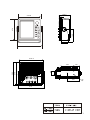
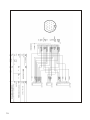
KR-1338/1668 OUTSIDE DRAWING
71
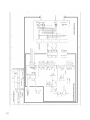
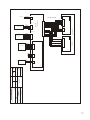
KR-1338/1668 INTERCONNECTION
74
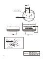
6.1 Antenna Unit Installation Sitting handling considerations
6.2 Display Unit Installation Mounting considerations
6.3 Exchange of Fuse for 24/32V Power Supply
6.4 Checking the Installation
FOREWORD
Thank you for your choice of ONWA MODEL KR-1338/1668 Marine Radar. The
radar is designed and constructed to meet the rigorous demands of the marine environment. However, no machine can perform its intended function unless properfly
installed and maintained. Please carefully read and follow the recommended procedures for installation, operation and maintenance. While this unit can be installed
by the purchaser, any purchaser who has doubts about his or her technical abilities
may wish to have the unit installed by a ONWA representative or other qualified
techician. The importance of a through installation can not be overemphasized.
We would appreciate hearing form you, the end user, about whether user, about
user, about whether we are achieving our purposes. Thank you for considering and
purchasing ONWA equipment.
Features
Your radar has a large variety of functions, all contained in a remarkably small
cabinet.
The main features of the MODEL KR-1338 are.
Traditional ONWA reliability and quality in a compact, lightweight and low-cost
radar.
Durable brushless antenna motor.
On-screen alphanumeric readout of all operational information.
Standard features include EBL (Electronic Bearing Line), VRM (Variable Range
Marker), Guard Alarm, Display Off Center, and Echo Trail.
Watchman feature periodically transmits the radar to check for radar targets
which may be entering the alarm zone.
Ship s position in latitude and longitude and range and bearing to waypoint,
and ship's speed/ heading/course can be shown in the ottom text area.(Requires
a navigation aid which can output such data in IEC 1162 format.)
Zoom feature provided.
1
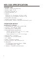
KR-1338 SPECIFICATION
ANTENNA UNIT
1.
2.
3.
4.
5.
Radiator : Slotted waveguide array
Radiator length : 55 cm
Horizontal beamwidth : 4
Vertical beamwidth : 25
Sidelobe :
Within
20 off mainlobe; less than -18 dB
Outside
20 off mainlobe; less than -23 dB
6. Polarization : Horizontal
7. Antenna rotation speed : 24 rpm( 2)
8. Wind resistance : Relative wing speed 100 knots(51.5 m/s)
TRANSCEIVER MODULE
(contained in radome)
1.
2.
3.
4.
Transmitting tube : MSF1421B or MAF1421B
Frequency : 9410 MHz
30MHz
Peak output power : 4kW nominal
Pulselength & pulse repetition rate :
0.08 S, 2100 Hz (0.125, 0.25, 0.5, 0.75, 1.5nm)
0.3 S, 1200 Hz (1.5, 2, 3nm)
0.8 S, 600 Hz (3, 4, 6, 8, 12, 16, 24, 36nm)
5. Warm up time : 1:30 minutes
6. Modulator : FET switching method
7. I.F. : 60MHz
8. Tuning : Automatic or manual
9. Receiver front end : MIC (Microwave IC)
10. Bandwidth :
Tx pulselength 0.3 S and 0.08 S : 25MHz
Tx pulselength 0.8 S : 3MHz
11. Duplexer : Circulator with diode limiter
2
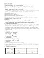
DISPLAY UNIT
1. Indication system : LCD digital display
2. Display : 10.4 LED backlight, 32-bit TFT Color LCD Display
3. Range scale (nm) :
Range, Range interval and no. of Rings:
0.125(0.0625,2), 0.25(0.125,4), 0.75(0.25,3), 1(0.25,4), 1.5(0.5,3), 2(0.5,4),
3(1,3), 4(1,4), 6(2,3), 8(2,4), 12(3,4), 16(4,4), 24(6,4), 36(12,3)
4. Bearing resolution : 4
5. Bearing accuracy : Within 1
6. Range discrimination : Better than 30 m
7. Range ring accuracy : 0.9% or range in use or 8 m, whichever is larger
8. Minimum range : Better than 25 m
9. Markers :
Heading line, Bearing scale, Range ring, VRM, EBL Tuning indicator,
Cursor, Alarm zone, North mark (heading sensor input required)
10. Alphanumeric indication :
Range, Range ring interval, Pulselength, Interference rejection (IR), VRM,
EBL, Stand-by (ST-BY), Radar alarm, Echo stretch (ES), Range to cursor,
Bearing to cursor, Echo trailing (TRAIL), Trail time, Trail elapsed time,
Navigation data (navigation input required), heading (HDG, heading sensor
input required)
11. Vibration :
Vibration Total amplitude :
1 to 12.5 Hz
1.6mm
12.5 to 25 Hz
0.38mm
25 to 30 Hz
0.10mm
12. Temperature :
Antenna unit; -25
to + 70
Display unit; -10
to + 50
13. Humidity :
Relative humidity 93% or less at + 40
14. Power supply & power consumption : 12V, 24V or 32VDC (10.5V to 40
VDC) 60W
15. Compass safe distance :
Standard Compass
Steering Compass
Display unit
0.75m
0.6m
Antenna unit
3.1m
1.75m
3
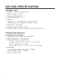
KR-1668 SPECIFICATION
ANTENNA UNIT
1.
2.
3.
4.
5.
Radiator : Slotted waveguide array
Radiator length : 120 cm
Horizontal beamwidth : 1.9
Vertical beamwidth : 22
Sidelobe :
Within
20 off mainlobe; less than -24 dB
Outside
20 off mainlobe; less than -30 dB
6. Polarization : Horizontal
7. Antenna rotation speed : 24 rpm
8. Wind resistance : Relative wing speed 100 knots(51.5 m/s)
TRANSCEIVER MODULE
(contained in antenna)
1. Transmitting tube : MAF1421 or MSF1421
2. Peak output power : 4kW nominal
3. Pulselength & pulse repetition rate :
0.08 S, 2100 Hz (0.125, 0.25, 0.5, 0.75, 1.5nm)
0.3 S, 1200 Hz (1.5, 2, 3nm)
0.8 S, 600 Hz (3, 4, 6, 8, 12, 16, 24, 36, 48, 64nm)
4. Bandwidth :
Tx pulselength 0.3 S and 0.08 S : 25MHz
Tx pulselength 0.8 S : 5 MHz
5. Other : See KR-1338
4
DISPLAY UNIT
1. Range scale (nm) :
Range, Range interval and no. of Rings:
0.125(0.0625,2), 0.25(0.125,4), 0.75(0.25,3), 1(0.25,4), 1.5(0.5,3), 2(0.5,4),
3(1,3), 4(1,4), 6(2,3), 8(2,4), 12(3,4), 16(4,4), 24(6,4), 36(12,3), 48(12,4),
64(16,4)
2. Compass safe distance :
Standard Compass
Steering Compass
Display unit
0.75m
0.6m
Antenna unit
1.0m
0.74m
3. Power supply & power consumption : 12V, 24V or 32VDC (10.5V to 40VDC)
60W
5
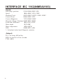
INTERFACE IEC 1162(NMEA0183)
(Input)
Own ship`s position:
GGA>RMA>RMC>GLL
Speed:
RMA>RMC>VIG>VHW
Heading (True):
HDT>HDG*>HDT*>VHW>VHW*
Course (True):
RMA>RMC>VTG
Course (Magnetic):
VTG>RMA*>RMC
Waypoint (Range, Bearing): RMB>BWC>BWR
Loran time difference:
RMA>GLC>GTD
Water depth:
DPT>DBT
Water temperature:
MDA>MTW
XTE:
RMB>XTE>APB
*: Calculated value based Magnetic variation.
(Output)
TLL: On using TLL Key.
RSD: An interval of four seconds.
TTM: ARPA
6
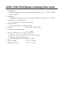
ARPA FUNCTION(Require Heading Data Input)
1. Acquisition
Instant selection of auto or manual acquisition in 0.2 ~ 16nm, relative
speed 100KT.
2. Tracking
Automatic tracking of up to 10 acquired targets betwen 0.1 to 16 nm.
3. Prediction of target motion
True or relative vectors, time scaled.
4. Past position
10 past positions of tracked targets.
5. Alarm
Lost target. CPA/TCPA
6. Automatic tracking range
0.1 ~ 16nm
7. Target information (one target selected)
Distance and bearing from own ship to target
Moving direction and speed
CPA (estimated Closest Time to CPA)
8. Vector length
30 sec.~30 min.
9. Plotting interval
15 sec.~6 min.
7
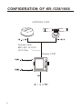
CONFIGERATION OF KR-1338/1668
ANTENNA UNIT
Antenna cable
KRC-003-10/15/20
10/15/20m
Display UNIT
Pin
Pin
8
1. PRINCIPLE OF OPERATION
1.1 What is Radar?
The term "RADAR" is an acronym meaning "RAdio Detection And Ranging".
Although the basic principles of radar were developed during World War II,
echoes as an aid to navigation is not a new development.
1.2 How Ships Determined Position Before Radar
Before the invention of radar, when running in fog near a rugged shoreline,
ships would sound a short blast on their whistles, fire a shot, or strike a bell.
The time between the origination of the sound and the returning of the echo
indicated how far the ship was from the cliffs or the shore. The direction from
which the echo was heard indicated the relative bearing of the shore.
1.3 How Radar Determines Range
Radar determines the distance to the target by calculating the time difference
between the transmission of a radar signal and the reception of the reflected
echo. It is a known fact that radar waves travel at a nearly constant speed of
162,000 nautical miles per second. Therefore the time required for a transmitted
signal to travel to the target and return as an echo to the source is a measure
of the distance to the target. Note that the echo makes a complete round trip,
but only half the time of travel is needed to determine the one-way distance to
the target. This radar automatically takes this into account it making the range
calculation.
1.4 How Radar Determines Bearing
The bearing to a target found by the radar is determined by the direction in
which the radar scanner antenna is pointing when it emits an electronic pulse
and then eceives a returning echo. Each time the scanner rotates pulses are
transmitted in the full 360 degree circle, each pulse at a slightly differentbearing
from the previous one. Therefore, if one knows the direction in whichthe signal
is sent out, one knows the direction from which the echo must return.
1.5 Radar Wave Speed and Antenna Rotation Speed
Note that the speed of the radar waves out to the target and back again as echoes
is extremely fast compared to the speed of totation of the antenna. By the time
radar echoes have returned to the scanner, the amount of scanner rotation after
initial transmitting of the radar pulse is extremely small.
9
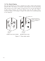
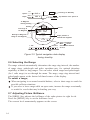
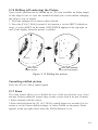
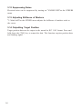
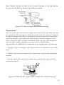
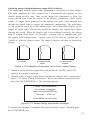
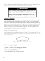
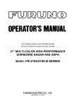
1.6 The Radar Display
The range and bearing of a target is displayed on what is called a Plan Position
Indicator (PPI). This display is essentially a polar diagram, with the transmitting
ship's position at the center. Images of target echoes are received and displayed
at their relative bearings, and at their distance from the PPI center. With a
continuous display of the images of targets, the motion of the transmitting ship
is also displayed.
Heading line
Targets
Range and bearing of
a target, relative to own
ship, are readable on
the PPI
Own ship
(radar)
Own ship
in center
(A) Bird's eye view of situation
(B) Radar picture of (A)
Figure 1-1 How radar works
10
2. BASIC OPERATION
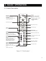
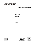
2.1 Control Description
Omnipad
Shifts cursor, VRM and EBL;
select items and options on
menu.
Brief press:
Displays the data of target
selected with the cursor
Long press:
Terminates plotting of the target
selected with the cursor.
(1) Acquires the target selected
with the ominipad.
(2) Registers selection on
menus.
Opens/closes menus.
Sets guard zone area.
Sets radar range.
Selects
EBL1/EBL2/VRM1/VRM2
Enables/erases
EBL1/EBL2/EBL3/EBL4.
Control:
Adjusts sensitivity.
Switch:
Temporarily erases heading
line (and north mark if displayed).
Outputs target position data.
Automatically reduces sea and
rain clutters.
Control:
Reduces sea clutter.
Switch*:
(Long press) Shifts your vessel`s
position to cursor location.
(Brief press) Doubles size of
area between your vessel and
location selected by cursor.
Adjusts display brilliance.
Sets radar in stand-by;
transmits radar pulse.
Control:
Reduces rain clutter.
Switch*:
Displaces the EBL origin.
Turns power on/off.
Lights when the economy mode
is on.
*Default switch function.
Figure 2-1 Control panel
11
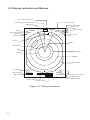
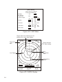
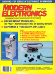
2.2 Display Indication and Markers
Echo trail elapsed time
Tuning indicator
Heading (requires heading data)
Heading line
Range
Range ring interval
Pulselength
Display mode
HDG 234.5
.125NM
AUTO
TRAIL
25:38
30M
G OUT
ZOOM
ES
Echo trail time
Guard zone
Zoom
Echo Stretch
*
.0625
SP
HU
OFFCENTER
Off center
Cursor
EBL2
Guard zone
EBL1
Range ring
VRM1
VRM2
North mark
A/C AUTO
EBL1 bearing
EBL2 bearing
A/C
AUTO
EBL
345.6 R
23.0 R
1.5 NM
13.5 R
0.06
0.142 NM
IR2
VRM
0.048NM
0.100NM
Cursor bearing
Cursor range
Figure 2-2 Display indications
12
Interference rejector
VRM1 range
VRM2 range
2.3 Turning the Radar On/Off
Press the [POWER] key to turn the radar on or off.
The control panel lights and a timer displays the time remaining for warm up of
the magnetron (the device which produces radar pulses), counting down from 1:30
to 0:01.
2.4 Transmitting
After the power is turned on and the magnetron has warmed up, STAND-BY
appears at the screen center. This means the radar is now fully operational. In
stand-by the radar is available for use at anytime - but no radar waves are being
transmitted. Press the [ST-BY/TX] key to transmit. When transmitting, any echoes
from targets appear on the display. This radar displays echoes in eight tones of
green according to echo strength.
2.5 Stand-by
When you won't be using the radar for an extended period, but you want to keep
it in a state of readiness, place it in stand-by by pressing the [ST-BY/TX] key.
The display shows "STAND-BY,"navigtion data, or goes into the economy
mode depending on menu setting. (More on menu operation later.)
Economy mode
The CRT can be set to automatically turn itself off when in stand-by, to reduce
power consumption. This feature is called the "economy mode." Power consumption in the economy mode is 28W. When economy mode is no, the lamp next to the [POWER] key lights.
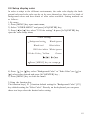
Navigation data display during stand-by
If a navigation aid inputs navigation data to this radar, navigation data can be
displayed during stand-by. You can turn the navigation data display on/off through the menu. Figure 2-3 shows a typical navigation data display during standby.
Note 1:Availability of a particular display item depends on incoming data.
Note 2:When Range to Waypoint reaches 0.1nm, the WPT mark jumps to dead
ahead even though a difference may exist between heading and BRG to WPT.
Note 3:When cross track error exceeds 1 nm on either side, the XTE mark starts blinking.
13
SPEED
Speed
DEPTH
Depth
TRIP
10.5
Kt
125
m
Time-to-go to Stand-by
ST-BY
000.3nm
TEMPERATURE
Trip distance since power on
+17.3
E
To Waypoint
bearing heading
HDG
Heading
092.5
Course
CRS 180.0 M
Time-to-go to
TO Waypoint
WPT
BRG
RNG
N
Bearing TO Waypoint
TTG 01:08
45.0 M
12.0NM
S
OWN SHIP
LAT
30 00 .00N
LON 135 00.00E
Ship's position in
latitude and longitude
Range to TO Waypoint
XTE
R 0.3NM
W
L XTE
1.0
0.5
XTE R
0.5
Cross Track Error
Mark " " shows
direction and amount
of error.
1.0
Figure 2-3 Typical navigation data display
during stand-by
2.6 Selecting the Range
The range selected automatically determines the range ring interval, the number
of range rings, pulselecgth and pulse repetition rate, for optimal detection
capability in short to long ranges. You can select which ranges and pulselength
(for 1 mile range) to use through the menu. The range, range ring interval and
pulselength appear at the botton left-hand corner of the display.
To select a range;
When navigating in or around crowded harbors, select a short range to watch for
possi ble collision situations.
If you select a lower range while on open water, increase the range occasionally
to watch for vessels that may be heading your way.
2.7 Adjusting Picture Brilliance
The [BRILL] key adjusts the brilliance of the radar picture in eight levels.
Press the [BRILL] key to set the brilliance level.
The current level momentarily appears on the screen.
14
2.8 Setup display color
In order to adapt to the different environments, the radar echo display the background color and echo color can be set by users themselves, there are five kinds of
background colors and three kinds of echo colors available. Setting methods are
as follows:
1.By menu
1) Press [MENU] key open main menu;
2) Select ''OTHER MENU'' and press [ACQ/ENTER] key;
3) Press [ ]or [ ] key select ''22.Color setting'' & press [ACQ/ENTER] key
open the color setup menu;
Color setting
Background setting
Black/red
Black/green
Blut/white
DK blue/white White/green
2.Echo Color Yellow
Green
Press [MENU] key to escape
4) Press [ ] or [ ]key select ''Background Color'' or ''Echo Color'',use [ ] or
[ ] select color desired and press [ACQ/ENTER] key ;
5) Press [MENU] key to close the menu.
2.Using the function key
The function keys [ F1 ] function default setting for ''Background Color'' ,[F2]
key default setting for ''Echo Color''. Directly on the keyboard you can press
these two keys select the desired color setting.
15
2.9 Adjusting Receiver Sensitivity
The [GAIN] control adjusts the sensitivity of the receiver. It works in precisely
the same manner as the volume control of a broadcast receiver, amplifying the
signals received. The proper setting is such that the background noise is just
visible on the screen. If you set up for too little sensitivity, weak echoes may
be missed. On the other hand excessive sensitivity yields too much background
noise; strong targets may be missed because of the poor contrast between desired
echoes and the background noise on the display. To adjust receiver sensitivity,
transmit on long range, and adjust the [GAIN] control so background noise is
just visible on the screen.
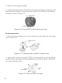
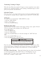
2.10 Adjusting the A/C SEA Control (reducing sea clutter)
Echoes from waves can be troublesome, covering the central part of the display
with random signals known as "sea clutter." The higher the waves, and the higher
the scanner above the water, the further the clutter will extend. Sea clutter appears
on the display as many small echoes which might affect radar performance. (See
the Figure 2-3.) When sea clutter masks the picture, adjust the A/C SEA control to
reduce the clutter.
How the A/C SEA control works
The [A/C SEA] control reduces the amplification of echoes at short ranges (where
clutter is the greatest) and progressively increases amplification will be normal at
those ranges where there is no sea clutter.
16
Adjusting the A/C SEA control
The proper setting of the A/C SEA should be such that the clutter is broken
up into small dots, and small targets become distinguishable. If the control is set
Too low, targets will be hidden in the clutter, while if it is set too high, both sea
clutter and targets will disappear from the display. In most cases adjust the conRol until clutter has disappeared to leeward, but a little is still visible windward.
1. Confirm that the sensitivity is properly adjusted, and then transmit on short
range.
2. Adjust the [A/C SEA] control so small targets are distinguishable but some
clutter remains on the display.
Sea clutter at
display center
A/C SEA control adjusted;
sea clutter suppressed.
Figure 2-4 How to adjust the STC control
Tip for adjusting the A/C SEA
A common mistake is to over-adjust the circuit so all the clutter is removed. As
an example set up for maximum STC. You will see how the center of the display
becomes dark. This dark zone can be dangerous (targets may be missed),
especially if the sensitivity is not properly adjusted. Always leave a little clutter
visible on the display to be sure weak echoes will not be suppressed. If there is
no clutter visible on the display, turn off the circuit.
17
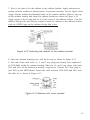
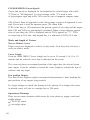
2.11 Apply the A/C RAIN (reducing rain clutter)
The vertical beamwidth of the antenna is designed to see surface targets even
when the ship is rolling. However, by this design the unit will also detect rain
clutter (rain, snow, hail, etc.) in the same manner as normal targets. Figure 2-4
Shows the appearance of rain clutter on the Display.
Adjusting A/C RAIN
When rain clutter masks echoes, adjust the [A/C RAIN] Control, This control splits up these unwanted echoes into a speckled pattem, making recognition of soild
targets easier.
Appearance of rain clutter
A/C RAIN control adjusted;
rain clutter suppressed.
Figure 2-5 Effect of A/C RAIN
Note: In addition to reducing clutter, the [A/C RAIN] control can be
used in fine weather to clarify the picture when navigating in
confined waters. However, with the circuit activated the receiver is
less sensitive. Therefore, turn off the circuit when its function is not
required.
Automatic adjustments of A/C SEA and A/C RAIN
Push the [A/C Auto] key. "A/C Auto"appearstat the bottom left-hand corner of
the display when the A/C AUTO circuit is on. You can fine tune by adjusting the
[A/C SEA], [A/C RAIN] and [GAIN] controls.
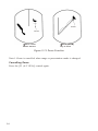
2.12 Erasing the Heading Line, North Mark
The heading line or north mark (available with gyrocompass connection) may occasionally mask a target. To view the target, you can temporarily erase the heading
line and north mark by pressing and holding down the [GAIN (HM OFF)] control.
Release the control to re-display the marks.
18
Heading
Line
North mark
Figure 2-6 Heading line and north mark
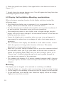
2.13 Measuring the Range
You can measure the range to a target three ways: by the range rings, by the
cursor, and by the VRM (Variable Range Marker).
By range ring
Count the number of rings between the center of the display and the target.
Check the range ring interval and judge the distance of the echo from the echo
from the inner edge of the nearest ring.
By cursor
Operate the omnipad to place the cursor intersection on the inside edge of the
garget echo, The range to the target, as well as the bearing, appears at the
bottom right-hand corner of the display.
By VRM
1. Press the [EBL/VRM SELECT] key to circumscribe a VRM readout (at the
bottom center).Each press of the key selects the readout of EBL1,EBL2,VRM1
or VRM2 in that order.
EBL
345.6 R
23.0 R
VRM
5.3 NM
12.5 NM
Figure 2-7 Display bottom, showing location
of EBL and VRM readouts
2. Press the [EBL/VRM CONTROL] key enable control of the VRM by the
omnipad.
3. Operate the omnipad to place the outside edge of the VRM on the inside
edge of the target.
4. Check the VRM readout at the bottom right-hand corner of the display to
find the range to the target.
5. To erase the VRM, press and hold down the [EBL/VRM CONTROL] key .
19
To erase the VRM, press and hold down the [EBL/VRM CONTROL] key about
two seconds.
Range
Range ring
Interval
6.0 NM
2.0
VRM1
Target
Cursor
Cursor range
VRM2
4.0 NM
VRM
4.0 NM
3.0 NM
VRM1
Range
VRM2
Range
Figure 2-8 Measuring range by the cursor,
range rings and VRM
Note: You can display the range readout of the VRM and cursor in nautical
miles, statute miles or kilometers. For details see the next chapter
2.14 Measuring the Bearing
There are two ways to measure the bearing to a target: by the cursor, and by
the EBL (Electronic Bearing Line).
By cursor
Operate the omnipad to bisect the target with the cursor intersection. The bearing
to the target appears at the bottom of the display.
By EBL
1. Press the [ERL/VRM LECT] key to circumscribe an EBL readout (at the bottom left-hand corner). Eash press of the key selects the readout of EBL1,
EBL2,VRM1 or VRM2 in that order.
2. Press the [EBL/VRM CONTROL] key to enable control of the omnipad.
3. Operate the omnipad to bisect the target with the EBL.
4. Check the EBL readout at the bottom left-hand corner of the display to find
the hearing to the target.
5. To anchor the EBL, press the [EBL/VRM CONTROL] key.
To erase the EBL and its readout; press and hold down the [EBL/VRM CONTROL] key about two seconds.
20
Target
Cursor
EBL1
EBL2
Cursor
Bearing
EBL1 bearing
EBL1 bearing
EBL
40.0 R
40.0 R 4.0 NM
135.0 R
Figure 2-9 How to measure bearing by EBL and cursor
Note: The bearing readout for the EBL and the cursor can be display in relative
or true bearing (true bearing requires heading sensor input) For north up and curse up display modes the bearing reference is always true. For details see the
next chapter.
Tips for measuring bearing
Bearing measurements of smaller targets are more accurate; the center of
larger target pips is not as easily identified.
Bearings of stationary or slower moving targets are more accurate than
Bearings of faster moving targets.
To minimize bearing errors keep echoes in the outer half of the picture by
changing the range scale; angular difference becomes difficult to resolve as
a target approaches the center of the display.
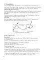
2.15 Using the Offset EBL
The offset EBL provides two functions: predict collision course of radar target and
measure the range and the bearing between two targets.
Predicting collision course
1. Press the omnipad to place the cursor on the center of the target.
2. Press the [EBL/VRM SELECT] key to choose EBL1 readout and then press the
[EBL/VRM CONTROL] key.
3. Select EBL OFFSET on the menu and press the [ACQ/ENTER] key.
4. Press the [EBL/VRM CONTROL] key.
5. Operate EBL1 so it passes through the center of the target.
If the target tracks along the EBL towards the center of the display (you vessel's
Position), the target may be on a collision course.
To cancel, select EBL OFFSET and press the [ACQ/ENTER] key.
21
6.0 NM
2.0
EBL1 origin
(Initial position
of target)
VRM1
Target moved
Here.
EBL1
bearing
Offset EBL
(EBL1)
EBL
70.0
VRM1
6.0 NM
R
VRM1
range
Figure 2-10 Predicting collision course by
using the offset EBL
Measuring range and bearing between two targets
The procedure which follows shows how to measure the range and bearing between target "A" and target "B" in Figure 2-11.
1. Press the omnipad to place EBL1's origin (cursor) on the center of target "A".
2. Press the [EBL/VRM SELECT] key to choose EBL1 readout and then press the
[EBL/VRM CONTROL] key.
3. Select EBL OFFSET on the menu and press the [ACQ/ENTER] key. EBL1's
origin shifts to cursor.
4. Press the [EBL/VRM CONTROL] key.
5. Press the onmipad to bisect target "B" with EBL1. Check the EBL1 readout to
find the bearing between target "A" and target "B".
6. Press the [EBL/VRM SELECT] key to choose VRM1 readout. Press the omnipad to place the outside edge of VRM1 on the inside edge of target "B". Check the
VRM1 readout to find the range between target "A" and target "B".
7. To cancel, select EBL OFFSET on the menu and press the [ACQ/ENTER] key.
EBL1
VRM1
EBL1
Bearing
70.0
R
VRM
4.5 NM
VRM1
Range
Figure 2-11 Measuring the range and bearing
between two targets by using the offset EBL
22
2.16 Shifting (off centering) the Picture
Your vessel's position can be shifted up to 75% (not available on 48nm range)
of the range in use to view the situation around your vessel without changing
the range or size of targets.
1. Press the omnipad to set cursor where desired.
2. Press the [F1(A/C SEA)] control if its function is set for SHIFT (default setting), or select SHIFT on the menu. OFFCENTER appears at the top right corner of the display when the picture is shifted.
Cursor
Cursor
Place cursor
Where desired
Press [OFF CENTER]
key to off center display
Figure 2-12 Shifting the picture
Cancelling shifted picture
Press the [F1(A/C SEA)] control again.
2.17 Zoom
The zoom feature allows you to double the size of the area between your vessel
and any location within the current range to take a closer look at an area of interst.
1.Select location with the cursor.
2.Press and hold down the [F1 (A/C SEA)] control about two seconds if its function is set for Zoom (default setting), or select ZOOM on the menu, Zoom
appears at the top right corner when the ZOOM function is on .
23
Cursor
Cursor
Place cursor
Where desired
Press [ZOOM]
key to zoom
Figure 2-13 Zoom Function
Note1: Zoom is cancelled when range or presentation mode is changed.
Cancelling Zoom
Press the [F1 (A/C SEA)] control again.
24
3. MENU OPERATION
3.1 Basic Menu Operation
The menu mostly contains less-often used functions which once preset do not
require regular adjustment. To open or close the menu, press the [MENU] key.
You can select items on the menu with the omnipad. The complete menu appears on page AP-1.
1. Press the [MENU] key to display the main menu.
Sel by omnipad & press ENT.
RINGS
EBL
OFFSET
SHIFT
ZOOM
MODE
DISP
DATA
ECHO
TRAIL
ECHO
STRTCH
Change brill
from 3 to max.
ARPA
MENU
OTHER
MENU
Figure 3-1 Main menu
2. Press the omnipad to select the item. For example, select RINGS. A message
appears at the bottom of the menu window.
3. Press the [ACQ/ENTER] key to select setting, Each time this key is pressed, the
message changes, For the RINGS menu, the message sequence is as shown below.
Change brill from Off to 1.
Change brill from 1 to 2.
Change brill from 2 to 3.
Change brill from 3 to max.
Change brill from max to Off.
Figure 3-2 Messages for RINGS menu
4. Press the [MENU] key to close the menu.
3.2 Selecting the presentation mode
This radar provides four presentation modes. Head-up, course-up, north-up and true
motion.
1. Press the [MENU] key.
25
2. Operate the omnipad to select "MODE".
3. Press the [ACQ/ENTER] key.
With heading sensor connection the display and the display and the display mode
indication at the top lefthand corner of the display change in the sequence of HU
(heading up), CU (course up), NU (north up) and TM (true motion)when the
[ACQ/ENTER] key is pressed. If there is no heading sensor connection, the display mode is always HU.
4. Press the [MENU] key to close the menu.
Note: The radar begins operation with last selected display mode (except course
up) whenever the unit is turned on. Note however that head up is selected when
course up was the last used mode.
Head up
The picture is oriented so the heading line is at the top of the display. This mode
is useful for navigation in congested waters.
Course up
The course up mode shows Ship's heading by the heading line, at the top of the
display. To get heading desired, steer vessel in direction desired, and the show"
CU"at the top lefthand corner of the display.
North up
North is at the top of the display and the heading line moves with Ship's heading.
This mode is useful for determining ship's position and as a navigation monitor on
a nautical chart. The picture is stabilized against yaw of vessel, thereby reducing
of target echoes.
True motion
True motion displays own ship and moving objects in their true motion.
3.3
Magnifying long range echoes (echo stretch)
Normally, the reflected echoes from long range target appear on the display as
weaker and smaller blips even though they are compensated by the radar's internal
circuitry. The echo stretch function magnifies these small blips in all ranges. Two
types of echo stretch are available: ES1 which stretches echoes in bearing direction
and ES2 which stretches them in both range and bearing directions.
To turn the echo stretch on or off;
1. Press the [MENU] key to open the menu.
2. Select "ES".
3.Each press the [ACQ/ENTER] key changes the echo stretch function in the sequence of ES1,ES2 and OFF. ES1 or ES2 appears at the top right-hand corner of
the display when echo stretch is on.
26
Bearing
direction
Bearing
direction
Range
direction
Echo stretch 1
Echo stretch 2
Figure 3-3 Echo stretch
Note: This function magnifies not only targets but also sea clutter and radar interference. For this reason be sure the controls for adjustment of sea clutter and radar interference are properly adjusted before activating the echo stretch.
Note: ES1 is not available on Short Range.
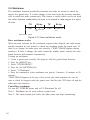
3.4 Echo Trail
You can show the movement of all radar targets relative to your vessel in afterglow
vessel in afterglow. This function is useful for alerting you to possible collision
situations.
Starting echo trail
1. Press the [MENU] key to open the menu.
2. Select "ECHO TRAIL"by the omnipad.
3. Select "ACTIVATE"by pressing the [ACQ/ENTER] key.
Figure 3-4 How the echo trail feature work
TRAIL, the echo trail time selected (on "OTHER MENU") and elapsed time
appear at the top right-hand corner of the display. Then, afterglow starts extending
from all target.
Note: Trails are restarted when range or mode is changed or zoom or shift is turned on.
27
Fixed time trail
1. When the elapsed time clock counts up to the trail time selected, the elapsed
time display freezes.
2. The oldest portions of trails are erased so only the latest trail, equal in length
to the trail time selected, is shown.
3. Trail continues.
For example, the one minute trail time is selected. When the elapsed time clock
counts up to 60 seconds, the elapsed time clock counts up to 60 seconds, the elapsed time display freezes at "60,"but the latest one minute of trail are erased
and then trail continuous.
Continuous trail
The maximum continuous trail time is 99 minutes and 59 seconds. When the elapsed time clock counts up to that time the elapsed time display is reset to zero and
trail begins again. Display is reset to zero and trail begins again.
Cancelling echo trail
Select"OFF(deactivate)"at "ECHO TRAIL"on the menu.
Changing trail attributes
Trail gradation and trail time can be selected on the OTHERS menu.
Item In
OTHERS
menu
Description
Trails can be shown in
single or multiple
gradations. Multiple paints
trails getting thinner with
Trail Tone
time just like the afterglow
on an analog PPI radar.
Single
Multiple
Trail time can be set for 15 sec ,.
Trail Time
30 sec ., 1 min., 3 min., 6min.,
15min., 30 min., or continuous.
Table 3-5 Trailing attributes
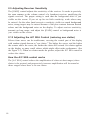
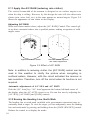
3.5 Suppressing Radar Interference
Radar interference may occur when near another shipborne radar operating in the
same frequency hand as you radar. Its on-sereen appearance is many bright dots
either scattered at random or in the form of dotted lines extending from the center
to the edge of the display. Figure 3-6 illustrates interference in the from of curved
spokes. Interference effects are distinguishable from normal echoes because they
do not appear in the same place on successive rotations of the antenna.
28
Figure 3-6 Radar interference
Four levels of interference are available, including off; IR1,IR2,IR3 and OFF,IR3
provides the highest level of rejection.
1. Press the [MENU] key.
2. Select "OTHER MENU"and press the
[ACQ/ENTER] key.
3. Select "6. Int Reject".
4. Select level desired by operation the omnipad.
5. Press the [ACQ/ENTER] key.
6. Press the [MENU] key to close the menu.
[ OTHERS ]
select item by omnipad
and press ENTER key.
1. Panel Dimmer
2. Mark brill
3. HD Mark
4. Characters
5. Trail Tone
6. Int Reject
7. Pulselength
8. Noise Reject
9. Traim Time
1
2
3
2
3
1
1
2
3
1
2
3
Single
Multi
Off
1
2
Short
Long
Off
On
15S
30S
1M
3M 6M
15M
30M
10. Tune
Auto
Manu
11. Disp Data
Off
Nav
ARP
12. WPT Mark
Off
On
13. EBL Ref
Ret
Ture
14. VRM Unit
nm
km
sm
15. Watchman
Off
5M
10M
16. STBY Disp
Norm
Econo Nav
17. Guard Mode
In
Out
18. Cursor Posi
R/B
L/L
19. Alm sense LV
Low
Mid
Hig
20. Dead Sector
Off
On
21. Range
1/8 1/4 1/ 2 3/ 4 1 15
2 3 4
5
8 12 16 24
22. Color setting
23. Self Test
24. Installation Setup
4
4
4
4
3
Cont
All
20M
36
Figure 3-7 OTHER MENU
3.6 Selecting Pulsewidth
Pulsewidth is the transmission time of a Single radar pulse. The longer the pulsewidth the greater the direction range capability, however range accuracy and range
resolution are reduced.
29
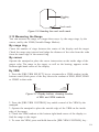
3.7 Guard Alarm
The guard alarm allows the operator to set the desired range and bearing for a
guard zone. When ships, islands, landmasses, etc. Violate the guard zone an audible
alarm sounds and the offending target brinks to call the operator's attention.
Selection of guard zone type
The guard alarm can be set to sound when a target either enters or exits the guard
zone. You can select which type of guard alarm you want through the menu.
In alarm
The alarm sounds on targets entering the guard zone."G(IN)"appears at the top
right-hand corner when the In alarm is selected.
Out alarm
The alarm sounds on targets exiting the guard zone. "G(OUT)"appears at the
top right-hand corner when the Out alarm is selected.
Dashed line
no alarm
Guard
IN ALARM
OUT ALARM
Figure 3-8 In and Out alarm
Setting a guard zone
Preparation
1. Press the [MENU] key, and the select "OTHER MENU"and pressing the
[ACQ/ENTER] key.
2. Select "17. Guard Mode"and "In"(alarm on target entering zone) or "Out"
(alarm on target exiting zone) by operating the omnipad.
3. Press the [ACQ/ENTER] key.
4. Press the [MENU] key to close the menu.
To set a guard zone
1. Mentally create the guard zone you want to set.
2. Operate the onipad to set the cursor on point A or B. Press the [GUARD] key.
"*G(IN)", with asterisk blinking, appears at the top right-hand corner of the
display. See Figure 3-9 (2).(The asterisk indicates the guard zone is partially set.)
3. Operate the omnipad to set the cursor on point C or D. See Figure 3-9 (3).
4. Press the [GUARD] key. The asterisk disappears. See Figure 3-9 (4).
30
Asterisk blinking
Guard zone to set
A
Drag cursor here.
1
Drag cursor to top left corner of
zone and press [GUARD].
Mentally create the
guard zone to set.
Guard zone
Guard zone completed.
Drag cursor to bottom right corner of zone
and press [GUARD].
Figure 3-9 How to set the guard zone
Silencing the audible alarm
Any radar targets violating the guard zone will trigger the audible alarm. You can
silence the audible alarm by pressing the [GUARD] key. When this is done,
"G(ACKN)"replaces"G IN "This means the alarm is acknowledgrd. Press
the key again to reactivate the alarm.
Cancelling the guard zone and guard alarm
Press and hold down the [GUARD] key until the guard zone disappears.
Notes on the guard alarm
The alarm is useful anti-collision aid, but does not relieve the operator of the
responsibility to also keep a visual lookout for possible collision situations.
When the radar range is less than one half of the guard zone range, the guard
zone disappears and "G(IN)"or "G OUT "appears in inverse video. If this
happens, raise to re-display the guard zone.
A target echo does not always mean a landmass, reef ,ships or surface objects
but can imply returns from sea surface or precipitation. As the level of these returns varies with environment, the operator should properly adjust the A/C SEA, A/C
RAIN and GAIN to be sure the alarm system does not overlook target echoes.
31
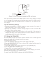
3.8 Watchman
The watchman function periodically transmits the radar for minute to check for
targets in a guard zone. If it finds change in the zone from the previous transmission it sounds the radar continuously. This feature is useful when you do not need
the radar's function continuously but want to be alerted to radar targets in a specific area.
TX
St-by
TX
St-by
1min
5 10 or 20
min
1 min
5,10 or 20
min
Watchman starts.
Figure 3-10 How watchman works
How watchman works
When the time selected for the watchman restperiod has elapsed, the radar automatically transmits for one minute to check the condition inside the guard zone. If
there is no change, the radar goes into stand-by ("WHTCHMAN"appears during
stand-ny.) If there is change, the radar sounds the audible alarm, cancels the watchman function and transmits continuously.
Turning on watchman
1. Create a guard zone (usually 360 degrees) with the guard alarm function.
2. Press the [MENU] key.
3. Select "OTHER MENU".
4. Press the [ACQ/ENTER] key.
5. Select "15.Watchman".
6. Press the omnipad to select watchman rest period; 5 minutes, 10 minutes or 20
minutes.
"WATCHMAN"appears at the top of the screen, the radar transmits for one minute to check for targets inside the guard zone. And the the CRT shuts off and the
radar goes into stand-by.
Cancelling watchman
Go into the "OTHERS"menu, and set"15.Watchman"for off.
Note 1: Watchman can be used without a guard zone.
Note 2: The alarm sounds just before the radar starts and stops transmitting.
32
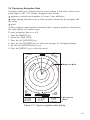
3.9 Displaying Navigation Data
Navigation data can be displayed at the screen bottom if this radar receives navigation input in IEC 1162 format. Navigation data include.
position in latitude and longitude or Loran-C time difference
range, bearing and time-to-go to both waypoint selected on the navigator and
the cursor.
speed.
(If the navigation input includes destination data, waypoint position is denoted on
the radar display by a dashed ring.)
To turn navigation data on or off;
1. Press the [MENU] key.
2. Select the "DISP DATA".
3. Press the [ACQ/ENTER] key.
4. Press the [ACQ/ENTER] key to select the message for Navigation display.
5. Prss the [ACQ/ENTER] key to set.
6. Press the [MENU] key to close the menu.
AUTO
125 NM
HDG 234.5
TRAIL
25:38 30M
G(OUT)
ZOOM
ES1
*
0625
sp
HU
Waypoint Mark
A/C
AUTO
EBL
345.6 R
23.0 R
OWN SHIP
34 56.12N
135 34.56E
SPD 35.OKT
1.5 NM
13.5 R
0.06
0.142NM
+ CURSOR
34 29.38N
136 35.77E
TTG 01:00
VRM
0.048NM
0.100NM
WAYPOINT
0.09 NM
50.0 M
TTG 00:20
Navigation
Data
Figure 3-11 Typical navigation data display
33
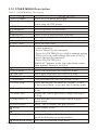
3.10 OTHER MENU Description
Table 3-2 OTHER MENU Description
1.Panel Dimmer
2.Mark Brill
3. HD Mark
Characters
. Trail Tone
. Int Reject
. Pulselength
8 .Nosie Reject
. Trail Time
10 .Tune
. Disp Data
12 .WPT Mark
. EBL Ref
14 .VRM Unit
15.Watchman
Select level of panel backlight.
Select brilliance of VRM, EBL, cursor,
guard zone and WP marks.
Select brilliance of heading mark.
Select brilliance of characters.
Select brillance of echo trails.
Select level of interference rejection.
Select pulselength for 1.5 and 3 mile ranges.
Select " On " to reject nosie.
Select the trail time.
Select automatic or manual tuning.
To tune manually;
1 .Select"Menu"by the omnipad.
2 .Press the [ENTER] key to enable manual tuning.
3 .While pressing and holding down the [GAIN]
control operate the omnipad.
4 .Press the [ENTER] key.
"MANUAL"appears at the top right-hand corner
when manual tuning is in effect.
Select the down sourse to display.
Select " On " to display the waypoint mark.
Select EBL reference for relative or true.
Select " On " to display the waypoint mark.
Turn watchman on (set rest period) or off.
16 .STBY Disp
Select the display on stand-by; display " STBY "
or navigation data, or go into the economy mode.
17.Guard Mode
Select condition which triggers guard alarm; in
or out.
Display the cursor position in range/bearing or
at/long.
Select minimau echo strength which triggers
guard alarm.
Select " On " to display the dead sector.
18 .Cursor Posi
19.Alm sense LV
20 .Dead Sector
.Range
Select ranges in use.
.Color setting
Set background color & Echo color
23.Self Test
Test keys, ROM and RAM, check antenna rotation
speed, and display program number
.Installation Setup Go to the installation setup menu.
34
3.11 Function Keys
The function keys(F1 and F2) work like the auto-dialing feature of a telephone, automatically executing the function assigned to them. The function can
be turned off by pressing appropriate function key again.
Default settings
F1: Background Color
F2: Echo Color
How to register menu items
1.
2.
3.
4.
5.
Press the [MENU] key.
Press [A/C SEA] (F1) or [A/C RAIN] (F2) to open the function menu.
Select function desired.
Press the [ACQ/ENTER] key.
Press the [MENU] key to close the menu.
[SETTING FOR F1 KNOB]
Sel by omnipad & press ENT.
<Press MENU key to escape>
SHIFT/
ZOOM
EBL
OFFSET
SHIFT
ZOOM
RINGS
MODE
DISP
DATA
STBY
DISP
INT/
REJECT
NOISE
REJECT
PULSE
LENGTH
ECHO
STRTCH
TRAIL
ON/OFF
TRAIL
TIME
TRAIL
TONE
TUNE
A/M
GUARD
IN/OUT
ALARM
LEVEL
DEAD
SECTOR
WATCH
MAN
PANEL
DIMMER
MARK
BRILL
CHARA
CTERS
OTHER
MENU
EBL
REF
VRM
UNIT
NAV
TALKER
WPT
MARK
OWN
POSITN
CUSOR
POSITN
VECTOR
LENGTH
VECTOR
REF
COLLI
SION
AUTO
ACQ
B/GR
COLOR
HIS
TORY
Figure 3-12 Function menu
Note: In function 2 setup menu ,the item is " ECHO COLOR"
35
3.12 Suppressing Noise
Electrical noise can be suppressed by turning on "8.NOISE REJ"on the OTHERS
menu.
3.13 Adjusting Brilliance of Markers
"2. Mark brill"on the OTHER menu adjusts the brilliance of markers such as
the cursor.
3.14 Outputting Target Position
Target position data can be output to the navaid in IEC 1162 format. Press and
hold down the [TLL] key to output the data. This function requires position data
and heading signal.
36
4. FALSE ECHOES
Occasionally false echoes appear on the screen at positions where there is no
target. In some cases the effects can be reduced or eliminated. The operator
should familiarize himself or herself with the appearance and effects of these
false echoes, so as not to confuse them with echoes from legitimate contacts.
4.1 Multiple Echoes
Multiple echoes occur when a short range, strong echo is received from a ship,
bridge, or breakwater. A second, a third or more echoes may be observed on the
display at double, triple or other multiples of the actual range of the target as
shown in Figure 4-1. Multiple reflection echoes can be reduced and often removed
by decreasing the sensitivity or properly adjusting the A/C SEA.
True
Echo
Own ship
Multiple
echo
Figure 4-1 Multiple echoes
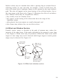
4.2 Side-lobe Echoes
Every time the antenna rotates, some radiation escapes on each side of the
beamcalled "side-lobes." If a target exists where it can be detected by the
side-lobes as well as the main-lobe, the side-lobe echoes may be represented on
both sides of the true echo at the same range, as shown in Figure 4-2. Side-lobes
show usually only at short ranges and from strong targets. They can be reduced
through careful reduction of the sensitivity or proper adjustment of the A/C SEA.
37
True echo
Main-lobe
Side-lobe
Sprious
target
Antenna
Figure 4-2 Side-lobe echoes
4.3 Indirect Echoes
Direct
path
Target
Heading
Iine
Indirect
path
Indirect
path
Obstruction
Antenna (mast,funnel
etc.).
Target
Direct
path
Indirect
echo
True
echo
Heading
Iine
Own
ship
True
echo
Bridge
Indirect
echo
Indirect
echo
Figure 4-3 Indirect echoes
38
Indirect echoes may be returned from either a passing ship or returned from a
reflecting surface on your own ship, for example, a stack. In both cases, the
echo will return from a legitimate contact to the antenna by the same indirect
path. The echo will appear on the same bearing of the reflected surface, but at
the same range as the direct echo. Figure 4-3 illustrates the effect of an indirect
echo. Indirect echoes may be recognized as follows :
they usually occur in a shadow sector
they appear on the bearing of the obstruction but at the range of the
legitimate contact
when plotted, their movements are usually abnormal, and
their shapes may indicate they are not direct echoes.
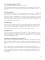
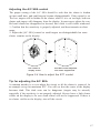
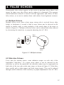
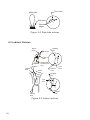
4.4 Blind and Shadow Sectors
Funnels, stacks, masts, or derricks in the path of antenna may reduce the
intensity of the radar beam. If the angle subtended at the antenna is more than
a few degrees a blind sector may be produced. Within the blind sector small
targets at close range may not be detected while larger targets at much greater
ranges may be detected. See Figure 4-4.
Vessel taller
than wharf
Wharf
Mast, etc. In
path of radar
beam
Wharf
Blind sector
(no echo)
Size of blind sector
depends on target
size and range.
Figure 4-4 Blind and shadow sectors
39
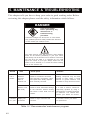
5. MAINTENANCE & TROUBLESHOOTING
This chapter tells you how to keep your radar in good working order. Before
reviewing this chapter please read the safety information which follows.
DANGER
Turn off the power
before performing any
maintenance or
troubleshooting
procedure.
Hazardous voltages can shock, burn or cause death.
Only qualified personnel totally famillier with electrical
circuits should work inside the units.
RF RADIATION HAZARD
The radar antenna emits high frequency radio radiation
which can be harmful, particularly to your eyes. Never
look directly into the antenna from a distance of less than
two feet when the radar is in operation as you could
injure the cornea of your eyes. Always make sure the
radar is set to stand-by or is turned off before starting
work on the antenna unit.
Period
3 to 6
months
Item
Check point
Exposed
nuts and
bolts on
antenna unit
Check for corroded or loosened
nuts and bolts. If necessary, clean
and repaint them thickly. Replace
them if heavily corroded.
Sealing compound may be used
instead of paint. Apply a small
amount of grease between nuts
and bolts for easy removal in future.
Radome cover
(KR-1338)
Check for wear. Permanent damage
to the antenna's internal circuitry
will result if water leaks into the
If a crack is found it should be
temporarily repaired by using a
samll amount of sealing compound
or adhesive. You should then
contact your dealer for service.
radome.
6 months
to 1 year
Remarks
Display unit
connectors
Check for tight connection and
corrosion.
If corroded, contact your dealer
for replacement.
Table 5-1 Recommended maintenance program
40
5.1 Preventative Maintenance
Regular maintenance is important for good performance. Always keep the
equipment as free as possible from dirt, dust, and water splashes. Make sure
all screws securing the components are properly tightened. A maintenance
program should be established and should at least include the items listed in
table 5-1.
5.2 Replacing the Fuse
The fuse in the power cable protects the equipment against reverse polarity or
ship's mains, over current, and equipment fault. If the fuse blows, find the cause
before replacing it. Never use an incorrect fuse - serious damage to equipment
may result and void the warranty.
12 V : 10 A fuse
24/32 V : 5 A fuse
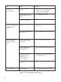
5.3 Troubleshooting
Table 5-2 contains simple troubleshooting procedures which you can follow to
try to restore normal operation. If you cannot restore normal operation, do not
attempt to check inside any unit of the radar system. Any repair work is best
left to a qualified technician.
5.4 Self Test
The self test facility checks the keyboard, ROM and RAM for proper operation.
1. Press the [MENU] key.
2. Select "OTHER MENU".
3. Select "23. Self Test"and press the [ACQ/ENTER] key. The following display appears.
[Self Test]
Key test: Press each key and
check on-screen indication
Lights.
ARPA TEST
RAM
OK
SPEED OK
COURSE OK NAV 0.0KT
TRIGGER NG
VIDEO
NG
BP
OK
HP
OK
MIN-HIT
0003
SCAN-TIME
0854
MAN-ACQ
00
AUTO-ACQ
00
FE-DATA1
0000
FE-DATA2
0000
Program NO:
ROM
:OK
RAM
:OK
Hours in use:000006.9H
Tx hours
:0000001.1H
<Press MENU for OTHERS menu.>
Figure 5-1 Self test screen
41
If...
But...
Then...
you pressed the
[POWER] key to
turn on the radar
the control panel does
not light
try adjusting the control panel
backlighting on the OTHERS menu.
battery may have discharged.
check fuse in power cable.
the radar has warmed
up and you pressed the
[ST-BY/TX] key to
transmit
you have adjusted
the gain with A/C
RAIN and A/C SEA
off
a key is pressed
nothing appears on the
display or display contrast
is poor
try adjusting the brilliance.
characters are distorted
request service.
the antenna does not
rotate
the problem may be in antenna unit.
Request service.
Characters and indications
are abnormal
have a qualified technician check the
set.
neither noise nor targets
appear (indications and
markers do)
check signal cable for damage.
neither indications nor
markers appear (noise
and targets do)
have a qualified technician check the
set.
the sweep (radial line
sweeping around the
display) is not
synchronized with
antenna rotation
the problem may be in the antenna
unit. Request service.
there is no change in
sensitivity
request service.
nothing happens
key may be faulty. Request service.
Table 5-2 Troubleshooting table
42
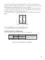
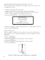
4. The ROM and RAM are automatically checked. If NG (No Good) appears to
the right of ROM or RAM indication, contact your dealer for advice. ARP-10 TEST
results appear only when optional ARP-10 board is mounted.
5. To check the keyboard, press any key except the omnipad, ACQ and power keys
except the omnipad, ACQ and power keys. Its corresponding location on the display lights in black if the key is operating properly.
6. Press the [ACQ] key to check the display circuit. The following pattern should
appear.
Figure 5-2 Test pattern
7. Press the [MENU] key to back to the selftest menu.
8. To escape from the test. Press the [MENU] key.
5.5 Life Expectancy of Magnetron
The following table shows the life expectancy of the magnetron.
Model
Type
MSF1421B
MAF1421B
KR-1668 MAF1421B
KR-1338
Code no.
Life expectancy
V801
2 000 - 3,000 hours
(Including stand-by)
Table 5-3 Life expectancy of magnetron
43
6. INSTALLATION
This chapter provides the procedures necessary for installation.
Installation mainly consists of the following:
sitting and mounting the display unit and antenna unit
connection of the signal cable and the power cable
establishing the ground
checking the installation, and
adjustments.
6.1 Antenna Unit Installation Sitting, handling considerations
The antenna unit is generally installed either on top of the wheelhouse or on
the radar mast on a suitable platform. Locate the antenna unit where there is
a good all-round view rigging intercepting the scanning beam. Any obstruction
will cause shadow and blind sectors. A mast for instance, with a diameter
considerably less than the width of the radiator, will cause only a small blind
sector, but a horizontal spreader or crosstrees in the same horizontal plane as
the antenna unit would be a much more serious obstruction; you would need
to place the antenna unit well above or below it.
It is rarely possible to place the antenna unit where a completely clear view
in all direction is available. Thus, you should determine the angular width
and relative bearing of any shadow sectors for their influence on the radar at
the first opportunity after fitting. (The method of determining blind and
shadow sectors appears later in this chapter.)
If you have a radio direction finder on your boat, local its antenna clear of
the antenna unit, to prevent interference to the direction finder. A separation
of more than two meters is recommended.
To lessen the chance of picking up electrical interference, avoid where
possible routing the signal cable near other onboard electrical equipment
Also avoid running the cable in parallel with power cables.
The compass safe distance should be observed to prevent deviation of the
magnetic compass.
Model
KR-1338
44
Standard compass
0.9m
Steering compass
0.7m
Do not paint the radome (Model KR-1338) or to ensure proper emission of the
radar waves.
When this radar is to be installed on larger vessels, consider the following
points:
(1) The signal cable run between the antenna and the display comes in lengths
of 10 m, 15 m, 20 m and 30 m. Whatever length is used it must be
unbroken; namely, no splicing allowed.
(2) Deposits and fumes from a funnel or other exhaust vent can adversely affect
the aerial performance and hot gases may distort the radiator portion. The
antenna unit must not be mounted where the temperature is more than 70 .
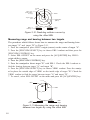
Mounting (KR-1338)
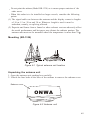
Figure 6-1 Typical antenna unit location
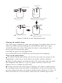
Unpacking the antenna unit
1. Open the antenna unit packing box carefully.
2. Unbolt the four bolts at the base of the radome to remove the radome cover.
Radome cover
ONWA
Figure 6-2 Antenna unit
45
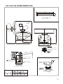
Mounting platform
Holes for antenna unit:
The mounting surface must be parallel with the waterline and provided with four
holes whose dimensions are shown in the outline drawing attached at the end of
this manual. The unit is adjusted so a target echo returned from the bow direction
will be shown on the zero degree (heading line) position on the screen. When
drilling holes, be sure they are parallel with the fore and aft line.
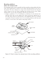
3. Prepare a platform of 5 to 10 millimeters in thickness for the antenna unit.
Find the cable entry on the radome base. Next, position the radome base so
the cable entry faces the stern direction. This alignment must be as accurate
as possible. Fasten the radome base to the mounting platform with four each
of M10 x 30 hex bolts, flat washers and spring washers.
SHIP'S BOW
CABLE
ENTRY
4-
12 HOLES
FLAT WASHER
PLATFORM
SPRING WASHER
HEX BOLT
Antenna base plate
Packing
Effective
thread length
Radome
5 -10 mm
Flat
washer
Spring
washer
Platform
Hex bolt
Apply silicone sealant
Figure 6-3 How to fasten the radome base to the mounting platform
46
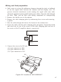
Wiring and final preparation
4. Drill a hole of at least 20 millimeters diameter through the deck or bulkhead
to run the signal cable between the antenna unit and display unit. (To
prevent electrical interference avoid running the signal cable near other
electrical equipment and in parallel with power cables.) Pass the cable through
the hole. Then, seal the hole with sealing compound for waterproofing
5. Remove the shield cover in the radome.
6. Remove the cable clamping plate by unfastening four screws and removing
a gasket.
7. Pass the cable through the hole at the bottom of the radome base.
8. Secure the cable with the cable clamping plate and gasket. Ground the shield
and vinyl wire by one of the screws of the cable clamping plate and one of
the screws of the IF amplifier chassis, respectively.
Motor
If0711
9. Connect the wire to the RF unit.
(1) 9-pin connector to J801
(2) 4-pin connector to J802
(3) 13-pin connector to J611
J801
J802
J611
Figure 6-4 Location of J801/J802/J611
47
11. Fix the shield cover. Do not pinch the cable.
12. Loosely fasten the radome fixing bolts. You will tighten them after
confirming magnetron heater voltage.
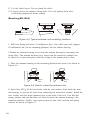
Mounting(KR-1668)
Figure 6-5 Typical antenna unit mounting locations
1. Drill four fixing bolt holes (13 millimeters dia.), One cable entry hole (approx.
50 millimeters dia.) In the mounting platform. See the outline drawing.
2.Detach the antenna housing cover from the antenna housing by loosening four
fixing blots. The antenna housing cover fitted with the transceiver module can
be stored in a convenient place until the wiring to the antenna unit is done.
3. Place the antenna bousing on the mounting platform and orient it as shown in
Figure 6-6.
SHip`s
bow
SHip`s
bow
Figure 6-6 How to orient the antenna unit
4. Insert four M12 60 hex head bolts with the seal washers from inside the antenna housing, to prevent the bolts from contacting the transceiver module. Install the
seal washer with the larger diameter next to the head of the bolt. Coat flat and
spring washers and nuts and then use them to fasten the antenna housing to the
mounting platform. Finally, coat exposed parts of nuts, bolts and flat and spring
washers as shown in Figure 6-7.
48
Note: Tighten the bolts by their nuts to prevent damage to the seal washer.
Do not turn the bolts to secure the antenna housing.
Figure 6-7 How to mount the antenna housing
Connections
Only the signal cable runs from the display unit to the antenna unit. Make the hole
for passing the cable through the bulkhead or deck at least 20 millimeters diameter.
In order to minimize the chance of picking up electrical interference, avoid where
possible routing the signal cable near other onboard electrical equipment. Also,
avoid running the cable in parallel with power cables. Pass the cable through the
hole and apply sealing compound around the hole for waterproofing.
The procedure for connecting the signal cable to the antenna unit is as following.
1. Through a pipe or waterproof cable grand fitted on the wheelhouse top or bulkhead.
2. Unfasten four screws at bottom of the scanner base to remove the cable gland
assembly.
3. Pass the signal cable through the antenna base and the cable gland assembly
(removed in step 2.)
Figure 6-8 Passing the signal cable through the antenna housing
49
4. Fasten the cable gland assembly.
5. Connect the lead wires to CON-0906 in the antenna housing by referring to the
Interconnection Diagram. Fasten the ground washer at the bottom of the antenna
housing as shown in Figure 6-9.
CON-0906
Figure 6-9 Connection in the antenna housing
Final preparation
1. Place the antenna housing cover on the housing, Loosely fasten the four fixing
bolts on the cover.
Figure 6-10 Fastening the antenna housing cover
2. Apply grease to the two slot pins. Using a wooden hammer to prevent damage
to paint, insert slotted pins into the pinning holes until the pin head is flush with
the scanner housing surface.
Figure 6-11 How to insert slot pins
50
3. Now is the time to fix the radiator to the radiator bracket. Apply anticorrosive
sealant (silicone sealant) to hatched areas, to prevent corrosion. See the figure below.
Apply silicone sealant into threaded holes on the scanner radiator. Remove the cap
on the radiator bracket and orient the radiator bracket as shown in Figure 6-12.
Apply grease to the O-ring and set it to the center of the radiator bracket. Coat the
radiator fixing bolts with silicone sealant. Fasten the radiator to the radiator bracket
with the ONWA logo on the radiator facing ship`s bow.
RA12
Figure 6-12 Fastening the radiator to the radiator bracket
4. Open the antenna housing cover and fix the stay as shown in Figure 6-13.
5. One end of the cable with 15-, 9- and 7-way plugs has already been connected
to CON-0906 inside the scanner housing. Mate the 15- and 9-way plugs with jacks
J812 and J811 on the transceiver module, respectively. Connect the 7-way plug to
jack J801 on the MOD Board. Secure the cable between CON-0906 and J801 with
the cable tie as shown in Figure 6-13.
Figure 6-13 Antenna unit, cover opened
51
6. Fasten the ground wire (black) of the signal cable to the chassis as shown in
Figure 6-13.
7. Loosely fasten the antenna housing cover. You will tighten the fixing bolts after
confirming magnetron heater voltage.
6.2 Display Unit Installation Mounting considerations
When selecting a mounting location for the display unit keep in mind the
following points.
Even though the display unit is waterproof, it is recommended that the
display unit must be mounted inside an enchosed cabinet.
Provide adequate space behind and around the unit to permit circulation of
air and to provide convenient access to the rear connectors.
Even though the picture is quite legible even in bright sunlight, keep the
display unit out of direct sunlight or at least shaded because of heat that can
build up inside the cabinet.
Locate the display unit in a position where you can view and operate it
conveniently but where there is no danger of salt or fresh water spray or
immersion.
The orientation of the display unit should be so the radar screen is viewed
while the operator is facing in the direction of the bow. This makes
determination of your position much easier.
Make sure you allow enough clearance both to get to the connectors behind
the unit and to allow you to get your hands in on both sides to loosen or
tighten the mounting knobs. Make sure you leave at least a foot or so of
"service loop" of cables behind the unit so it can be pulled forward for
servicing or easy removal of the connectors.
The compass safe distance of 0.8 meters (standard compass) and 0.6 meters
(steering compass) should be observed to prevent deviation of the magnetic
compass.
Mounting
The display unit is designed to be mounted on a tabletop or bulkhead.
1. Using the hangar as a template, mark screw locations in the mounting location.
2. Fix the hanger to the mounting location with four M6 tapping screws(supplied).
3. Fit the knob bolts to the display unit. Install the display unit in the hunger.
Tighten the knob bolts securely.
52
Connections
1. Connect the power cable to the power cable connector on the rear of the
display unit.
2. Connect the signal cable to connector on the rear of the display unit.
3. Run a ground wire (local supply) between the ground terminal on the rear
of the display unit and the ship's superstructure.
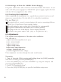
Navigation aid, video sounder connection
If your navigation aid can output data in IEC1162(NMEA 0183) data format, your
vessel's position in latitude and longitude, the range and bearing to waypoint, speed and course may be input to this radar, and be seen on the screen.
Further if your video sounder can output depth in IEC 1162(NMEA 0183) data format, depth can be displayed on the radar screen.
NMEA-1 connector:
1)+3.3V 2)NMEA Input 1 3)NMEA Output 1 4)GND 5)GND 6)SPARE
NMEA-2 connector:
1)+3.3V 2)NMEA Input 2 3)NMEA Output 2 4)GND
5)NMEA Input 3 6)NMEA Output 3 7)GND 8)GND
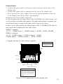
4. Upgrade interface for radar software upgrades.
CAUTION
Replace the fuses to 5
A for 24/32 VDC set.
GND
Option
Power
GND
Fuse Holder
Upgrade
NMEA-1 Connector
NMEA-2 Connector
CAUTION
Ground the equipment.
Ungrounded equipment can give
off or receive electro-magnetic
interference or give electrical
shock.
Figure 6-14 Connections on the display unit
53
6.3 Exchange of Fuse for 24/32V Power Supply
The power cable comes with a 10A fuse in the fuse holder. This fuse is for use
with a 12V DC power supply. For 24V/32V DC power supply, replace the fuse
with the 5A fuse (supplied) to fuse holder.
6.4 Checking the Installation
After completing the installation, it is a good idea to recheck it to be sure all
steps were correctly done. Use the table 6-1 to check the installation.
Tick box (Table 6-1)
The signal cable is securely retained against the mast or mounting platform
and is free of interference from running rigging.
The
The
The
The
cable gland or entry on the deck, if provided, is waterproofed.
power connections to the battery are of correct polarity.
plugs at the rear of the display unit are tightly fastened.
fuse in the power cable is 10A (12V) or 5A (24V/32V DC).
6.5 Adjustments
This section covers adjustment of the radar after installation.
You will need to
adjust tune/video amplifier level input
enter antenna height
adjust tuning level
adjust sweep timing
adjust main bang suppression
setting a blanking area, and
confirm magnetron heater voltage.
These adjustment are done through the radar install menus.
Preparation
1. Turn off the radar. While pressing and holding down the [GAIN] control(at
least three seconds), press the [POWER] key.
2. Press the [MENU] key, and select "OTHERS" by using the omnipad, and
pressing [ACQ/ENTER] key.
3. Select "24. Installation setup".
4. Press the [ACQ/ENTER] key to open the installation setup menu.
54
[ Installation Setup]
Select item by omnipad
and ress ENTER key.
1. Nav Talker
All
2. Depth Unit
m
3. Temp Unit
4. Hdg Sensor
Magnet
5. Key Beep
Off
6. Ant on Tx
Rotate
7. Dead Sector
180 ~180
8. Tuned/Video Auto Adjustment
9. Heading Alignment
10. Sweep Timing Adjustment
11. MBS Adjustment
12. Ant Height
Low
13. STC Curve
Sharp
14. Ope Mode
Master
15. Hours in Use
000001.5H
16. Tx Hours
000000.0H
GPS
fa
F
Gyro
On
Stop
Mid
Std
Slave
LC
ft
Hig
Gntl
Figure 6-15 Installation setup ment
Adjusting tune/video
Do the following to adjust tune and video amplifier level input.
1. Press the [ST BY/TX] key to transmit.
WARNING
Before transmitting the radar make sure no one is near
the antenna unit, to prevent the potential risk of being
struck by the rotation antenna and exposure to Therefore
radiation hazard.
2. On the Installation setup menu, select "8.Tune/Video Adjustment" and press the
[ACQ/ENTER] key.
3. The unit automatically adjusts, displaying the following message.
[Tune/Video Auto Adjustment]
Now under correction.
Return to installation setup
menu after the correction.
Figure 6-16 Tune/Video Auto Adjustment messages
4. When adjustment is completed, the messages disappears.
55
Entering antenna height
The STC curve changes with respect to antenna height above the waterline. Enter
antenna height above the waterline to optimize the STC curve.
1. Select "12.Antenna Height" on the installation setup menu and press the [ACQ/
ENTER] key.
2. Operate the omnipad to select antenna height above the waterine; Low (~3 m),
Mid (3~6m) or High (6~10 m).
3. Press the [ACQ/ENTER] key.
Aligning heading (Adjustment sector:0~359.90)
You have mounted the antenna unit facing straight ahead in the direction of the
how. Therefore, a small but conspicuous target dead ahead visually should appear
on the heading line (zero degrees).
In practice, you will probably observe some small error on the display because of
the difficulty in achieving accurate initial positioning of the antenna unit. The following adjustment will compensate for this error.
1. Identify a suitable target (for example, ship or buoy) at a range between 0.125
to 0.25 nautical miles, preferably near the heading mark. To lessen error, keep echoes in the outer half of the picture by changing the range. Aiso, be sure the zoom
and off center functions are off.
2. Select "9. Heading Alignment" on the installation setup menu and press the
[ACQ/ENTER] key. The following message appears on the display.
[ Heading alignment ]
Set EBL1 to center of target
dead ahead and press ENTER.
Correction
0.0
<Press MENU for inst setup>
Figure 6-17 Heading alignment message
3. Operate the omnipad to bisect target selected at step 1 with the heading line.
4. Press the [ACQ/ENTER] key.
5. As a final test, move the boat towards a small buoy and confirm that the buoy
shows up dead ahead on the radar when it is visually dead ahead.
56
Adjusting sweep timing(Adjustment range:0.000~4.266nm)
This adjustment ensures proper radar performance, especially on short ranges.
The radar measures the time required for a transmitted echo appears on the
display based on this time. Thus, at the instant the transmitter is fired, the
sweep should start from the center of the display (sometimes called sweep
origin.) A trigger pulse generated in the display unit goes to the antenna unit
through the signal cable to trigger the transmitter (magnetron). The time taken
by the signal to travel up to the antenna unit varies, depending largely on the
length of signal cable. During this period the display unit should wait before
starting the sweep. When the display unit is not adjusted correctly, the echoes
from a straight local object (for example, a harbor wall or straight pier) will
not appear with straight edges - namely, they will be seen as "pushed out" or
"pulled in" near the picture center. The range of objects will also be incorrectly
shown.
(1) Correct
(2) Target pushed
inward
(3) Target pushed
outward
Figure 6-18 Examples of improper and correct sweep timing
1. Transmit on the shortest range and confirm that the [GAIN] and [STC]
controls are properly adjusted.
2. Visually select a target which forms straight line (harbor wall, straight pier).
3. Select "10.Sweep Timing Adjustment " on the installation setup menu and
press the [ACQ/ENTER] key. The message appears.
[ Sweep Timing Adjustment ]
Use omnipad to staighten
Target and press ENTER key.
Correction
0.000 nm
<Press MENU for inst setup>
Figure 6-19 Sweep timing adjustment message
4. Operate the omnipad to straighten the target selected at step 2, and then press
the [ACQ/ENTER] key.
57
Adjusting MBS (Main Ban Suppression)(Adjustment: 0.00~0.25)
Main bang (black hole), which appears at the display center on short ranges, can
be suppressed as follows.
1.
2.
3.
4.
5.
Transmit on long range about 10 minutes.
Adjust the gain to show a small amount of noise on the display.
Change to the 0.125 nautical mile range and adjust the [A/C SEA] control.
Select "11.MBS adjustment" on the installation setup menu.
Press the [ACQ/ENTER] key. The following message appears.
[MBS Adjustment ]
Set value by omnipad
and press ENTER key
Correction
000
<Press MENU for inst setup>
Figure 6-20 MBS Adjustment message
6. Operate the omnipad to suppress main bang.(Left: low, right, between 0 and 25)
7. Press the [ACQ/ENTER] key.
Setting a blanking area]
When the antenna is installed at a close distance in front of the wheelhouse, the
radar should be set not to transmit within that area. No echoes appear in the blanking areas.
1. Select "7.Dead Sector".
2. Press the [ENTER] key.
3. Operate the omnipad to enter staring point of area (in figures).
4. Press the [ENTER] key.
5. Operate the omnipad to enter ending point of area (in figures).
6. Press the [ENTER] key,
Area of no
transmission
Figure 6-21 Blank areas where transmission is suspended
58
This area can be turned on/off on the OTHER MENU. For detail, see the description on page 18.
Note: This setting should be done after other adjustment are finished.
Magnetron heater voltage
Magnetron heater voltage is formed at the MOD Board of the antenna unit and preadjusted at the factory for use with any length of signal cable. Therefore no adjustment is required. However, verify heater voltage by following the procedure
below.
1. Turn on the radar(if it is not already on) and set it in stand-by.
2. Open the antenna housing (radome) cover. Connect a multitester, set to 10V DC
range.
Model
Check point
Rating
Adjustment
Point
KR-1338 Tp803 #4,#6
7.4~7.6V VR801
on MD Borad
7.4~7.6V VR801
KR-1668 Tp803 #4,#6
on MD Borad
3. Close the antenna housing cover and tighten the fixing bolts.
59
MENU TREE
MENU KEY
RINGS(Off,1,2,3,max)
EBL OFFSET Off On
SHIFT Off On
ZOOM Off On
MODE HU CU NU TM
DISP DATA
ECHO TRAIL Off On
ECHO STRTCH Off ES 1
ARPA MENU
OTHER MENU
ES2
1 .Display
2 .AllCancel
3 .Vectpr ref
4 .Vector Length
5 .History
6 .CPA SET
7 .TCPA SET
8 .AUTO ACQ
1 .Panel Dimmer 1,2,3,4
2 .Mark Brill 1,2,3,4
3 .HD Mark 1,2,3,4
4 .Characters 1,2,3,4
5 .Trail Tone Single Multi
6 .Int Reject Off 1,2,3
7 .Pulselength Short Long
8 .Noise Reject Off On
9 .Trail Time
15S 30S 1M 3M 6M 15M 30M Cont
10 .Tone Auto Manu
11 .Disp Data Off Nav ARP All
12 .WPT Mark Off On
13 .EBL Ref Rel True
14 .VRM Unit nm km sm
15 .Watchman Off 5M 10M 20M
16 .STBY DISP Norm Econo Nav
17 .Guard Mode In Out
18 .Cursor Posi B/R,L/L
19.Alm Sense LV Low Mid High
36):1016
20 .Dead Sector Off On
36,48):1048
21 .Range
1/8 1/4 1/2 3/4 1 1.5/2 3 4 6 8 12 16 24, 36,48,64):1064
22.Color Setting
23.Self Test
24.Installation Setup
1 .Nav Talker All GPS
2 .Depth unit m fa ft
3 .Temp Unit
C, F)
4 .Hdg Sensor(Magnet,Gyro)
5 .Key Beep Off On
6 .Scan Stop Rotate Stop
7 .Dead Sector
8 .Tune/Video Adjustment
9 .Heading Alignment
10 .Sweep Timing Adjustment
11 .MBS Adjustment
12 .Ant Height Low Mid High
13 .STC Curve(Sharp,std Gntl)
14 .Ope Mode Master Slave
15 .Hours in Use
16 .TX Hours
60
ARPA
WARNING
This auto plotter is not designed to replace the human eye nor make decisions for the navigator. It is intended for use as an aid to navigation. Always maintain a watch while underway.
Data obtained from this auto plotter should always be double checked against other sources
to verify the reliability of the data.
This auto Plotter automatically tracks a acquired radar target and calculates its course and speed.
Indicating it by a vector, Since the data generated by this unit are based on what radar targets are
selected, the radar must always be optimally tuned for use with it to ensure that required targets
will not be lost or unwanted targets such as sea returns and noise will not be acquired and tracked.
A target echo does not always mean a landmass, reef, ships or other surface objects but can imply
returns from sea surface or precipitation. As the level of these returns varies with environment, the
operator is required to properly adjust the STC (ant-clutter sea), FTC (anti-clutter rain) and GAIN
controls to ensure that target echoes within the affected area are not eliminated from the radar screen.
The optimum settings of these controls may slightly differ between the normal radar operation and
plotting, and it is recommended to readjust them in accordance with the operating mode selected.
NOTICE
The installation must be done by a ONWA representative or suitably qualified radar technician.
Authorities require this.
Keep magnets and magnetic fields away from the equipment.
Magnetic fields will distort the picture and can cause equipment malfunction. Be sure the unit is well
away from equipment which gives off magnetic fields (speaker, power transformer, etc.).
The following items affect calculation accurary.
echo intensity
radar transmission pulsewidth
radar bearing error
gyrocompass error
own vessel or other vessel course change
Data for CPA, TCPA, ect. Are approximations only. Always use data obtained prudently.
61
Operation of ARPA
General
The Auto Plotter permits manual or automatic acquisition and automatic tracking
of up to 10 radar targets. An internal microprocessor calculates target data such as
speeds and courses and display the results in alphanumeric and by vectors. To ensure the reliability of the displayed target data, the radar must be properly adjusted for minimum sea returns and noise.
Principal Specifications
Acquisition and tracking:
Acquisition of up to 10 targets between 0.2 and 16 nm.
Automatic tracking of up to 10 acquired targets between 0.1 and 16 nm.
Vectors:
Vector length; 30s, 1,3,6,15,30 min.
Orientation; True velocity or relative velocity
Past positions: 5 past positions at intervals of 15,30s,1,2,3,6 min.
Alarm: Visual and audible alarms against targets violating CPA/TCPA limits,
Visual alarm against lost targets
Target discrimination: A target measuring about 800 m or more in the radial or
circumferential direction is regarded as a landmass and not acquired or tracked.
Echoes smaller than about 800 m are regarded as true targets.
Key Used Auto Plotter
The Auto plotter utilizes the following touchpad keys. Given below is a brief description of these keys.
MENU: Display/Eraese the main menu.
SELECT/CANCEL:
(Long press) Terminates plotting of the target selected with the cursor.
(Brief press) Displays the data of target selected with the cursor.
ACQ/ENTER: Acquires the target selected with the cursor.
62
ARPA MENU Operation
The ARPA MENU operation includes the followings;
Display: Turns on/off the plot symbols, past positions and target data.
All Cancel: Cancels the tracking of all targets.
Vector Ref: Selects relative vector or true vectors. To select your choice, open
the ARPA menu, and the legend Rel and True appear on the "3. Vector Ref"
line. Operate the omnipad. When your selection is in the reverse video, press the
[ACQ/ENTER] key.
Vector Length: Selects vector time.
History: Selects past position plot interval.
CPA Set: Selects CPA alarm limit, When a target is predicted to come within
this limit, an aural alarm sounds and at the same time the corresponding target
symbol changes to a blinking triangle.
Note: If the preset CPA limit is set at OFF, a target which is on collision course
will not produce an alarm.
TCPA Set: Selects TCPA alarm limit.
Auto ACQ: Turns on/off Auto Acquisition Area.
Activating the Auto plotter
To activate the Auto Plotter, follow the steps shown below:
1. Adjust the GAIN, A/C SEA and A/C RAIN controls for proper radar picture.
2. Press the [MENU] key to open the main menu.
3. Operate the omnipad to select "ARP-10 MENU".
4. Press the [ACQ/ENTER] key. The menu shown in Figure AP-1 appears.
5. Operate the omnipad to select the menu item "1. Display".
6. Operate the omnipad to select "On".
7. Press the [ACQ/ENTER] key.
8. Press the [MENU] key to close the menu.
63
[ARPA MENU]
Select item by omnipad
and press ENTER key
1. Display
2. All Cancel
3. Vector Ref
4. Vector Length
Off
On
Ref
True
30s
15M
30s
6M
1nm
6nm
2M
6M
On
3M
Off
2M
Off
3nm
30s
4M
Off
5. History
6. CPA Set
7. TCPA Set
8. Auto ACQ
6M
15s
3M
0.5
5nm
1M
5M
1M
30M
1M
2nm
3M
12M
Figure AP-1 ARP Menu
Target under auto tracking but not
selected for cursor data reading
125NM
Target Full
Mark
HDG 234.5
AUTO
TRAIL
25:38 30M
G(OUT)
ZOOM
ES1
*
2 AUTO TARGET
FULL
SP
HU
Target selected
for data reading
Auto
Acquisition
Area
Lost Target
Threatening
target
A/C
AUTO
EBL
345.6 R
23.0 R
Own SHIP
34 56.12N
135 34.56E
SPD 35.OKT
1.5 HM
13.5 R
0.06
0.142HM
+ CURSOR
34 29.38N
136 35.77E
TTG 01:00
VRM
0.048NM
0.100NM
WAYP OINT
0.09 NM
50.0 M
TTG 00:20
Figure AP-2 ARPA Display
64
Deactivation the Auto Plotter
To deactivate the Auto Plotter.
1. Open the "ARPA MENU".
2. Operate the omnipad to select the "1. Display".
3. Operate the omnipad to select "Off".
4. Press the [ACQ/ENTER] key.
5. Press the [MENU] key to close the menu.
Acquiring targets
Manual Acquisition
Follow the steps below to manually acquire a target. Up to 10 target can be manually acquired.
1. Place the cursor(+) on a target of interest by operating the omnipad.
2. Press the [ACQ/ENTER] key.
The plot symbol changes its shape according to the status as below. A vector appears in about one minute after acquisition indicating the target's motion trend. If
the target is consistently detected for three minutes, the plot symbol changes to a
solid mark. If acquisition fails, the target symbol blinks ans disappears shortly.
SQUARE (dotted)
Immediately after acquisition - Plot symbol shown in broken lines.
SQUARE(dotted with a vector)
One minute after acquisition - Vector still unreliable.
CIRCLE(Soild with a vector)
3 minutes after acquisition - Plot symbol changes to a solid circel indicating
the stable tracking condition.
LARGE CIRCLE
The plot symbol of a target under tracking becomes twice as large as the normal symbol when the target is selected for data reading.
Note 1: The target to be acquired should be within 0.2 to 16 nm from own
ship and not obscured by sea or rain clutter for successful acquisition.
Note 2: When you want to acquire 11th target, cancel tracking one of less important target.
65
Note 3: When auto acquisition mode (Auto ACQ) is on, up to 5 target can be acquired. For detail, see next section titled Automatic Acquisition.
WARNING
When a tracked target nears another tracked target the
targets may be "swapped."When two target come
close to each other, one of the two can become a "lost
targets."Should this happen, reacquisition of the "lost
target"is required after the two targets have separated.
Automatic Acquisition
The Auto plotter APRA can acquire up to 5 targets automatically by setting the
Auto Ac-quisition area predefined in the system. If Auto ACQ is selected after
more than 5 targets have been manually acquired, only the remaining capacity of
targets can be automatically acquired. Example; when 7 targets acquired manually,
then the Auto ACQ is switched on only 3 targets can be acquire automatically,
When five targets have been automatically acquired, "AUTO TARGET FULL"
message appears at top left corner on the display.
Setting Auto Acquisition Area
Auto acquisition area is predefined between 2.0 and 2.5 nm in range and 45 on
either side of the heading line in bearing. If a target come into this area, it is acquired automatically.
Figure AP-3 Auto acquisition area
Follow the steps shown below to activate the auto acquisition area;
1. Open the "ARPA MENU".
2. Select "8. Auto ACQ"by operating the omnipad.
3. Operate the omnipad to select "On".
4. Press the [ACQ/ENTER] key.
5. Press the [MENU] key to close the menu.
66
Terminating Tracking of Targets
When the Auto Plotter has acquired 10 targets, no more acquisition occurs unless
targets are lost. Should this happen, cancel tracking of individual target or all targets by the procedure described below.
Individual Targets
Place the cursor (+) on a target which you do not want to be tracked any longer
by operating the omnipad and press andgold down the [SELECT/CANCEL] key.
All Targets
All targets can be canceled from "ARPA MENU"at a time.
1. Open the "ARPA MENU".
2. Select "2.All Cancel".
3. Press the [ACQ/ENTER] key.
Displaying Target Data
The Auto Plotter calculates motion trends (range, bearing, course, speed, CPA and
TCPA) of all targets under tracking at the ARP Data area.
To turn ARP data on;
1. Press the [MENU] key.
2. Select the "DISP DATA".
3. Press the [ACQ/ENTER] key to select the message for "ARP""NAV and
ARP".
4. Press the [ACQ?ENTER] key to set.
5. Press the [MENU] key to close the menu.
CAUTION
At the speed under 5 kts the target data is
displayed with a delay because of the filtration
Place the cursor on a wanted target and press the [SELECT/CANCEL] key. Data
on the selected target is displayed at the bottom of the screen. The symbol of the
selected target gets twice as large as the normal circle. The data includes the
follows;
RNG/RBG (Range/Bearing): Range and bearing from own ship to the last-plotted
or selected target position with suffix"T"(Ture) or "M"(Magnetic). For ture
bearings suffix "T"is used in case of gyrocompass input and suffix "M"is
used in case of magnetic compass input.
67
COURSE/SPEED (Course/Speed):
Course and speed are displayed for the lastplotted or selected target with suffix
"T"(Ture) or "M"(Magnetic). For true bearings suffix "T"is used in case
of gyrocompass input and suffix "M"is used in case of magnetic compass input.
CPA (Closest Point of Approach) is the closest range a target will approach to own
ship. Do not mix it with the operator preset CPA alarm limit.
TCPA is the time to CPA measured with present speeds of own ship and the targets.
Both CPA and TCPA are automatically calculated. When a target ship has passed
clear of own shop, the CPA is displayed and the TCPA appears as "**". TCPA
is counted up to 99.9 min. And beyond this it is indicated as TCPA>99.9 min.
Mode and length of Vectors
Ture or Relative Vector
Target vectors are displayed in relative or true mode. Own shop does not have a
vector in relative mode.
Vector Length
From the ARPA MENU, Vector Length can be set to 30 seconds,1,3,6,15 or 30
minutes and the selected vector time is indicated on the screen.
The vector tip shows an estimated position of the target after the selected vector
time elapses. It can be valuable to extend the vector length to evaluate the risk of
collision with any target.
Past position Display
The Auto Plotter displays equally time-spaced dots(maximum 5 dots) marking the
past positions of any targets being tracked.
If a target changes its speed, the spacing will be uneven. If it changes the course,
its plotted course will not be a straight line in TM mode.
Operational Warnings
There are two main situations which cause the Auto plotter to trigger visual and
audible alarms.
CPA/TCPA alarm
Lost target alarm
68
CPA/TCPA Alarm
Visual and audible alarm are generated when the predicted CPA and TCPA of any
target become less than their preset limits. The audible alarm continues for 10 seconds.
The Auto plotter ARPA continuously monitors the predicted range at the Closest
Point of Approach(CPA) and predicted time to CPA(TCPA) of each tracked target
to own ship.
When the predicted CPA of any target becomes smaller than a preset CPA alarm
range and its predicted TCPA less than a preset TCPA alarm limit, the ARPA
releases an audible alarm. In addition, the target plot symbol changes to a triangle
and flashes together with its vector.
Provided that this feature is used correctly, it will help prevent the risk of collision
by alerting you to threatening targets, It is important that GAIN, A/C SEA, A/C
RAIN and other radar controls are properly adjusted and the Auto Plotter is set up
so that it can track targets effectively.
CPA/TCPA alarm ranges must be set up properly taking into consideration the size,
tonnage, speed, turning performance and other characteristics of own ship.
WARNING
The CPA/TCPA alarm feature should never be relied
upon as a sole means for detecting the risk of collision.
The navigator is not relieved of the responsibility to keep
visual lookout for avoiding collisions, whether or not the
radar or other plotting aid is in use.
Follow the steps shown below to set the CPA/TCPA alarm ranges:
1. Open the "ARPA MENU".
2. On the "CPA Set"line, select a CPA limit desired.(Off,0.5,1,2,3,5,6nm)
3. Press the [ACQ/ENTER] key.
4. On the "TCPA Set"line, select a TCPA limit desired.(30s,1,2,3,4,5,6,12M)
5. Press the (ACQ/ENTER] key.
6. Press the [MENU] key to close the menu.
69
The flashing of the triangle plot symbol and vector remain on the screen until the
dangerous situation is no longer present or you intentionally terminate tracking of
the target by using the [SELECT/CANCEL] key.
Lost Target Alarm
When the system detects a loss of a tracked target, the target symbol becomes a
flashing diamond.
70
130.5
276.8
148
276
27.5
74
276.8
65
40
276
286
150
6
140
310
71
ONWA
Antenna base plate
Packing
Effective
thread length
Radome
5 -10 mm
Flat
washer
Spring
washer
Apply silicone sealant
72
Platform
Hex bolt
KR-1338/1668 INTERCONNECTION
124
1250
RA12
RADIATOR S=1/25
RA12: KR-1668
FORWARO
440
585
RA12
185
240
260
240
635
350
M12 BOLT
SEAL WASHER CW10530X
PLATFORM
F.W .
168
140
240
8) )
(X N
A
5 4 0 (X N 1 2
650
D
F
IA.O
ROT
ATI
S.W
M12 NUT
ON
CENTER OF ROTSTION
13
FIXING HOLES
30
45
150
50
CABLE ENTRY
178
185
MOUNTING DIMEENSIONS
73
TO DISPLAY UNIT
TO DISPLAY UNIT
TO DISPLAY UNIT
+12V
+12V
GND
-12V
-12V
TX TRIG
P/L A
P/L B
BEARING
MOTOR(+)
HEADING
MOTOR(-)
-12V
+12V
GND
MIBS SIG
B.W
MIBS SIG
-12V
+12V
GND
B.W
TUNING IND
GND
MIBS L
GND
VIDEO
TUNING
MOD 0904
J801
1
2
3
4
5
6
7
8
9
J802
1
2
3
4
J804
1
2
3
4
5
6
7
8
IF 0711
J613
1
2
3
4
5
6
7
8
J611
1
2
3
4
5
6
7
8
9
10
11
12
13
MDD UNIT
IF UNIT
J612
P1
6
5
4
3
2
1
4
3
2
1
TP803
1
2
3
4
5
6
J803
1
2
3
4
5
J805
1
2
3
TD801
TD802
+5V
GND
TUNE
IF
TX-HV
+15V
+7.5V
MIG Current
GND
+12V
ENGODER
GND
HEADING
HEADING
COLD
(YELLOW)
HOT
(GREEN)
KR-1688 ONLY
KR-1338 ONLY
TUNE
+5V
IF
GND
S801
NRS-101
M801
Kg
BOM-ZYW-40/01 A-01
2009.07.30
MASS
MARTIN
MIC
NJT1668
1
2
3
4
DRAWN
CHECKED
APROVED
SCALE
Data
V801
FCX73
HY801
1 of 1
A3
Rev
SCANNER CONNECT
SCANNER UNIT INTERCONNECTION
SCHEMATIC DIAGRAM
EXPRESS COMMUNICATION & NAVIGATION COMPANY LTD.
ORGANIZATION
TYPE
NAME
DRW NO
TO ANTENNA
MA1421 or MSF1421
2.0
KR-1338/1668
MODEL
Size
Sheet
74
GPS
1
2
3
4
5
6
+3.3V
GPS IN
NMEA OUT1
GND
+3.3V
GYRO IN
NMEA OUT2
GND
KEY 0912
P8
P9
1
2
3
4
5
6
7
8
9
10
11
DISPLAY UNIT
P4
1
2
3
4
P3
1
2
3
4
P2
1
2
3
4
1
2
3
4
5
6
7
8
9
10
DCPWR
DC+
+5V
+12V
-12V
-32V
GAIN
AC-SEA
AC-RAIN
GND
ECONOMY
PNL-BOZZ
PNL-DIM
MIAN TUN
GND
VDD3.3V
GND
WARNING
HP
BP
P0 3
RX-data
RST
GND
MAIN 0804
P53
1
2
3
4
5
6
7
8
9
10
11
P59
1
2
3
4
5
6
7
8
9
10
P8
1
2
3
4
MHDR1X4
P56
LCD
P10
P57
CN1
LCD Display
MAIN UNIT
P52
J1
GND
VIDEO SIG
BP
HD
TX-TRIG
P/L-B
P/L-A
TUNIND
TUNING
GND
TO SCANNER UNIT
P60
P51
1
2
3
4
5
6
7
8
1
2
3
4
5
6
7
8
9
10
11
GND
HEADING
GND
BEARING
GND
TRIG
GND
OP-VIDEO
+32V
+12V
+5V
GND
GND
-12V
DCPWR
DC+
ANT.SW
Kg
TO SLAVE
MOTOR(+)
MOTOR(-)
+32V
+12V
+12V
+5V
GND
GND
-12V
-12V
ANT.SW
GND
PWR
DC+
DC-
TO SCANNER UNIT
+12V
GND
EXT-BUZZER
1 of 1
A3
Rev
2.0
KR-1338/1668
MODEL
Size
Sheet
FIL 0912
P1
X1
FILTER BOARD
PWR 0912
P1302
J1301
POWER BOARD
DISPLAY UNIT
SCANNER UNIT INTERCONNECTION
SCHEMATIC DIAGRAM
EXPRESS COMMUNICATION & NAVIGATION COMPANY LTD.
ORGANIZATION
TYPE
NAME
DRW NO
MHDR1X15
1
2
3
4
5
6
7
8
9
10
11
12
13
14
15
SHIP`S MAINS +
SHIP`S MAINS -
1
2
1
2
3
4
+
+
-
MAINS
MAINS
MAINS
MAINS
SHIP`S
SHIP`S
SHIP`S
SHIP`S
1
2
3
4
GND
TO EXT. ALARM
DRAWN
2009.12.15
MASS
MARTIN
CHECKED
APROVED
SCALE
Data
MOTOR(+)
MOTOR(-)
+12V
GND
-12V
LCD DATA BUS
14
13
12
11
10
9
8
7
6
5
4
3
2
1
BL-12V
3
2
1
3
2
1
ECHO & GYRO
1
2
3
4
5
6
7
8
ECHO IN
NMEA OUT3
GND
KEYPAD UNIT
P1
1
2
3
4
5
4
3
2
1
75
GND
H-SYNC
VIDEO
V-SYNC
GND
MBS SIG
76
X1
SHIP`S MAINS +
SHIP`S MAINS -
1
2
KRC-003-10/15/20
HEADING/DEPTH DATA
4
IN
5
OUT3 6
7
8
TUNING IND
MBS_L
SLAVE DISPLAY
1
2
3
4
5
6
7
8
GND
VIDEO
TUNING
KRA-1002
GND
P60
GND
HEADING
GND
BEARING
GND
TRIG
GND
OP-VIDEO
1
2
3
4
5
6
7
8
9
10
11
12
13
IF 0711
(NMEA0183)
1
IN
OUT2 23
1
2
3
4
ANTENNA UNIT
NMEA-2
ECHO & GYRO
+3.3V
GYRO
NMEA
GND
ECHO
NMEA
GND
GND
BEARING
MOTOR (+)
HEADING
MOTOR (-)
1
2
3
4
5
6
7
8
9
J802
1
2
3
4
5
6
KRD-1002
NAV/HEADING/DEPTH DATA
(NMEA0183)
DISPLAY UNIT
NMEA-1
GPS
1
2
3
4
5
6
7
8
9
10
11
12
13
14
15
16
17
18
19
20
A
B
C
+12V
+12V
GND
-12V
-12V
TX TRIG
P/L A
P/L B
J801
DJ1
+3.3V
GPS IN
NMEA OUT1
GND
GND
MOD 0904
12/24/32VDC
P56
GND
H-SYNC
VIDEO
V-SYNC
GND
1
2
3
4
5
P57
TO EXT. BUZZER
+12V
GND
EXT-BUZZER
1
2
3
MAIN 0804
DRAWN
MASS
2009.07.30
MARTIN
CHECKED
APROVED
SCALE
Data
Kg
MODEL
Size
Sheet
Rev
KR-1338
A3
1 of 1
2.0
DRW NO
NAME
TYPE
C1338-001
INTERCONNECTION DIAGRAM
SCHEMATIC DIAGRAM
EXPRESS COMMUNICATION & NAVIGATION COMPANY LTD.
ORGANIZATION
77
KR-1338/1668
78