Transcript
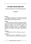
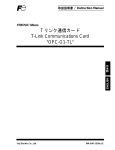
PSZ012D026AL
Superlink WEB Gateway SC-WGWNA-B Installation Manual
● Please be sure to read this manual carefully and follow it before installation work.
Caution: After connecting wires as shown, fasten the terminal safety covers.
● Please refer to indoor unit and outdoor unit installation manual together for installation work.
● Please be sure to use round crimped terminals (N2-4(JST) or equivalents) when connecting wires to the power supply terminal block.
● The appliance must be installed in accordance with national wiring regulations.
● The product is precision equipment, so please handle it with enough care to prevent the unit damage due to falling and being stepped on.
● Before touching the terminal block, turn off the power supply.
● Please do not turn on the power supply until all of the work is completed.
● Please wait at least two minutes after the indoor and outdoor units are turned on before turning on the power supply.
Safety Precautions
Superlink signal line
● Please read this “Safety Precautions” for installation work and follow it properly.
2
2
Shielded wire(double-core, 0.75mm ∼1.25 mm ).
Max. 1000m per line (Max. distance: 1000m, Total wire length: 1000m)
● Safety Precautions are divided into “Warning
“ and “Caution
”.
WARNING: Wrong installations may cause serious consequences such as serious injuries or death.
CAUTION : Wrong installations may cause serious consequences depending on circumstances.
Please be sure to follow the instruction.
After the installation, please make a test run and confirm no abnormalities occurs during the test run.
Please explain the operation method to the customers according to the user’s manual.
Please request the customers to keep this installation manual.
Note 1: When this Gateway is used, use a shielded wire for the Super Link signal wire. Ground both ends of the shielded wire.
(Please wire the ground of the Gateway at
Ground position.)
Note 2: If the indoor and outdoor units connected to the network are all compatible units with New Super Link, a total wire length of 1500m per
2
line is possible (maximum distance: 1000m). However, be sure to use a 0.75mm wire diameter if the total wire length exceeds 1000m.
For further information, please contact your sales representative or dealer.
Note 3: Please be sure to use round crimped terminals (N1.25-3(JST) or equivalents) when connecting wires to the Superlink terminal block.
Ethernet signal line
WARNING
● Please consign the installation work to the dealer or professional installer. Self-installation may cause incomplete work, electric shock and
resultant fire.
● Please install the unit properly according to the installation manual. Incomplete installation may cause electric shock and resultant fire.
● Please be sure to only use attached accessories and specified parts for the installation work, or it may cause electric shock and resultant
fire.
Use the 10BASE-T or 100BASE-TX Twisted pair cable.
Pulse Input line
2
Size: 0.75 ∼ 1.25mm
Maximum extension length: 200m or less per 1 pulse input line.
Type: VCTF(2 cores), CPEV(2 cores)
● The electrical work should be performed by qualified electrical engineer, according to <Electrical Standards>, <Local electrical safety
regulations> and wiring specification. Incomplete installation work may cause electric shock and resultant fire.
3. Installation work
● When wiring, ensure solid connection and fasten specified cables securely so that terminal connections may not be subject to external
force working on cables. Incomplete connection for terminal wiring may cause electric shock and resultant fire.
CAUTION
● Please perform grounding work.
Please do not connect the ground wire with gas pipes, water pipes, lightning rod and telephone ground wire. Incomplete grounding work
may cause the electric shock.
3.1 Installation place
The installation place should be indoor cool place with enough cooling air circulation. The ambient temperature
should be less than 40 degrees Celsius.
Choose the installation place inside a metal enclosure with locked doors preventing persons from
touching the power line terminal on the front surface of the main body.
3.2 Locally procured parts
Before installing the product, prepare the following parts.
Main body installing screws M4 × 4 pieces
● Please do not install the central control at the following places.
1. Oil fog filled place, oil spraying and steamy location such as kitchen, etc.
2. The place where corrosive gas such as sulfur dioxide generates.
3. The location with the machine that generates radio wave. It may cause abnormality in the control system and abnormal running.
4. The location at the risk of flammable gas leaking.
The place where exists volatile catching fire thing such as paint thinner and gasoline.
3.3 Installation method
The direction of installation is made perpendicular.
It may become the cause of failure when the other direction of installation.
Upper space Min. 30mm
Space for cooling
Lower space Min. 30mm
Right side space Min. 50mm(A recommendation length of 100mm or more)
Left side space Min. 50mm(A recommendation length of 200mm or more)
By any chance the gas leaks and it accumulates around the equipment, it may cause ignition.
1. Parts
Following parts are provided with product.
Main body
1 unit
Terminal safety cover
2 pieces
Installation manual
1 copy
2. Wiring
Operation manual
CD-ROM
1 copy
2 pieces
(English and Japanese)
SC-WGWNA-B
SC-WGWNA-B
SC-WGWNA-B
Space for wiring and service