1
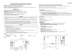
Thank you for purchasing the Mitsubishi Heavy Industries Superlink WEB Gateway
SC-WGWNA-A.
Before us, please be sure to read this User's Manual thoroughly for correct use. After reading this
manual, please store it in a secure place where it can be accessed easily. In the unlikely event
that something that you don't understand, or some serious trouble occurs during operation, be
sure to refer to this manual.
In addition, please read this manual in combination with the User's Manual provided with your air
conditioning system.
Table of Contents
■Safety Precautions ……………………………………………………………………………
■Introduction
……………………………………………………………………………………
System Outline …………………………………………………………………………………
Personal Computer Environment …………………………………………………………
Connections
……………………………………………………………………………………
Personal Computer Initial Configuration …………………………………………………
■Operation
………………………………………………………………………………………
Logging In
………………………………………………………………………………………
Over View Monitor screen
…………………………………………………………………
Common Operations in Each screen ……………………………………………………
Individual Monitor screen ……………………………………………………………………
Control Command screen ……………………………………………………………………
System Stop/Release screen ………………………………………………………………
Configuration Menu screen …………………………………………………………………
Air-Con Cell Configuration screen …………………………………………………………
Air-Con Configuration File Upload screen ………………………………………………
Air-Con Configuration File Download screen
…………………………………………
Communication/Buzzer Configuration screen …………………………………………
Link Configuration screen ……………………………………………………………………
Security Configuration screen ………………………………………………………………
Authentication Configuration screen ………………………………………………………
Calendar Configuration screen ……………………………………………………………
Schedule Master Configuration screen …………………………………………………
Schedule Control screen ……………………………………………………………………
Calender/Schedule Backup File screen …………………………………………………
Date Time Set screen …………………………………………………………………………
NTP Configuration screen ……………………………………………………………………
■Troubleshooting
………………………………………………………………………………
1
2
2
3
3
3
5
5
6
7
8
9
9
10
11
12
13
14
15
16
16
17
18
19
20
22
23
24
■Safety Precautions
■ Before use, please be sure to read these Safety Precautions in order to ensure proper operation.
■ The safety precautions included here are categorized as either “
Warning” or “
Caution,” those
items which could lead to death or serious injury, or other major consequences if this product is
used incorrectly have been listed under the “
“
Warning” category. Incorrect use under the
Caution” category could lead to serious consequences depending on the conditions, so these
items should also be treated as of major importance.
■ Symbols used in this manual have the following meanings.
Be sure to perform this
construction activity with all
equipment, etc. grounded.
Be sure to follow the
instructions given.
■ After you are finished reading this manual, be sure to keep it in a safe place where it can be
accessed easily. Also, if the persons using this product are different individuals, please give this
manual to them and have them read it thoroughly.
■Installation Precautions
Warning
Please ask the dealer where you purchased this product to install it.
If you try installing it yourself, and make a mistake, it could lead to electric shock, fire or other serious
consequences.
Please place this product n a location that can be locked for the sake of
security.
The WEB Gateway unit is equipped with an external power supply terminal block.
Please be sure to place it in a protected location to prevent electric shock and wrongful operation of the power
switch.
Caution
Be sure to ground this unit.
Do not attach the ground wire to a gas pipe, tap water line, lightning rod or telephone ground wire.
If grounding is imperfect, it could cause electric shock.
■Installation Usage
Warning
Please do not take the lid off this product.
This product has several precision circuit boards.
If you take the lid off, and make a mistake, this product could be broken.
1
■Introduction
Superlink WEB Gateway is a device which carries out centralized monitoring and control of packaged air-conditioners
from a personal computer.
■System Outline
The diagram below shows the system configuration. The WEB Gateway is connected to the personal computer
used for monitoring and control by Ethernet cable.
A logical unit of monitoring and control is the “Air-con Cell” which consists of indoor units and corresponds to a
remote controller group.
Internet
Explorer
Personal Computer for Control
and Monitoring
Ether net 10Base-T or 100Base-TX
connecting with a HUB or a cross cable
WEB Gateway
(SC-WGWNA-A)
SUPERLINK NO.1 network
SUPERLINK NO.2 network
*2
CE LL P+1
CELL 0
Indoor Unit
IU-0
*2
R
Indoor Unit
IU-1
Indoor Unit
IU-0
R
CE LL P+2
Indoor Unit
IU-1
R
CELL 1
Indoor Unit
IU-2
R
Indoor Unit
IU-2
*1:Max 64 indoor units can be connected in
New SUPERLINK system for one
CE LL Q
CELL P
Indoor Unit
IU-46
R
SUPERLINK network.
Indoor Unit
IU-46
R
Max 48 indoor units can be connected in
Previous SUPERLINK system for one
Indoor Unit
IU-47
Indoor Unit
IU-47
SUPERLINK network.
*1
*1
2: On new SUPERLINK system, the WEB
Gateway can be switched to work in one
SUPERLINK network and Max. 128
indoor units can be connected to the
Outdoor Unit
OU-0
SUPERLINK network.
Outdoor Unit
OU-0
Consult with the dealer to switch the
WEB Gateway.
Outdoor Unit
OU- 11
Outdoor Unit
OU-11
2
■Personal Computer Environment
CPU
500 MHz or higher
Memory
512 MB or above (1GB or above is recommended)
OS
Windows 2000 or Windows XP (Home/Professional)
Windows Vista SP1 or above on some conditions (See p. 14)
Monitor
Capable of 1024 x 768 or higher resolution display monitor.
(1280 x 1024 is recommended)
Browser
Internet Explorer version 6 or 7
■Connections
●If a private Ethernet connection is used (recommended)
This method is used to set up a private connection between WEB Gateway and the personal computer used for
monitoring and control.
Connection Method
Connect the WEB Gateway and personal computer directly using a 10BASE-T or 100BASE-TX Ethernet cable
(cross cable).
If a HUB is used, do not connect other devices to that HUB.
●If an Internet or intranet connection is used
If WEB Gateway is connected via the Internet or intranet (office LAN) environment, please consult with the
dealer. It is possible for them to arrange for connections on a charged work basis.
■Personal Computer Initial Configuration
●Configuration in the case of an private Ethernet connection
Communications settings (TCP/IP settings) in the monitoring and control personal computer are necessary. For
details, please read the operation manual supplied with your personal computer.
If this WEB Gateway is used as the factory set IP address, the setting for a PC address is as shown
below.
IP Address
192.168.0.1 - 192.168.0.254
(However, WEB Gateway uses 192.168.0.110, so use an IP address other than this.)
Subnet Mask
255.255.255.0
Default Gateway
Not specified
Preferred DNS Server
Not specified
Alternate DNS Server
Not specified
●Configuration in the case of Internet or intranet connections
Please consult with the dealer. It is possible for them to arrange for connections on a charged work basis.
3
●Browser (Internet Explorer) Configuration
Open Internet Explorer, then select “Internet Options” from the “Tools (T)” Menu at the top of the screen and
carry out the following settings.
・In “General”
Home Page
・In “Security”
Internet
Local Intranet
http://192.168.0.110/en
(If you changed the IP address of the WEB Gatewy, you have to input that IP
address, instead of 192.168.0.110, in the address column, the WEB Gateway
login screen will open when your browser is started.)
Default Level “Medium”
After clicking on the Internet tab, click on the “Default Level” button.
Default Level “Medium-low”
After clicking on the Local Intranet tab, click on the “Default Level” button.
・In “Privacy”
Default Level “Medium”
Click the “Default” button.
If the privacy setting is set on “Medium-high” or higher, WEB Gateway
cannot be used, so be sure to set the default value on “Medium.”
・In “Connections”
Set it so a proxy server is not used.
・In “Advanced”
Default Value
It is recommended that the browser be used with the default values. Click the
“Restore Defaults” button.
When you are finished with all the settings, click the “Apply” button, then click the “OK” button.
4
■Operation
■Logging In
The login screen is the starting screen for WEB Gateway. The login screen is displayed by inputting the
URL of the WEB Gateway from the personal computer’s WEB browser.
1. Start the personal computer’s browser (Internet Explorer).
2. Input the following URL, http://192.168.0.110/en in the address bar, then
press the Enter key.
If your WEB Gateway’s IP address has been changed, the above IP address “192.168.0.110” should be
replaced by the new IP address.
2
3
3. Input the User ID and Password, then click the Login button.
This screen is where you log in to WEB Gateway and where users who are performing control and
monitoring operations have their User ID and password verified. There are differences in authority
depending on the user who logs in, with the following three categories of authority.
System Administrator
Can operate all screens.
Control and Monitoring User
Cannot operate the Configuration menu.
Monitoring User
Is authorized to use the monitoring screen only and cannot
perform any control operations.
・User ID and Password of each user when shipped from the factory
User Category
User ID
Password
System Administrator
Admin
123456
Control and Monitoring User
Controller
123456
Monitoring User
User
123456
Note
The User ID and Password can be changed in the Authentication Configuration screen. (See p. 16.)
5
■Over View Monitor screen
This screen is for monitoring the overview of the whole packaged air-conditioner system on the one screen. It is
capable of monitoring up to 96 air-con cells (indoor unit remote controller group connection units). It displays the
name of each air-con cell, an error display icon, and On/Off/Operation Mode icon.
This screen is displayed when you log in.
Note
・ The Over View Monitor screen is refreshed automatically (automatic update) at regular intervals. Refreshing the
screen may take several seconds depending on the network’s status and the personal computer’s performance.
The refresh interval can be set at between 10 seconds and 60 seconds. (See p. 14.)
・ The characters and icons on the screen might move slightly at the time of redraw, but this is a characteristic of
Internet Explorer.
1
2
Over View Monitor screen
6
・ When the “Buzzer ON” is selected on the Communication/Buzzer Configuration screen, the alarm buzzer
function that raises the warning by sounding the buzzer when any error has occurred on an air-con cell, is enabled.
The alarm buzzer function operates not only on this screen but also when whichever of screens on this Gateway
is displayed.
When the buzzer is sounding, the Logo section shown at the right side of the screen title on all screens changes to
the Buzzer stop button. Clicking the Buzzer stop button stops the buzzer sound.
3
Overview monitor screen when the buzzer is sounding
■Common Operations in Each screen
1. Displaying a different WEB Gateway (when multiple WEB Gateways are connected)
Currently, the Over View Monitor screen of the WEB Gateway on the left end is displayed. To display the
screen of other Gateways, click the link characters for the name of the WEB Gateway on the right side.
2. Displaying a different function screen
To display each function screen, click the link characters (“Air-con Control”, “Schedule control”, etc.).
3. To stop the buzzer
・ Click the “Buzzer stop” button. This stops the buzzer sounding on the Over View Monitor PC connected
to this Gateway.
・ Since the volume of buzzer sound is set on the Over View Monitor PC, adjust the volume, if necessary,
on the PC.
・ When the buzzer sounds while this screen is minimized, maximize the screen first and then click the
Buzzer stop button.
・ When another application is executing on the front window and the Internet Explorer is put on the
background, bring this screen to the front and then click the Buzzer stop button.
Note
If the login screen is displayed when you click the link on the screen such as “Air-con Control”, that means the
power of the WEB Gateway turned off and started again. Please login again. (See p.5.)
7
■Individual Monitor screen
This screen is for indicating the detail information on one of the air-con cells by the pop-up window in front of the
Over View Monitor screen.
1. Click on the name of the air-con cell you would like to monitor.
The individual monitor screen will be displayed in a pop-up window.
Note
・ The Individual Monitor screen is refreshed automatically (automatic update) at regular intervals.
Redrawing the screen may take several seconds depending on the network’s status and the personal
computer’s performance.
The refresh interval can be set at between 10 seconds and 60 seconds. (See p. 14.)
・ The characters and icons on the screen might move slightly at the time of redraw, but this is a
characteristic of Internet Explorer.
After the pop-up window opens, clicking on different air-con cell name will cause the previously opened
pop-up window to close and a new pop-up window to open in the same place.
1
8
■Control Command screen (Admin or Controller can use this screen.)
This screen is for control command input operation to each air-con cell.
1. Click the “Air-con Control” link in the Over View Monitor screen.
The Control Command screen will be displayed. (Drawing the screen may take several seconds depending
on the state of the network, etc.)
2. Select control command values from the pull-down menus for each control item.
Select each control command value.
3. Click the Set button.
Note
In some models of indoor units, cannot be set to Powerful, and cannot be display to it.
2
3
■System Stop/Release screen (Admin or Controller can use this screen.)
This screen is for operation of stops or releases all the air-conditioners connected to WEB Gateway.
<System Stop>
1. Click the “System Stop” button.
All the indoor units under this Gateway immediately stop and set as the Remote controller Lock mode, then
the screen will return to the Over View Monitor screen.
Note Operation of air-cons from the Control Command screen is possible even during a system stop.
1
9
<System Release>
1. Click the “System Release” button during a System Stop.
The stopped state is system release in all air-cons, the system returns to the Over View Monitor screen and
the previously set operation schedule is enabled from that point on.
2. Operating Each Air-con
Even when the system stop condition becomes released, the air-cons will not start operating, so start
operation manually.
All Remote controller operation become unlock after released.
1
■Configuration Menu screen (Admin can use this screen.)
This screen can only be used by the user who has been verified by system administrator logging in. This screen is
displayed when “Configuration Menu” link is clicked on from each of the other screens.
The Configuration menu is shown below.
10
■Air-con Cell Configuration screen (Admin can use this screen.)
This screen is used to define each air-con cell which consists a number of indoor units and set names for each cell,
such as “Conference Room A.”
1. Click “Air-con Cell Configuration” in the Configuration Menu screen. (See p. 10.)
A list of indoor units which comprise each air-con cell will be displayed.
(Drawing the screen may take several seconds depending on the network state.)
2. Assign air-con cell numbers by giving each one a SL (Superlink) System No.
and SL (Superlink) Address.
Inputting the same air-con cell No. for multiple indoor units (SL Addresses) defines them as being in the
same group, that is an air-con cell. Corresponds an air-con cell to a remote controller group.
3. Input the air-con cell names and descriptions.
You can input the air-con cell name and description on the line of the indoor unit with the lowest SL
Address in the air-con cell.
Note
・ It is possible to input an air-con cell name with up to 16 characters and description with up to 64
characters.
・ The contents of the Air-con Cell Configuration cell settings can be saved in CSV files and uploaded.
(See p. 12.)
4. Click the Set button.
2
4
11
3
■Air-con Configuration File Upload screen (Admin can use this screen.)
This screen is used to upload Air-con Cell Configuration files from the personal computer to WEB Gateway.
An Air-con Cell Configuration file is a CSV file in which data recodes are indexed by air-con cell No., and the
SL system No., SL address, air-con cell name and description of each indoor unit comprises the air-con cell. If a
CSV file (PACinfo.csv) in a personal computer is uploaded to the WEB Gateway, the contents of this file will be
used for the Air-con Cell Configuration screen. A CSV file name is case sensitive, so care should be taken to
input them correctly as “PACinfo.csv”.
<Examples of PACinfo.csv files>
Air-con Cell No.
SL System No.
C00
S1
C01
S1
C01
S1
C02
S1
:
:
SL Address
U00
U01
U02
U04
:
Indoor Cell Name
Room 01
Room 03
Description
This room is Cell 00.
This room is Cell 01.
Room 04
:
This room is Cell 02.
:
<How to interpret the above table.>
・ The indoor unit with the SL address U00 in Superlink system SL1 is set in air-con cell No. C00.
・ Indoor units with SL address U01 and U02, respectively, in Superlink system SL1, are set in air-con cell C01,
and these two indoor units are grouped together as a single logical object. The indoor unit with the lower SL
address becomes the representative unit in the cell, and the indoor cell name and description are set.
・ The address U03 is omitted, but this indicates that indoor unit U03 is not currently connected. (Even if the
affected line is deleted, the setting shows that the indoor unit is not connected.)
・ Air-con cell No. designation does not have to be in serial order, but in the Over View Monitor screen the
air-con cells are displayed in the order of their cell No.
1. In the Configuration Menu, click “Air-Con Cell Configuration File Upload”.
(See p. 10.)
2
3
2. Click the Browse button and select “PACinfo.csv”.
3. Click the “Upload” button.
12
■Air-Con Configuration File Download screen (Admin can use this screen.)
This screen is used to download an Air-con Configuration file to the personal computer and save them as
CSV files.
1. In the Configuration Menu, click “Air-con Cell Configuration File Download”. (See p. 10.)
2
2. Click “Download” button, then select “Save”.
3. Specify the save destination, then save the file.
The “PACinfo.csv” file will be saved.
Note
If Excel is installed in your personal computer, double clicking on the PACinfo.csv file causes Excel to open
and enables direct editing of the file.
Note
In case that the WEB Gateway is used in one SUPERLNK network and maximum 128 indoor units are
connected to the SUPERLINK network, the “PACinfo_128.csv” file will be saved. In the file, SL Address is
described in three digits as “U000 - U127”.
13
■Communication/Buzzer Configuration screen (Admin can use this screen.)
This screen is used to set the WEB browser’s monitoring screen refresh interval.
1. In the Configuration Menu, click “Communication/Buzzer Configuration”. (See p. 10.)
2. Set the screen refresh interval.
Set the screen refresh interval at between 10 and 60 seconds. (It is set at 30 seconds at the factory.)
Note
The maximum delay time from the time the air-con’s status changes until the change is reflected in the
personal computer screen is virtually decided by this setting. If the time set for this interval is short, there
may be some flickering on the screen from the WEB browser, so it is recommended that the refresh time be
set at about 30 seconds.
3. When using the alarm buzzer function, put a tick (√) in the "Buzzer ON" check
box.
4. In the case of the IP address change.
4-1. Input the desired IP address and the subnet mask.
Caution
If a wrong IP address is input, the WEB Gateway will not be accessed anymore.
Ex: Correct: 192.10.1.1
Incorrect: 192.010.001.001
4-2. If necessary, input the default Gateway IP address.
Note
Consult with the network administrator if a default Gateway setting is necessary.
5. In the case of Windows Vista is used.
5-1. Put a tick (√) in the “Display Restart Message” check box.
5-2. Set the display restart message day(s).
Set the display restart message day(s) at between 1 and 90 days. (It is set at 30 days at the factory.)
6. Click the “Set” button.
2
3
4-1
4-2
5-1
5-2
6
14
■Link Configuration screen (Admin can use this screen.)
This screen is used to set the WEB linkages among a number of WEB Gateways.
1. In the Configuration Menu, click “Link Configuration”. (See p. 10.)
2. Input Link Names and IP addresses of the destination WEB Gateways.
Note
The position of an input column determines the position of the Linked Name Tab on top of other screens. By
clicking a Link Name Tab, the current screen will be switched to the corresponding screen on the other
linked WEB Gateway.
This WEB Gateway recognizes the input name as its own Link Name when the input IP address matches its
own IP address. Then its own Link Name Tab is displayed with dark gray.
3. Click the “Set” button.
2
3
15
■Security Configuration screen (Admin can use this screen.)
This screen is which the IP address filtering can be set.
Note
Be careful not to make any mistakes in setting the IP address.
No addresses are set at the factory, so any personal computer with any IP address can access WEB
Gateway.
However, if even one IP address is entered in this screen for which access is permitted,
WEB Gateway can be accessed from only the personal computer with that address.
1. In the Configuration Menu screen, click “Security Configuration”. (See p. 10.)
2. Input the IP address of the personal computer for which access is permitted.
3. Click the Set button.
2
3
■Authentication Configuration screen (Admin can use this screen.)
This screen is used to set and change the User Name, Password, and Authentication to each screen when logging
in to this Gateway.
1. In the Configuration menu screen, click “Authentication Configuration”. (See p. 10.)
2. Input the User Name and Password.
Input a User Name that is within 10 bytes and a Password that is within 8 bytes in length.
3. Select the access rights.
4. Click the “Set” button.
2
3
4
16
■Calendar Configuration screen (Admin can use this screen.)
This screen is used to set the special dates for the coming 12 months.
Note If change Schedule Master Configuration during this week, can’t change Schedule.
Need to change schedule in Schedule Control screen. (See p. 19.)
1. In the Configuration Menu screen, click “Calendar Configuration”. (See p. 10.)
The calendar for the current month will be displayed.
2
4
3
2. Select the month that you would like to set.
The calendar for the month you selected will be displayed.
(It may take several seconds to draw the calendar screen depending on the network conditions, etc.)
3. Select an item from the pull-down menu.
Normal Days
Date for setting the schedule master for each day of the week
Holiday, Special Day 1, Date for setting a special schedule master regardless of which day of the week
Special Day 2
it is
When setting individual days one by one, select from the pull-down menu whether the day is an ordinary
day, holiday, special day 1 or special day 2.
4. Click the “Set” button.
Note
・ If you jump to the screen for another month without clicking the “Set” button, or if you click the
“Undo” button, all the contents input in this screen will be destroyed, so exercise caution.
・ There is one calendar for one WEB Gateway. All the air-con cells in a WEB Gateway are run from
the same calendar.
・ The calendar in this screen is displayed in the form of year-month-day, but the calendar year is not
displayed. For this reason, the calendar settings will not be erased when that day passes, but will be
used again the following year as that year’s settings.
・ Even if the Gateway’s power is turned off, the calendar settings are saved to memory.
17
■Schedule Master Configuration screen (Admin can use this screen.)
The schedule master is the data decided by the kinds of days defined in the Calendar (Monday, Tuesday,
Wednesday, Thursday, Friday, Saturday, Sunday, Holiday, Special Day 1, Special Day 2, 10 types). Actual
schedule actions are executed by the Schedule Control on the next page. Everyday, at the change of date, the
data of the Schedule Control are shifted by one day, and one day data is copied from the Schedule Master to the
7th day data of the Schedule Control.
Note The data of the Schedule Master will copied and activated form 7 days after.
If the data of the Schedule Master is required to be activated immediately, set the date of this WEB
Gateway as 7 days advanced temporally by the Date Time Set screen (see p.24.), then, reset the date as
the right date. The entire data of the Schedule Control is set as the Schedule Master immediately, and
executed.
Note If change Schedule Master Configuration during this week, can’t change Schedule.
Need to change schedule in Schedule Control screen. (See p. 19.)
1.
In the Configuration menu screen, click “Schedule master Configuration”. (See p. 10.)
In the initial screen, the air-con cell of lowest cell No. is displayed.
2
4
3
2. Select the air-con cell name and the schedule date.
The display will change to the corresponding Schedule master Configuration screen.
3. Select and input the desired settings for each schedule item.
In this screen, the following items can be set as schedule items.
Time
00:00 ~ 23:59 (1 minute intervals.)
On/Off
Blank (not specified), On, Off
Mode
Blank (not specified), Auto, Heating, Cooling, Fan, Defrost
Fan Speed
Blank (not specified), Powerful, High, Medium, Low
Set Point
Blank (not specified), 18.0ºC ~ 30.0ºC, 0.5ºC increments
Remocon Lock/Unlock
Blank (not specified), Lock, Unlock
5 items (On/Off, Mode, Fan Sped, Set Point, Remocon Lock/Unlock) can be set together for 1 time setting.
Up to 20 settings can be set.
4. Click the “Set” button.
Note
・ If you jump to the screen for another month without clicking the “Set” button, or if you click the
“Undo” button, all the contents input in this screen will be destroyed, so exercise caution.
・ This schedule master is referred once a day and a new execution schedule edited from it.
・ Even if the schedule master is changed, it has no influence on the current execution schedule.
・ The schedule master can be copied to another master.
・ Select the air-con cell name and desired schedule date of the destination , then click “Copy.”
・ In some models of indoor units, cannot be set to Powerful, and cannot be display to it.
18
■Schedule Control screen (Admin or Controller can use this screen.)
This screen displays the execution schedule composed from the schedule master and calendar for each air-con
cell, and is used to input data and edit the execution schedule. Everyday, at the change of date, the data of the
Schedule Control are shifted by one day, and one day data is copied from the Schedule Master to the 7th day data
of the Schedule Control.
Note If want to change Schedule during this week, change schedule in this Schedule Control screen.
1. From the Over View Monitor screen, click “Schedule Control.”
In the initial screen, the execution schedule of the cell with the lowest cell No. is displayed.
(It may take several seconds to draw this screen depending on network conditions.)
2
4
3
2. Select the air-con cell name and corresponding schedule date.
Select the air-con cell name and corresponding schedule for the cell that is being displayed and edited. A
seven-day execution schedule from the current day to 6 day in advance can be displayed and edited.
3. Select and Input Each Schedule Item
The following items can be set as schedule items in this screen.
Time
00:00 ~ 23:59 (1 minute intervals.)
On/Off
Blank (not specified), On, Off
Mode
Blank (not specified), Auto, Heat, Cool, Fan, Dry
Fan Speed
Blank (not specified), Powerful, High, Medium, Low
Set Point
Blank (not specified), 18.0ºC ~ 30.0ºC, in 0.5ºC increments
Remote Lock/Unlock
Blank (not specified), Lock, Unlock
Up to 20 settings can be set.
4. Click the “Set” button
Note
・ If you jump to the screen for another month without clicking the Set button, or if you click the “Undo”
button, all the contents input in this screen will be destroyed, so exercise caution.
・ Clicking the “Load Master” button causes the schedule to be loaded from the annual calendar and
schedule master and displayed on the screen. It the “Set” button is then clicked, the execution schedule
is set from the master.
・ The instructions and display contents in this screen can be copied to another air-con cell or another date.
Select the air-con name and corresponding schedule date that is the destination, then click “Copy.”
・ This Gateway updates the execution schedule once a day at 00:00 in the middle of the night.
・ The actual operation schedule is in accordance with the execution schedule displayed in this screen, but
when the system is operated using the remote controller, etc. it may not run in accordance with the
schedule.
・ When all the indoor units are shut down by a forced stop, not only does operation stop, but the entire
execution schedule will not be executed.
・ In some models of indoor units, cannot be set to Powerful, and cannot be display to it.
19
■Calendar/Schedule Backup File screen (Admin can use this screen.)
This screen is used to download or upload the backup files for configurations of the calendar, schedule and
execution schedule (called hereafter the schedule backup files).
<When downloading>
1. From the Configuration Menu screen, click "Calendar/Schedule Backup File
Download". (See p. 10.)
2
2. Click the Download button.
3. Specify the saving address and save.
File “schedule.tgz” is saved.
20
<When uploading>
1. From the Configuration Menu screen, click "Calendar/Schedule Backup File
Upload". (See p. 10.)
2
3
2. After clicking the Reference button, select the file to upload.
Note
Since the schedule backup file is a binary file special to this Gateway, the downloaded file cannot be edited
or uploaded.
3. Click Upload button.
Note
After the upload of schedule backup file, this Gateway reboots automatically. Access once again approx. 5
minutes later.
21
■Date Time Set screen (Admin can use this screen.)
This screen is used to set the internal time clock on the CPU board in the WEB Gateway.
The schedule control is executed in accordance with this clock setting, so in order to assure correct operation, it
is necessary to correct the setting on this clock.
1. In the Configuration Menu screen, click “Date Time Set”. (See p. 10.)
In the initial screen, the Gateway’s current time is set in the time input column.
2
3
2. Input the time.
The time can be input within the following ranges.
AD Year
2000 ~ 2037
Month
1 ~ 12
Day
1 ~ 31
Hour
0 ~ 23 (24-hour notation)
Minute
0 ~ 59
3. Click the “Set” button.
Note
・ The time is refreshed automatically once every 2 seconds, but thee is an error of several seconds. The
time needed for a refresh screen depends on various conditions, and therefore may take several seconds.
・ Leap year processing is also executed automatically.
22
■NTP Configuration screen
(Admin can use this screen.)
This screen is used to set the automatic synchronization to an NTP server for the WEB Gateway's clock.
Caution
Before setting this NTP configuration, be sure to set correct clock time. (See p. 22.)
1. In the Configuration screen, click "NTP Configuration". (See p. 10.)
2
3
4
5
2. When using the NTP function, put a tick(√) in the "Use NTP Service" check box.
3. Input the IP address of the NTP server.
Note
Consult with the network administrator about the IP address of the NTP server.
4. Select difference in time with UTC of area to use.
Caution
If the "Difference in time with UTC" is not set, the WEB Gateway's clock will be set as
wrong clock.
Note
When the NTP service is not used, the "Difference in time with UTC" setting is not necessary.
5. Click the “Set” button.
Note
The WEB Gateway will be rebooted automatically when the "Set" button is pressed. After that, the WEB
Gateway can not be accessed for about 5 minutes. Please login again.
23
■Troubleshooting
IP address was forgotten.
Incorrect IP address was
configured.
Consult with the dealer where you purchased this product.
Password was forgotten.
Security setting IP address was
forgotten.
The screen flickers.
During redraw the screen, this occurs for an instant until the new screen
is displayed. This is an inherent characteristic of Internet Explorer and
there is no problem.
If the flickering becomes pronounced, set the refresh rate at 60seconds.
Pop-up window cannot be seen.
After a pop-up window opens up to display an individual monitoring
screen, if you click on the Over View Monitor screen window in the
background, the individual monitoring window will be hidden.
Select the pop-up window again by clicking on the button in the task bar
at the bottom of the screen, or select the desired individual monitoring
window from the overall monitoring screen again.
The screen shows connection
errors.
Push “Update” switch in Internet Explorer. Next, restarts Internet
Explorer.
Restart Internet Explorer regularly.
The PC freezes in a couple of
months each.
Please confirm whether the “Display Restart Message” check box is
ticked on Communication/Buzzer Configuration screen. (see p.14)
If the OS of the PC is Windows Vista, please confirm the version.
In case it is initial version, update it to SP1 or above.
24
MEMO