1
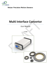
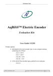
DS-130-datasheet-V2.2 , AUG 2015
DS-130 Absolute position, rotary Electric Encoder™
The DS-130 is a member of the DS series of Electric Encoders™,
based on Netzer Precision proprietary technology. The Electric
Encoder™ offers many advantages - some unparalleled
Low profile (10mm).
Hollow, floating shaft.
No bearings or other contacting elements.
High resolution and precision.
High tolerance to temperature extremes , shock, moisture, EMI,
RFI and Magnetic fields.
Very low weight.
Holistic signal generation
Absolute Position over digital interfaces.
Mechanical
Allowable mounting eccentricity
Allowable rotor axial motion
Rotor inertia
Total weight
Outer Ø /Inner Ø/ Height
Material (stator, rotor)
±0.1 mm
±0.1 mm
12.378 gr · mm2
65 gr
130 / 90 / 10 mm
Ultem™ polymer
Electrical
Supply voltage
Interconnection
Cable Length
Environmental
EMC
Operating temperature range
Relative humidity
Shock endurance
Vibration endurance
Protection
The absence of components such as ball bearings , flexible
couplers, glass disc, light sources and detectors, along with very
low power consumption makes the Electric Encoder™ virtually
failure free.
The internally shielded, DC operated Electric Encoder™ includes
an electric field generator, a field receiver, a sinusoidal shaped
dielectric rotor, and processing electronics.
The output signals of Electric Encoder™ are analog Sine / Cosine
representing the rotation angle. The digital outputs are obtained
by further processing - which may be either internal or external
to the encoder.
The combination of precision, low profile, low weight and high
reliability have made Netzer Precision encoders particularly
suitable to a wide variety of critical applications including, but
not limited to medical equipment and aerospace.
5V ± 5%
Shielded cable or
1,500 mm MAX
IEC 6100-6-2, IEC 6100-6-4
Digital: -40°C to +85°C
98% Non condensing
100 g for 11 ms
20 g 10 – 2000 Hz
IP 40
Characteristics
Angular resolution
Static error
Maximum operational speed
Measurement range
Power On - Max. operational speed
Build In Test BIT
www.netzerprecision.com
The Electric Encoder™ is unique in being holistic, i.e., its output
reading is the averaged outcome of the whole area of the rotor ,
This feature makes the Electric Encoder™ forgiving to mounting
tolerances, ball bearing wander etc.
19 bits ; 524,288 CPR
< 10 mDeg
750 rpm
Unlimited rotation
3.3 RPM , <=20°/sec
Optional
1
DS-130-datasheet-V2.2 , AUG 2015
DS-130 Absolute position, rotary Electric Encoder™
Digital SSi Interface
Synchronous Serial Interface (SSI) is a point to point serial
interface standard between a master (e.g. controller) and a slave
(e.g. sensor) for digital data transmission.
SSI data transmission timing diagram
n * T
t1
T
t3
Clock
a
1
2
3
n
n ‐ 1
Data
Monoflop
1/T
t1
t2
t3
SSi
Monoflop time
1
0
LSB
MSB
Digital BiSS-C Interface
BiSS – C Interface is unidirectional serial synchronous protocol
for digital data transmission where the Encoder acts as “slave”
transmits data according to “Master” clock. The BiSS protocol is
designed in B mode and C mode (continuous mode) .The BiSS-C
interface as the SSi is based on RS-422 standards.
BiSS-C data transmission timing diagram
25 μSec
n+1
Description
Recommendations
Total number of data bits
Clock period (sec)
User defined
Clock frequency 0.5 ÷ 2.0 MHz
2.0 MHz
(user defined)
Minimum time required for the
encoder to freeze data and preset
T/2
the shift registers before receiving
the first rising edge to prompt the
MSB
Data transmission delay
“0” on standard
(increases with cable length)
cable length
Required delay to refresh position
data between subsequent posi>25 μSec
tion
Clock
SSi / BiSS interface wires color code
Clock +
Grey
Clock
Clock Blue
Data Yellow
Data
Data +
Green
GND
Black
Ground
+5V
Red
Power supply
Data
CLK / NCP RX [+]
(gray)
CLK / NCP RX [‐]
(blue)
DATA / NCP TX [‐]
(yellow)
DATA / NCP TX [+] (green)
Gnd
(black)
5V
(red)
www.netzerprecision.com
Ack Start “0” Position CRC Timeout
bits (6 bits)
bit #
Description
Software tools: (SSi / BiSS - C)
Advanced calibration and monitoring options are available by
using the factory supplied Electric Encoder Explorer software,
This facilitates proper mechanical mounting , offsets calibration
and advanced signal monitoring.
27
Ack
26
Start
25
“0”
Period during which the
encoder calculates the
absolute position , one
clock cycle
Encoder signal for “start”
data transmit
“start” bit follower
6...24
AP
Absolute Position encoder
data
Host System
Electric Encoder™
n
T
t2
SSi / BiSS Output signal parameters
Signal latency
~250 μSec
Output code
Binary
Serial output
Differential RS-422
Clock
Differential RS-422
Clock Frequency
0.5 ÷ 2.0 MHz
Position update rate (Max)
30 KHz
Current consumption
180 mA
5V
0...5
5V
120 Ω
2
The CRC polynomial for
position, error and warning data is: x6 + x1 + x0. It is
MSB first and
CRC transmitted
inverted.
The start bit and “0” bit
are omitted from the
CRC calculation.
between the
Time- Elapse
“start”request
out sequential
cycle’s.
Default
Length
0
1/clock
1
1 bit
0
1 bit
25 μs
DS-130-datasheet-V2.2 , AUG 2015
DS-130 Absolute position, rotary Electric Encoder™
DS - 130 -
64
- 3S H - S
0 - n n n
DS Product line
nnn - Custom
Outer Diameter
Fine ECR
C - Connector (optional)
Outputs:
Interconnection:
S - Digital : SSi
I - Digital : BiSS-C
S - shielded cable (default)
R - Strain relief & shielded cable
Resolution
Code Bit
CPR
H
19 524,288
Netzer Cat No.: CB‐00014
Provider: Ray‐Q USA. wire CAT No: RQ213210
Cable: 30 AWG twisted pair (3) :2 (30 AWG 25/44 finned copper , 0.15 PFE to Ø0.6 ± 0.05 OD).
Temperature rating: ‐60 to +150 Deg C. Braided shield: Thinned copper braided 95% min. coverage. Jacket: 0.45 silicon rubber jacket Ø3.45 ±0.2 OD
Pair #
Color
1
2
3
Red / Black
Gray / Blue
Green / Yellow
30 AWG twisted pairs (3)
Braided shield
Related documents:
DS-130 User Manual : Mechanical , Electrical and calibration setup.
Demonstration Kit:
DS-130DKIT-01: Includes ,mounted encoder on rotary jig ,
and RS-422 to USB converter.
30 AWG single
insulated wire
0.017
Jacket 0.45mm
3.45 ± 0.20mm
Ø 0.61 ± 0.051mm
www.netzerprecision.com
3
DS-130-datasheet-V2.2 , AUG 2015
DS-130 Absolute position, rotary Electric Encoder™
1
2
3
4
6
5
7
8
REVISIONS
A
REV.
DESCRIPTION
DATE
APPROVED
A
2.30 TYP6
130
2.40
0.1 A
6
6 PLACES
4.40
TYP6
B
MOUNTING SURFACE
4.30
A
2.90
ZONE
B
R4
12 PLACES
C
93
0
127 -0.05
5
.0
+0 0
90
C
141
REF
D
135
D
A
A
1.50
9.70
MOUNTING SURFACE
SECTION A-A
E
The information contained in this drawing is the sole property of Netzer Precision Motion Sensors Ltd. Any reproduction in part or whole without the
written permission of Netzer Precision Motion Sensors Ltd.is prohibited. The drawing is confidential, and is the property of Netzer Precision Ltd. it must
not be disclosed to a third party without written consent of Netzer Precision Ltd.
DRAWN
CHK'D
F
1
www.netzerprecision.com
2
3
NAME
V.D
SIGNATURE
APPV'D
UNLESS OTHERWISE SPECIFIED:
DIMENSIONS ARE IN mm
SURFACE FINISH: N6
LINEAR TOLERANCES: 0.1 mm
ANGULAR TOLERANCES: 0.5 deg
ALL CHAMFER: 0.1 mm X 45°
4
4
DATE
19.08.15
TITLE:
DS-130 ICD
MATERIAL:
Coating:
DWG NO. :
Revision :
CAT NO. :
ICD-DS-130-00
SCALE: 1:1
00
A3
SHEET 1 OF 1
DS-130-datasheet-V2.2 , AUG 2015
DS-130 Absolute position, rotary Electric Encoder™
1
2
4
3
6
5
+0.05
127 0
A
3 THREADS M2 DEEP 5mm
EQ.SP
0.1 A
7
D
A
A
0
90 -0.05
0.05 A
0.02 B
0.05 A
8
0.05 A
B
B
B
3
80 max
93
120min
2
SECTION B-B
SECTION A-A
1
C
D
141
135
DETAIL D
2.50 min
0
1.60 -0.05
C
D
E
A
A
Shaft - End installation
No
1
8 THREADS M2 DEEP 5mm
EQ.SP
0.1 A
F
1
www.netzerprecision.com
2
3
4
Part
DS-130-64-3SH Included
Description
DS-130 encoder
3
MP-00329
2
3
MA-DS130-004 Optional
Socket head cup screw,Alen M2X4mm ,
St.St. ,DIN912
MP-00016-02
MP-00329
Included
Shaft End
installation kit
Critical dimensions marked with “*”
5
QTY.
1
6
1
6