1
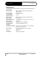
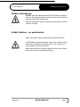
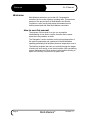
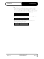
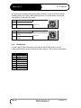
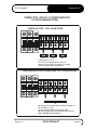
XL-2-Series
user manual
revision 1.1
www.moldmasters.com
Amendment Record
XL-2 Manual
Amendment Record
Issue
Date
1.0
July 04
1.1
Nov 05
XL-2 Series Manual
Amendments
Author
Authorised
First Issue
DT
JN
Re-organized format
DT
JN
Copyright © 2004 Mold-Masters® Developments
This manual is intended for use with the XL-2 Series Controller
Our policy is one of continuous improvement and we reserve the right to alter product
specifications at any time without giving notice.
Page 2
Mold-Masters®
Revision 1.1
XL-2 Manual
Contents
Contents
Amendment Record .........................................................................................2
Contents ..........................................................................................................3
Specifications...................................................................................................4
Safety Instructions ...........................................................................................5
Welcome..........................................................................................................6
Installation........................................................................................................7
Switching "On" and "Off" ..................................................................................8
Navigation........................................................................................................9
XL-2 Operation Diagram ................................................................................12
The Controller Cabinet...................................................................................13
How the XL-2 Controller Works......................................................................14
Setting up your controller ...............................................................................15
Running your controller..................................................................................19
Customizing your controller ...........................................................................23
Troubleshooting .............................................................................................27
Appendix A ....................................................................................................30
Index ..............................................................................................................35
Revision 1.1
Mold-Masters®
Page 3
Specifications
XL-2 Manual
Specifications
The following are general specifications. The actual controller supplied may differ in
specified options.
Supply Voltage
380v 3 phase 50Hz with neutral, others available
220/60Hz Delta
Control Method
PIDD self optimising
Operating Range
0…450°C
Control Accuracy
+/-1°C
Earth Leakage
Measurement
Earth leakage measurement on individual cards
(set at 100KΩ)
Thermocouple input
Iron Constantan Fe/Con type 'J', type ‘K’, or type 'L'.
Power output
16A/3600W
Temperature scale
Centigrade (Celsius) or Fahrenheit
Output Overload
protection
16A super-quick acting (FF) fuse
Card Diagnostics LED's
Zone1, Zone2, Ground Fault, T/C Fault, Temperature
Alarm, and Current Overload
Alarm Output
Double-pole change-over volt-free contacts,
1A max burden
Interface
Optional
Case Details
Heavy duty metal cabinet
Page 4
Mold-Masters®
Revision 1.1
XL-2 Manual
Safety Instructions
Safety Instructions
DO NOT enter the cabinet without first ISOLATING the supplies –
there are unguarded terminals inside the cabinet which may have
a dangerous potential across them.
WARNING
Where a three-phase supply is used then this potential may be at
380 volts or higher.
Safety Notices - an explanation
Within this manual, safety instructions are marked as follows:
A WARNING symbol and message, shown here, identifies where
there may be a hazardous situation which, if not avoided, may
result in death or injury to personnel.
WARNING
Revision 1.1
Most warnings pertain to electrical aspects and you must comply
with them to minimise any personal danger.
Mold-Masters®
Page 5
Welcome
XL-2 Manual
Welcome
Mold-Masters® welcomes you to their XL-2 temperature
controllers for hot runner injection moulding tools. This particular
member of the proven family of Mold-Masters Hot Runner
Controllers is user friendly and retains the standard control
facilities associated with other Mold-Masters controllers.
How to use this manual
The purpose of this manual is to give you a complete
understanding of how best to use the controller and to assist
where there are problems or faults.
The “Navigation” section contains a brief technical description of
the system components and a portrayal of the Mold-Masters
operating philosophy that facilitates precision temperature control.
The following chapters then take you carefully through the stages
of setting up, and running, a new control system. After considering
system maintenance the final sections look at trouble shooting to
assist in the unlikely occurrence of a system fault.
Page 6
Mold-Masters®
Revision 1.1
XL-2 Manual
Installation
Installation
Where to use this equipment
Mold-Masters Hot Runner temperature controllers are designed
for use in the plastic injection moulding industry as temperature
controllers for hot runner systems as commonly used in mould
tools. The controllers must not be used in residential, commercial
or light-industrial environments. Furthermore, they must not be
used in an explosive atmosphere or where there is a possibility of
such an atmosphere developing.
WARNING
They should be installed in a clean dry environment where the
ambient conditions do not exceed the following limits:
* Ambient temperature
0 to +50°C.
* Relative Humidity
90% (non-condensing)
When in use this equipment does not emit audible noise in excess
of 10dBA.
Controller — Tool Connections
The various connections to the system using the cables supplied
with the equipment are specified in Appendix A.
Controller Power Supplies
The control cabinet can be manufactured to accept a wide range
of supplies and sequence of phases. Refer to the serial plate in
the controller cabinet for confirmation of the supply requirements.
If the local supply is outside the specified range please contact our
Service department for advice.
Tel.: (1) 905-877-0185
(1) 800-450-2270
Fax: (1) 905-873-2818
Revision 1.1
Mold-Masters®
Page 7
Switching "On" and "Off"
XL-2 Manual
Switching "On" and "Off"
The main Power Switch is a rotary Switch at the back of the
cabinet. This Switch is sufficiently rated to disconnect the total
load current during switch “On” and switch “Off”. You can use a
suitably- sized padlock, or similar device, to lock the switch in the
“Off” position to prevent operation during maintenance.
Although the main switch has the capacity to switch the whole
system “Off”, we recommend that you only do this in an
emergency situation. A sequenced method for switching “On” and
“Off” protects the controller and keeps the switched load to a
minimum to extend the life of the main Isolator.
Switching On
Once the controller card is on, it gets into “Run” mode
automatically to start heating the tool.
Switching Off (or Shutting Down)
We recommend that you use the controller to shut down the
heating load, and only use the main isolator to switch off the whole
system once it is idle.
1. Shut down the heating
Use I/O switch to turn off each controller card.
2. Shut down the Controller
Now use the Main Rotary Switch on the cabinet to isolate all the
power from the whole system.
Page 8
Mold-Masters®
Revision 1.1
XL-2 Manual
Navigation
Navigation
This part of the manual introduces you to the controller card to
show what facilities are available and what information is
available.
Main Screens
Once the controller card is turned on, it always shows
Temperature Display Screen of the first zone in controller card.
There are three main screens in total, they always display actual
temperature on top display, and bottom displays are set
temperature, current reading, and power output percentage in that
specific zone. A decimal point beside the top right digit indicates
the amount of output power.
Temperature Display ➞ Current Display ➞ Power Output Display
•
Use
to rotate through different screens
Zones Switching
There are two zones per controller card. The two blue LEDs on
the right indicate which zone’s information is currently shown.
Zones can be switched anytime in Temperature Display, Current
Display, or Power Output Display to show reading accordingly.
•
Use
to switch between two zones to view display.
Function Menu
In this menu, you can put the controller into particular working
mode. However, Program Menu is used for changing controller
set-up. Manual and boost mode can be set independently in each
zone; however, standby mode always activate in both zones when
the mould-tool is paused.
Manual Mode (Hnd) ➞ Standby Mode (tdn) ➞ Boost Mode (tUP)
➞ Program Mode (Prog)
Revision 1.1
•
From any of the main screens, press and hold
seconds to get into Function Menu.
•
Use
•
to enter into your desire mode, or press
to get
Press
back to Temperature Display Screen without changing to other
mode.
or
for at least 2
to scroll through the menu.
Mold-Masters®
Page 9
Navigation
XL-2 Manual
Program Menu
Within this menu there are a number of controls that are provided
for you to customize your controller. You can select this menu
from the Function Menu only. Each zone has its own program
menu items to meet its own needs; however, there are some
items shared by two zones. Refer to “Customize your controller”
section for detailed explanation on each parameter in the menu.
Page 10
•
In Function Menu, use
to scroll to “Prog”, and then press
to enter into Program Menu.
•
or
to. Top display
Scroll through the menu by using
shows menu item, bottom shows setting. You cannot change
setting when bottom display is flashing.
•
to gain access for any changes by, bottom display
Press
then stays.
•
Use
or
to change setting, press
to save the change.
Bottom display starts flashing again. If bottom display stays,
pressing
to escape from Program Menu without changing
setting.
•
After changes are made, press
Display Screen.
Mold-Masters®
to return to Temperature
Revision 1.1
XL-2 Manual
Navigation
Front Panel Status Indication
There are two blue and four red LED indicators to show the status
of the controller card:
Zone1 display
Zone2 display
GND – earth leakage alarm indicator
Thermocouple failure – T/C break (LED stays) or
T/C polarity (LED blinks)
Temperature alarm – Over/under temperature alarm
indicator
Overload – Excess current cut-out alarm indicator
Keys Description
Increment up
- Change set temperature, power output % in manual
mode, or program parameter values
- Rotate through function and program menu
Decrement down
- Change set temperature, power output % in manual
mode, or program parameter values
- Rotate through function and program menu
Enter
- Rotate through Temperature, Current, and Power display
- Gain access and confirm program menu changes
- Press and hold it for 2 seconds to get out from special
working mode
Selector
- Toggle between two zones
- Press and hold it for 2 seconds to get into function menu
- Escape from function or program menu
I/O
- Turn controller card ON/OFF
Revision 1.1
Mold-Masters®
Page 11
XL-2 Operation Diagram
XL-2 Manual
XL-2 Operation Diagram
Main Screens
200.
200.
Press
03.5A
200C
025P
Power Output Display
Current Display
Temperature Display
Top: actual temperature
Bottom: set temperature in ºC
(It shows F if temperature is
in Fahrenheit)
200.
Press
Top: actual temperature
Bottom: power output %
Top: actual temperature
Bottom: current reading
*Decimal point besides top right digit indicates the power output percentage
Zone Switching
200.
225.
Press
200C
Zone 1 Display
Top LED lit up
Press and hold
for
at least 2 seconds
225C
Zone 2 Display
Bottom LED lit up
Function Menu
Press
Hnd
Manual Mode
Press
tdn
Standby Mode
tUP
Press
Prog
Program Mode
Boost Mode
Press
Program Menu
Ot
010
Over Temp. Limit
Page 12
Press
Ut
J L
010
J
Under Temp.
Limit
Thermocouple
Type
Mold-Masters®
Press
dSP
000
Alternating
Zone Display
Revision 1.1
XL-2 Manual
The Controller Cabinet
The Controller Cabinet
The power supply to the control cabinet is via a strain-relief
mounted cable gland plug wired in star or delta configuration.
(Please check your specifications for details of which configuration
has been configured.) Connections to the tool are by looms
terminating type Contact 24pole connectors with 48pole housing
or their equivalents. There are normally two types of cables
supplied; a thermocouple connection, using type H-BE24BS and
typical connector and wiring details are shown in Appendix A.
An alarm output option is available for extending the alarm, or,
perhaps, inhibiting the injection process.
Controller Cards
The controller card is dual-zone modular that provides real time
temperature control.
Each card has three main components:
• thermocouple amplifiers,
• CPU,
• multi-voltage output triacs.
Thermocouple Amplifiers
The thermocouple amplifiers have preset responses for both J and
L type thermocouples. The selection of sensor type can be done
in Program Menu; this in turn sets the differential amplifier to
match the selected thermocouple type.
Central Processor Unit (CPU)
The CPU provides the following facilities:
• closed and open loop control of the zones,
• processes thermocouple and current readings to show on
display,
• checks for alarm conditions, including excess current, incorrect
thermocouple wiring, zone over temperature condition, low
impedance between heater and ground, and generates alarm
information for the display screen and alarm relay,
• controls the output power to the on-board triac using a number
of self-tuning algorithms
• controls a row of diagnostic status indication
The card requires no analogue calibration and is ready for use
once set up from the display console.
Output Triacs
The controller card has an on-board triac that is capable of controlling
heating loads of up to 16 Amps peak.
Revision 1.1
Mold-Masters®
Page 13
How the XL-2 Controller Works
XL-2 Manual
How the XL-2 Controller Works
Mold-Masters® controllers are designed to perform in closed and
open loop configurations. However, we consider that the normal
operating mode is closed loop. This is illustrated in the following
diagram and explained below.
Temperature
Set Point
4
3
rt
rE = 120°C
2
1
Time
1. The zone controller slowly ramps up the heater power and
simultaneously looks for a positive temperature change at the
thermocouple input. The controller verifies the actual rate of rise
against a predetermined value in program parameter r1. Power is
slowly increased until the correct rate of rise is achieved.
2. At ramp temperature rE, the dwell time rt is activated (2minutes),
this permits any residual moisture in the heating elements to be
eliminated. After all zones reached to ramp temperature, they will
start heating up together again.
3. The controller continues to ramp up the temperature to the set
point with the speed set in program parameter r2, which should be
achieved with minimum over-shoot.
4. Having built a virtual model to map the tool and heater
characteristics, the controller can maintain the temperature at an
accurate point with virtually no deviation.
Page 14
Mold-Masters®
Revision 1.1
XL-2 Manual
Setting up your controller
Setting up your controller
New XL-2 series controllers are correctly configured at the factory
and you should not need this section for a new system. However,
if you are reconfiguring your controller to a new tool or
environment then you may need this chapter of the manual.
This initial set up is detailed here in easy-to-follow steps that help
you to become familiar with your new equipment.
What is covered in this section
Setting your preferred Temperature Unit
Matching Sensor Types
Setting the Required Temperatures
Setting Boost Level
Setting Standby Level
Monitoring Temperature Limits
Revision 1.1
Mold-Masters®
Page 15
Setting up your controller
XL-2 Manual
Setting the Temperature Scale
Whether your display shows temperature in Fahrenheit or
Centigrade, changes in this parameter apply to both zones of the
controller card.
1. From the Temperature Display Screen, press and hold
button for at least 2 seconds until you get into Function Menu.
2. Use
to scroll to “Prog”. Press
to choose Program Menu.
to scroll to temperature unit parameter “C F”. You will
3. Use
see the bottom display flashing.
4. Press
to get access to change parameter setting. Bottom
display should stay.
5. Use
or
button to change setting.
6. Press
to store the change. Bottom display should be
flashing again.
7. Press
to get back to Temperature Display Screen.
Matching Sensor Types
There are two different types of probe sensors, J type and L type,
with different characteristics. The sensor type is normally
configured to a J-type before leaving the factory and should only
need to be altered in rare circumstances. Changes in this
parameter apply to both zones of the controller card.
1. From the Temperature Display Screen, press and hold
at least 2 seconds until you get into Function Menu.
2. Use
to scroll to “Prog”. Press
for
to choose Program Menu.
to scroll to “J L”. You will see the bottom display
3. Use
flashing.
4. Press
to get access to change parameter setting. The
bottom display should stay.
5. Use
or
button to change to your desire setting.
to store the change. The bottom display should be
6. Press
flashing again.
7. Press
to get back to Temperature Display Screen.
Setting the Required Temperatures
1. From the Temperature Display Screen of the desired zone,
or button to change the temperature setting.
use
to switch to the other zone and repeat the above step if
2. Press
necessary.
Page 16
Mold-Masters®
Revision 1.1
XL-2 Manual
Setting up your controller
Setting Boost up level
Before you activate Boost function, you must first configure the
amount. When boost is activated, the controller will raise up to
boost temperature. Boost up level is to determine the increment
for the zone during boost function activated. Please note that, on
a slow responding manifold, if you set a high boost temperature,
the zone is unlikely to reach your set boost temperature before the
boost time limit expires.
Boost up level from factory setting is 75°C or 135°F, which means
if your controller is set at 200ºC, temperature will raise to 275ºC.
On the other hand, if controller is set in Fahrenheit, settemperature is at 400ºF; temperature will boost up to 535ºF.
1. From the Temperature Display Screen, press and hold
button for at least 2 seconds until you get into Function Menu.
2. Use
to scroll to “Prog” then press
button to enter.
to scroll to parameter ”tUP”. You will see the bottom
3. Use
display flashing.
4. Press
to get access to change parameter setting.
bottom display should stay.
5. Use
or
The
change to your desire setting.
to store the change. The bottom display should be
6. Press
flashing again.
7. To return to Temperature Display Screen by pressing
.
Setting Standby Level
Before you activate Standby function, you must first configure the
amount. When standby is activated, the controller will reduce to
standby temperature. Standby level is to determine the
decrement for the zone during standby function activated.
Standby level from factory setting is 100°C or 180°F, which means
if your controller is set at 260ºC, temperature will reduce to 160ºC.
On the other hand, if controller is set in Fahrenheit, settemperature is at 400ºF; temperature will drop to 220ºF.
1. From the Temperature Display Screen, press and hold
button for at least 2 seconds until you get into Function Menu.
2. Use
to scroll to “Prog”. Press
to enter Program Menu.
to scroll to parameter “tdn”. You will see the bottom
3. Use
display flashing.
4. Press
to get access to change parameter setting. The bottom
display should stay.
5. Use
Revision 1.1
or
button to change to your desire setting.
Mold-Masters®
Page 17
Setting up your controller
6. Press
again.
XL-2 Manual
to store the change. The bottom display starts flashing
7. To exit from Program Menu, press
.
Monitoring Temperature Limits
Your controller card looks at the actual temperature of each zone
and verifies that the zone is operating within specific limits.
Rather than fixed points of temperature, the Ot and Ut Limits are
set to degrees above the and below the set point. If these
temperatures are exceeded, the alarm relay on the XL-2 card
changes state to raise a disable injection interlock or alarm.
Setting Over Temperature Limit - Ot:
1. From the Temperature Display Screen, press and hold
button for at least 2 seconds until you get into Function Menu.
2. Use
to scroll to “Prog”. Press
to get into Program Menu.
3. The first parameter in Program Menu is Ot. You will see the
bottom display flashing.
to get access to change parameter setting. The bottom
4. Press
display should stay.
5. Use
or
change to your desire setting.
6. Press
to store the change. The bottom display should be
flashing again.
7. Press
to get back to Temperature Display Screen.
Setting Under Temperature Limit - Ut:
1. From the Temperature Display Screen, press and hold
button for at least 2 seconds until you get into Function Menu.
2. Use
to scroll to “Prog”. Press
to enter Program Menu.
to scroll to parameter “Ut”. You will see the bottom
3. Use
display flashing.
4. Press
to get access to change parameter setting. The
bottom display should stay.
5. Use
or
change to your desire setting.
to store the change. The bottom display starts
6. Press
flashing again.
7. Press
Page 18
to get back to Temperature Display Screen.
Mold-Masters®
Revision 1.1
XL-2 Manual
Running your controller
Running your controller
‘Running your controller’ is concerned with everyday use of the
controller for normal production use. This is considered as
selecting an appropriate run mode for the machine according to
whether the tool is working or waiting. It may also be necessary to
make changes to the heater temperatures and using the graphical
display of recent performance, may help such decisions.
What is included in this section
Run Mode
Off Mode
Standby Mode “tdn”
Manual Mode “Hnd”– open loop control
Boost Mode “tUP”– how to apply a short increase
Changing Set Temperature
Toggling Zone Display
Revision 1.1
Mold-Masters®
Page 19
Running your controller
XL-2 Manual
Run Mode
1. Press I/O to turn on the controller card. Once the card is on, it
is already in Run Mode. Both zones are running.
Off Mode
Each card controls two zones at a time, which can be turned off
together or individually.
Turn both zones off at the same time:
1. Press I/O to turn the controller card off. Display is off.
Turn one zone off:
1. Use to reduce the set temperature of your desired zone. Top
display on the zone shows “OFF”.
Standby Mode – “tdn”
This mode is available for times when the mould-tool is paused.
In this condition, all the zones can be reduced by the certain
amount temperature, which helps to prevent degradation on
certain materials. To determine the decrement, refer to “Setting
Standby Level”. Once standby mode is activated, both zones
would be reducing to standby temperature.
1. From the Temperature Display Screen, press and hold
at least 2 seconds until you get into Function Menu.
2. Use
for
to scroll to “tdn”.
3. Confirm your decision by pressing
to activate this function
or
to exit without changing operating mode.
4. Once standby mode is enabled, top display is alternating
between “tdn” and actual temperature reading. Bottom display
shows the standby temperature. You may adjust the standby
temperature by using
or .
5. To exit from Standby Mode, simply press
normal operating mode.
to get back to
Note: This feature cannot be disabled completely by setting “Etd”
in program menu to “0” for preventing accidental change of mode.
However, this feature can also be initiated by the moulding
machine via the rear panel connector. In this case, the standby
enable or disable is controller by the signal injected by the
moulding machine.
Page 20
Mold-Masters®
Revision 1.1
XL-2 Manual
Running your controller
Manual Mode – “Hnd”
When Closed Loop (Auto) mode is not your preferred or the
controller detects thermocouple failure in the system, this mode
helps to continue the operation with constant power output.
1. From the Temperature Display Screen, press and hold
for
at least 2 seconds until you get into Function Menu. Manual
mode “Hnd” is the first item in the Function Menu.
2. Confirm your decision by pressing
to activate this function,
or
to exit without changing operating mode.
3. When Manual Mode is enabled, it goes to Power Display
Screen. Top display is alternating between “Hnd” and actual
temperature reading; bottom shows power percentage.
4. Use
or
to adjust to desire power output percentage.
5. To exit from Manual Mode, simply press
to get back to
normal operating mode.
Manual mode in each zone activates independently. If both zones
need to be running in this mode, use
to switch to another zone,
repeat the above steps again.
Note: This feature cannot be disabled completely by setting “EHd”
in program menu to “0” for preventing accidental change of mode.
Boost Mode – “tUP”
This mode provides a means of temporarily boosting the zone
temperature for 2 minutes. To determine the increment, refer to
“Setting Boost Up Level”.
1. From the Temperature Display Screen, press and hold
at least 2 seconds until you get into Function Menu.
2. Use
for
to scroll to “tUP”.
3. Confirm your decision by pressing , or press
to exit
without changing operating mode.
4. Once boost mode is enabled, top display is alternating
between “tUP” and actual temperature reading. Bottom
display shows the boost temperature. You may adjust the
boost temperature by using
or .
5. To exit from boost mode, simply press
to get back to
normal operating mode.
Boost mode in each zone activates independently. If both zones
need to be running in this mode, use
to switch to another zone,
repeat the above steps again.
Note: This feature cannot be disabled completely by setting “EtU”
in program menu to “0” for preventing accidental change of mode.
Revision 1.1
Mold-Masters®
Page 21
Running your controller
XL-2 Manual
Changing Set Temperature
Increase Setting
1. From the Temperature Display Screen, press
setting up.
to bring the
Decrease Setting
1. From the Temperature Display Screen, press
set temperature.
to decrease
Toggling Zone Display
View Zone Display Manually
1. From the Temperature Display Screen, press
to toggle
between two zones’ display. The blue zone LED lights up
accordingly.
View Zone Display Automatically
The controller card is able to display two zones’ temperature
reading alternatively every 10seconds automatically in
Temperature Display Screen.
1. From the Temperature Display Screen, press and hold
at least 2 seconds until you get into Function Menu.
2. Use
to scroll to “Prog”. Press
for
to choose Program Menu.
3. Use
to scroll to “dSP”. You will see the bottom display
flashing.
4. Press
to get access to change parameter setting. The
bottom display should stay.
5. Use
button to change to setting to “1” to enable this feature.
6. Press
to store the change. The bottom display should be
flashing again.
7. Press
to get back to Temperature Display Screen. The
controller card alternates two zones’ display reading
automatically in every 10seconds. The blue zone LED lights
up accordingly.
Note: This feature will only kick off provided “dSP” is set as “1”
and both zones are in Temperature Display Screen.
Page 22
Mold-Masters®
Revision 1.1
XL-2 Manual
Customizing your controller
Customizing your controller
Program Menu is where you may set controller to different output
alarm, temperature alarm limits, heating characteristics, and other
special operating mode.
What is included in this section
Functions of Menu Items
Viewing current item parameters
Changing menu item parameters
Recalling factory settings
Revision 1.1
Mold-Masters®
Page 23
Customizing your controller
XL-2 Manual
The following table shows all menu items factory setting and their adjusting range:
Menu items
Symbol
Factory Setting
Adjusting Range
1
0/1
EXTERNAL ALARM OUTPUT ACTIVATION
Excess temperature
Low temperature
Current overload
Thermocouple breakage
Reversed thermocouple
Earth leakage
Standby mode
AOt
AUt
ACU
Abr
APo
AEL
Atd
Manual mode
AHd
0
ALARM
Input from moulding
machine
Over temperature range
El
1
0/1
Ot
10ºC or 18ºF
0 - 25ºC or 0 - 45ºF
Under temperature range
Ut
SOFT START
Ramp1 end temperature
rE
120ºC or 248ºF
120-160ºC or 248-320ºF
Ramp1 temperature
r1
1ºC/6s or 1ºF/4s
1ºC/10s...1ºC/6s or
1ºF/6s...1ºF/4s
Ramp2 temperature
r2
1ºC/3s or 1ºF/2s
Dwell time at Ramp1 end
temperature
rt
2min
1ºC/10s...1ºC/1s or
1ºF/6s…1ºF/1s
1...10min
Control mode at
thermocouple leakage
not
1
0/1
Manual mode enable
EHd
1
0/1
Standby mode enable
Etd
1
0/1
Boost mode enable
EtU
1
0/1
Over current shut-off
Standby level
Max temperature limit
Boost level
Communication address
Cur
tdn
tLi
tUP
Adr
18.0A
100ºC or 180ºF
450ºC or 842ºF
75ºC or 135ºF
0
18.0A
1…set temperature
100... 450ºC or 212…842ºF
1... (Max. temp. limit - Set temp.)
0...99
Temperature scale
CF
ºC
ºC / ºF
Thermocouple type
JL
J
J/L
Alternating Display
dSP
0
0/1
SPECIAL OPERATING MODE
OTHERS
Page 24
Mold-Masters®
Revision 1.1
XL-2 Manual
Customizing your controller
Functions of Menu Items
External Alarm Output Activation Items
There is a remote alarm connector located on the side of the
cabinet, which has a relay to turn on audible alarms, or lights, or to
turn off other machinery. Parameters in “External Alarm Output
Activation” are provided for the user to choose under what
circumstance to trigger the alarm relay. External alarm will be
switched on if the specific instance happens and its menu item is
set to 1. For instance, if thermocouple break happens and the
value in “Abr” is set 1, external alarm will then be triggered. To
disable the alarm triggering in any specific condition, set its value
to “0”.
Alarm Items
In “Alarm” parameters, you may adjust either over or under
temperature alarm limits. If these temperatures are exceeded, the
alarm relay on the card changes state, and
Led will be lit up.
There is a remote standby connector is available on the side of
the cabinet. The user can use this input point to switch the XL-2
into Standby Mode remotely as long as Menu Item “El” is set to 1.
To disable this feature, simply set its value to “0”.
Soft Start Items
Parameters in “Soft Start” will define the heating profile. Controller
will have a virtual model built to map the tool and heater
characteristics, these parameters do not need to be adjusted
unless there is an unusual large heating plate.
Special Operating Mode Items
Control mode is used when a thermocouple fails, the operation
can still carry on. The controller card holds historical power level
for that specific zone after reaching set temperature and
maintaining for at least 5 minutes. This mode will be kicked in if
“not” is set to 1 and thermocouple break happens.
The user can enable special operating mode in the Function
Menu; however, the mode cannot be turned on if its corresponding
enable setting is set as “0” in the program menu. For example, if
“EHd” item is set to “0”, manual mode cannot be activated
completely, which is for preventing accidental change of mode.
Others Items
These parameters are to set over current limit, standby level,
boost level, and temperature scale. Max. temperature limit item is
to set maximum temperature permitted fro this specific zone. Item
Revision 1.1
Mold-Masters®
Page 25
Customizing your controller
XL-2 Manual
“Adr” is only used for establishing serial communication with
Graphical Interface via RS485.
Item “dSP” can be set to alternate temperature reading between
two zones automatically in every 10seconds.
Viewing current parameters
To see Menu Item values:
1. From the Temperature Display Screen, press and hold
button for at least 2 seconds until you get into Function Menu.
2. Use
to scroll to “Prog” then press
Program Menu.
button to enter
3. Use
or
scroll the menu. Top display shows Menu Item
symbol, bottom shows value.
Changing menu item parameters
1. From the Temperature Display Screen, press and hold
button for at least 2 seconds until you get into Function Menu.
2. Use
to scroll to “Prog” then press
Program Menu.
button to enter
3. Use
or
scroll to your desire item. You will see the
bottom display flashing.
4. Press
to get access to change parameter setting. The
bottom display should stay.
5. Use
or
change to your desire setting.
6. Press
to save the change. The bottom display should be
blinking again. (To exit from Program Menu without changing
setting, press
to return to Temperature Display Screen.)
7. You may repeat step 3-6 to change other parameter settings.
Restoring all Parameters to factory settings
In order to restore the parameters back to their original factory
setting:
1. From the Temperature Display Screen, press and hold both
and
together for at least 2 seconds until “Std” is shown
on the top display.
2. Press
to restore the factory settings; the display should go
back to Temperature Display Screen. Or press
to escape
without loading settings.
Page 26
Mold-Masters®
Revision 1.1
XL-2 Manual
Troubleshooting
Servicing and repairing your controller
Always isolate your controller at source before you open the unit
to inspect it or replace fuses.
WARNING
When it comes to machine maintenance there is very little that you
need to do to look after it.
Replacement parts
We do not expect that you will need to repair any controller parts
at board level, other than fuses. In the unlikely event of any board
failure then we provide an excellent repair and exchange facility
for all our customers.
Cleaning and Inspection
Any excess dust that has entered into the cabinet may be
removed with a light brush and vacuum cleaner.
Any internal cable forms, that flex to accommodate opening doors,
should be checked to see that there is no fraying, or damage, to
cable insulation.
External cables should be checked to see that there has no
damage to the flexible conduit, plugs or sockets. If the flex has
been squashed, if there is visible damage, or if there are any
exposed conductors, then, for your own safety, it must be
replaced.
If the equipment is subject to vibration then we recommend that
you use an insulated screwdriver to check that no terminals have
become loose.
Troubleshooting
The control system has several features, which provide an early
diagnosis of faults in the control system, the tool heaters and
thermocouple sensors.
Individual Card Diagnostics
If a fault on a controller card is suspected, check the LED card
status lamps on the controller card.
From left to right they are:
LED is lit if heater has more than 100KΩ leaking to chassis
ground. Message “Gnd” shows in faulty zone.
LED is lit when the thermocouple is open or flashing
reversed. Message “- - -” shows in faulty zone.
Revision 1.1
Mold-Masters®
Page 27
Troubleshooting
XL-2 Manual
LED is lit when temperature reading exceeds over/under
temperature limit.
LED is lit if the zone contains low resistance in the heater
circuit, or current reading exceeded maximum current limit
“Cur” in Program Menu. Message “Cur” shows in faulty zone.
WARNING
To remove a card from its slot, unscrew four corner screws first.
There is no need to switch off the main supply. However, if
operational requirements allow, the cabinet may be isolated.
The shrouded terminals on the euroback board are live unless the
power supply is switched to OFF.
Specific Faults
Rapid Temperature Fluctuations
The most likely cause of temperature fluctuations is extraneous
voltages being picked up by the thermocouple cable, i.e. common
mode. This may be due to poor earthing of the tool or, a faulty
shielded thermocouple wire or, alternatively, a faulty heater. We
recommend that all earth connections be tested.
Not able to set a Higher Temperature
This problem can occur if you try to set the temperature above the
limits. Check the Max. Temp setting, tLi in Program Menu and
revise it if necessary.
Ground fault detection
The Ground fault detection detects any fault caused by earth
leakage current. Earth faults can be caused if a tool has been idle
for some time and damp has got into one heater. It may be
possible to identify the heater and repair the faulty zone by using
the adjacent heaters to heat it up and dry it out, so curing the
original problem.
Fuses
There are supply fuses for four separate functions for the whole
unit. In the unlikely event of a fuse failure always isolate the
incoming main supply before opening the cabinet door or
removing any panels.
WARNING
Page 28
Replacement Fuses
If you find that any fuse has ruptured then please make sure that
you replace the faulty fuse for a new one with identical
characteristics. All the fuse types are listed in the attached tables.
Mold-Masters®
Revision 1.1
XL-2 Manual
Troubleshooting
Fans
Every Cabinet has auxiliary fans to ensure adequate cooling. If
any fan has stopped working then first inspect the unit to see if
there are any blockages or objects fouling the impellors. Once you
are certain that the fan is free to rotate then proceed to check its
supply fuse that is located on the main termination rail.
Class
1 1/4 “ Glass Fuse Antisurge
Rating
2A
Controller Cards
There is a protection fuse for power input on the controller card.
Fuse Rating
500mA
Output Overload Protection Fuse
On the back of 4, 12, 18 zones cabinet, there are fuses for
protecting the heating load output.
Class
Rating
Revision 1.1
Fast blow
16A
Mold-Masters®
Page 29
Appendix A
XL-2 Manual
Appendix A
XL-2 Wiring Standards
Page 30
Mold-Masters®
Revision 1.1
XL-2 Manual
Appendix A
XL-2 WIRING STANDARDS
The following standards only apply to controllers wired to Mold-Masters standard. Other
specifications may have been stated when the controller was ordered. Please refer to
the supplied specification details.
1. CONNECTION INFORMATION
1.1
Three Phase Designation
Please take extreme care when connecting the controller to the threephase supply. Incorrect connection may appear to work but can result in
damage to the controller. The controller is supplied according to your
requirements in either a star or delta supply.
WARNING
For European Star 380V:
Use 5 conductors. Change jumper settings by joining all MP1, MP2, and MP3 to the blue
(N) conductor at the terminal blocks.
Cable Marking
R
S
T
N (Mp1, Mp2,
Mp3)
Earth Symbol
Supply Description
Phase 1
black
Phase 2
brown
Phase 3
black
Neutral
blue
Earth
green/yellow
For American Delta 240V:
Use 4 conductors. Change jumper settings by joining R-MP3, S-MP1, and T-MP2 at the
terminal blocks. Do not link all MP1, MP2, and MP3 together.
Cable Marking
L1
L2
L3
Earth Symbol
Supply Description
Phase 1
black
Phase 2
brown
Phase 3
black
Earth
green/yellow
N.B. The delta supply cable does not have a neutral wire.
Cable colours may vary therefore wire up according to the Cable Markings.
1.2
Alarm Output
A cabinet connector provides an alarm output from an internal set of relay contacts.
Using an external power source the cabinet can initiate a number of warning devices
whenever any zone goes into an alarm state. This is commonly used for beacons,
audible alarms or informing the moulding machine. The contacts are rated for 1A at
220V.
Revision 1.1
Mold-Masters®
Page 31
Appendix A
XL-2 Manual
An input can be accepted through the same connector. It may be used for Remote
Standby Mode or any other user-definable function. For exact details, consult the
specification for the particular model.
Pin
Connection
2
Auxiliary Input signal
3
Auxiliary Input Gnd
Pin
Connection
1
Alarm 220v contact 1
100mA
4
1.5
Alarm 220v contact 2
100mA
Input / Output
1
Standby Port
3
2
4
Input / Output
1
Alarm Port
3
2
4
Serial Port
A male 9 way 'D' panel connector is provided for an RS-485 serial port. It can
communicate with a remote computer for data collection. The pin outs are as follows.
Pin
1
2
Connection
Transmit
3
4
5
6
7
8
9
Receive
Ground
-
Page 32
Mold-Masters®
Revision 1.1
XL-2 Manual
Appendix A
INSTRUCTION HOW TO CONVERTDELTA-WYE
FOR SINGLE BREAKER SYSTEM
AMERICAN DELTA 220V PHASE-PHASE
R
T
S
Mp1
Mp3
J1
Mp2
J3
J2
Install jumpers J1, J2, J3.
Do not connect Neutral ( Blue) conductor.
Use black , brown, black conductor for 3 phases,
Green for GND ( Delta-4 wires System)
EUROPEAN/STAR 380v PHASE-PHASE ,220v PHASE-NEUTRAL
R
T
S
Mp3
Mp1
Mp2
J4
Use 3 stand offs to install Interc onnec ted Jumper J4
Do not install J1,J2,J3
Connec t Neutral ( Blue c onduc tor) to Mp2
Use blac k, brown,blac k for 3 phases and Green for
GND ( WYE/STAR 5 wires System s)
Revision 1.1
Mold-Masters®
Page 33
Appendix A
XL-2 Manual
Plugs Configuration
12 & 18 ZONES
PART: MPLUG.12
Page 34
Mold-Masters®
Revision 1.1
XL-2 Manual
Index
Index
Alarm Messages, 27
Alarm Output - External, 31
Alarm Settings, 25
Boost Mode, 21
Boost up level -setting, 17
Program Menu, 10
Program Menu Items - Changing, 26
Program Menu Items - Description, 25
Program Menu Items - Restoring, 26
Program Menu Items - Table, 24
Program Menu Items - Viewing, 26
Run Mode, 20
Card LEDs, 27
Controller Card Fuses, 29
Controller Cards, 13
Controller Output Fuses, 29
Current Display Screen, 9
Display Screens, 9
Fan Fuses, 29
Front Panel Status Indication, 11
Function Menu, 9
Fuses, 28
How the Controller Works, 14
Introduction, 6
Keys Description, 11
Manual Mode, 21
Safety Instructions, 5
Sensor Type - Selecting, 16
Set Temperature - Changing, 22
Special Operating Mode, 25
Special Operating Modes, 9
Specific faults, 28
Specifications, 4
Standby level -setting, 17
Standby Mode, 20
Starting - before switching on, 7
Switching the whole system On and Off, 8
Temperature Display Screen, 9
Temperature limits -setting, 18
Temperature Scale - changing, 16
Three Phase Designation, 31
Toggle Zones, 9
Toggling Zone - Automatically, 22
Toggling Zone - Manually, 22
Troubleshooting, 27
Off Mode, 20
Operation Diagram, 12
Wiring Standards – Delta/Star, 31
Plugs Configuration, 34
Power Output Screen, 9
Zone Temperature -setting, 16
Zones Switching, 9
Revision 1.1
Mold-Masters®
Page 35
Mold-Masters® global support
facilities
Canada
Canada
U.S.A.
Mold-Masters Limited
233 Armstrong Avenue,
Georgetown, Ontario
Canada L7G 4X5
tel: +1 905 877 0185
fax: +1 905 873 2818
email: [email protected]
Mold-Masters Technology Center
41 Todd Road,
Georgetown, Ontario
Canada L7G 4R8
tel: +1 905 877 0185
fax: +1 905 873 2818
email: [email protected]
Mold-Masters Injectioneering LLC
2751 New Cut Road,
Spartanburg, South Carolina
29303 USA
tel: +1 800 450 2270
fax: +1 905 873 2818
email: [email protected]
Germany
Brazil
Japan
Mold-Masters Europa GmbH
Postfach 19 01 45
76503 Baden-Baden, Germany
Neumattring 1
76532 Baden-Baden, Germany
tel: +49 0 7221 5099 0
fax: +49 0 7221 53093
email: [email protected]
Mold-Masters do Brasil Ltda.
Rua Hum, 1106 e 1126 Jd. Manchester - Nova Veneza
Sumaré - São Paulo Brasil
CEP 13178-440
tel: +55 19 3922 4265
fax: +55 19 3922 4266
email:
[email protected]
Mold-Masters K.K.
1-4-17 Kurikidai, Asaoku
Kawasaki, Kanagawa
Japan, 215-0032
tel: +81 0 44 986 2101
fax: +81 0 44 986 3145
email: [email protected]
China
Mold-Masters (Kun Shan) Co, Ltd
Zhao Tian Rd
Lu Jia Town, Kun Shan City
Jiang Su Province
People’s Republic of China
tel.: +86 512 86162882
fax: 0512-86162883
email: [email protected]
regional offices
United Kingdom
Austria
Singapore
Mold-Masters (UK) Limited
Unit 28
The Gateway
Birmingham Airport
Birmingham B26 3QD
United Kingdom
tel: +44 0 121 781 7800
fax: +44 0 121 782 4604
email: [email protected]
Mold-Masters Handelsges .m.b.H.
Kirchenplatz 6
A-4552 Wartberg an der Krems
Austria
tel: +43 0 7587 7297 0
fax: +43 0 7587 7297 77
email:[email protected]
Mold-Masters Singapore PTE. Ltd.
2 Corporation Road
#06-13 Corporation Place
Singapore 618494
Republic of Singapore
tel: +65 6261 7793
fax: +65 6261 8378
email: [email protected]
also Malaysia, Indonesia,
Thailand
also Switzerland
Mold-Masters® global support
worldwide representatives
Argentina
Australia
Denmark
Sollwert S.R.L.
La Pampa 2849 2º B
C1428EAY Buenos Aires,
Argentina
tel: +54 11 4786 5978
fax: +54 11 4786 5978 ext. 35
email: [email protected]
Comtec IPE
1084 South Road, Edwardstown,
South Australia 5039
PO Box 338, Magill,
South Australia 5072
tel: +61 0 8 8374 4633
fax: +61 0 8 8299 0892
email: [email protected]
H. & G. Englmayer A/S
Skenkelsoevej 9, Postbox 35
DK - 3650 Oelstykke,
Denmark
tel: +45 46 733847
fax: +45 46 733859
email: [email protected]
also Norway
Finland
France
Hong Kong
Oy Scalar Ltd.
Mestarintie 5
SF-12100 Oitti,
Finland
tel: +358 19 787 690
fax: +358 19 787 6921
email:
[email protected]
MAP
BP 2001
F 91071 Bondoufle Cedex,
France
tel: +33 01 69 11 81 50
fax: +33 01 60 86 69 33
email: [email protected]
Nicko International Ltd.
Rm 1203, Chevalier Commercial
Centre
8 Wang Hoi Road, Kowloon Bay,
Hong Kong
tel: +852 2755 2783
fax: +852 2798 8656
email: [email protected]
India
Israel
Italy
Unimark
201, Vikrant Industrial Estate
Govandi, Mumbai 400 088,
India
tel: +91 22 2550 6712
fax: +91 22 2550 6713
email: [email protected]
ASAF Industries Ltd.
29 Habanai Street
PO Box 5598
Holon 58154
Israel
tel: +972 3 5581290
fax: +972 3 5581293
email: [email protected]
Commerciale Isola SPA
Via G.B. Tiepolo 3
35010 Cadoneghe, (Padova),
Italy
tel: +39 0 49 706600
fax: +39 0 49 8874231
email: [email protected]
Korea
Mexico
Portugal
Kyung in System
J-502, Kuro Distribution Business
Center
636-62, Kuro-Dong, Kuro-Ku, Seoul,
Korea
tel: +82 0 2 2634 9453/4
fax: +82 0 2 2634 9608
email: [email protected]
Intec-Plast S.A. de C.V.
185 Av. Once Bod 8
Col. San Juan, Xalpa
Iztapalapa 09850
México City, D.F.
tel: +52 55 5612 2302
tel: +52 55 5614 6371
fax: +52 55 5612 2312
email: [email protected]
Gecim LDA
Avenida Da Liberdade
No. 155 Bloco "A" 2° A D°
P-2430 Marinha Grande,
Portugal
tel: +351 244 575600
fax: +351 244 575601
email: [email protected]
Romania
Spain
Sweden
International Mold Trade Co. SRL
Str. Constantin Aricescu, Nr. 21
Bl. 20, Sc. 2, Apt. 20
Bucharest - Sector 1,
Romania
tel/fax: +40 21 231 7843
email: [email protected]
Tein Ingiener, S.L.
C/ Sepúlveda 32, 08015 Barcelona,
Spain
tel: +34 93 289 05 10
fax: +34 93 289 05 11
email:
[email protected]
Forvema AB
Box 34, Fritslavägen 42
S-511 21 Kinna,
Sweden
tel: +46 320 16611
fax: +46 320 16065
email: [email protected]
Taiwan
Turkey
Credit & Finder International Corp.
No 756 Chung Cheng Road
Chung Ho City
Taipei Hsien
Taiwan, ROC
tel: +886 2 22224993
fax: +886 2 22224705
email : [email protected]
MMG Consulting & Engineering
Yesil Çesme Sok No:30/3
Çiftehavuzlar 81060, Istanbul,
Turkey
tel: +90 216 357 0783
fax: +90 216 385 0656
email: [email protected]
trade marks and patents
Trade Marks and Patents
DURA®, DURA FEMTO-SHOT®, DURA PICO-SHOT®, DURA CENTI-SHOT®, DURA DECI-SHOT®, DURA HECTOSHOT®, DURA MEGA-SHOT®, FLEX-DURA®, HOT EDGE® , INJECTIONEERING® , MASTERPROBE ®, MASTERSHOT®, MOLD-MASTERS®, MOLD-MASTERS ACADEMY®, MASTER-SERIES®, MOLD-MASTERS SYSTEM®, SCANMASTER®, STACK-LINK®, MERLIN® are the registered trademarks of MOLD-MASTERS LIMITED.
Information contained herein is, to our best knowledge, true and accurate, but all recommendations or suggestions are
made without guarantee. Since the conditions of use are beyond our control, Mold-Masters® disclaims any liability incurred
in connection with the use of our products and information contained herein. No person is authorized to make any
statement or recommendation not contained herein, and any such statement or recommendation so made shall not bind
Mold-Masters®. Furthermore, nothing contained herein shall be construed as a recommendation to use any product in
conflict with existing patents covering any products or its use, and no license implied or in fact granted herein under the
claims of any patents.
All rights reserved.
No part of this publication may be reproduced or transmitted in any form or by any means, electronic or mechanical,
including photocopy, recording, or any information storage and retrieval system without permission in writing from the
publisher. All details, standards and specifications may be altered in accordance with technical development without prior
notification.
May be manufactured under one or more of the following U.S. Patents:
4609138, 4705473, 4740151, 4747770, 4771164, 4777348, 4786246, 4793795, 4795338, 4818217, 4820147, 4836766,
4837925, 4865535, 4891001, 4911636, 4917593, 4917594, 4919606, 4921708, 4923387, 4932858, 4938681, 4941249,
4945630, 4979892, 4981431, 5000675, 5002480, 5007821, 5015170, 5022846, 5028227, 5030084, 5046942, 5049062,
5061174, 5094603, 5106291, 5118279, 5118280, 5122050, 5125827, 5135377, 5142126, 5148594, 5206040, 5217730,
5223275, 5227596, 5227181, 5235737, 5238378, 5238391, 5268184, 5269676, 5282735, 5284436, 5299928, 5312242,
5326251, 5334008, 5334010, 5346388, 5366369, 5366370, 5387099, 5405258, 5421716, 5427519, 5429491, 5437093,
5441197, 5443381, 5460510, 5474440, 5494433, 5496168, 5507635, 5507636, 5536165, 5591465, 5599567, 5614233,
5641526, 5644835, 5652003, 5658604, 5695793, 5700499, 5704113, 5705202, 5707664, 5720995, 5792493, 5795599,
5820899, 5843361, 5849343, 5853777, 5935615, 5935616, 5935621, 5942257, 5952016, 5980236, 6009616, 6017209,
6030198, 6030202, 6062841, 6074191, 6077067, 6079972, 6095790, 6099780, 6113381, 6135751, 6162043, 6162044,
6176700, 6196826, 6203310, 6230384, 6270711, 6274075, 6286751, 6302680, 6318990, 6323465, 6348171, 6350401,
6394784, 6398537, 6405785, 6440350, 6454558, 6447283, 6488881, 6561789, 6575731, 6625873, 6638053, 6648622,
6655945, 6675055, 6688875, 6701997, 6739863, 6752618, 6755641, 6761557, 6769901, 6776600, 6780003, 6789745,
6830447, 6835060, 6840758, 6852265, 6860732, 6869276, 6884061, 6887418, 6890473, 6893249, 6921257, 6921259,
6936199, 6945767, 6945768, 6955534, RE 38265, RE 38396 + Pending.
The information contained herein is, to our best knowledge, true and accurate, but all recommendations or suggestions are made without guarantee. Since the conditions of use are beyond our
control, Mold-Masters® disclaims any liability incurred in connection with the information contained herein.
All rights reserved. No part of this publication may be reproduced or transmitted in any form or by any means without permission in writing from the publisher.
© COPYRIGHT 2005 MOLD-MASTERS LIMITED. ALL RIGHTS RESERVED
© Copyright 2005 Mold-Masters Limited
Printed in CANADA - November 10, 2005
DURA®, DURA FEMTO-SHOT®, DURA PICO-SHOT®, DURA CENTI-SHOT®, DURA DECI-SHOT®, DURA HECTO-SHOT®,
DURA MEGA-SHOT®, FLEX-DURA®, HOT EDGE®, INJECTIONEERING®, MASTER-PROBE®, MASTER-SHOT®,
MOLD-MASTERS®, MOLD-MASTERS ACADEMY®, MOLD-MASTERS SYSTEM®, SCAN-MASTER®, TEMP-MASTER®, MERLIN®
are the registered trademarks of MOLD-MASTERS LIMITED.
© Copyright 2005 Mold-Masters Limited
Rev. 1.1
TM/XL-2/UM/v1.1
Printed in CANADA November 23, 2005