1
Table of Contents
Resolver Input Module
User Manual
Preface ............................................................................................. P-1
Who Should Use this Manual........................................................... P-1
Purpose of this Manual .................................................................... P-1
Contents of this Manual.............................................................. P-2
Related Documentation .............................................................. P-3
Terms and Abbreviations ................................................................. P-4
Common Techniques Used in this Manual ....................................... P-6
Product Support.......................................................................... P-6
Your Questions or Comments on this Manual ............................. P-6
Overview
Chapter 1 ..........................................................................................1-1
Module Components........................................................................ 1-1
Resolver Operation .......................................................................... 1-1
Features........................................................................................... 1-1
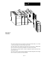
Hardware Overview ......................................................................... 1-2
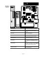
Hardware Features .......................................................................... 1-3
Getting
Started
Chapter 2..........................................................................................2-1
Getting Started ................................................................................ 2-1
Required Tools and Equipment ....................................................... 2-1
System Operation ............................................................................ 2-2
Resolver Wiring................................................................................ 2-2
Channel
Configuration,
Data and
Status
Chapter 3 ..........................................................................................3-1
Channel Configuration, Data and Status .......................................... 3-1
Module Addressing .......................................................................... 3-1
Resolver Module ID Code 3535..................................................... 3-1
Data Table Memory Map ................................................................. 3-1
Output Image ................................................................................ 3-1
Input Image ................................................................................... 3-2
Integer File .................................................................................... 3-3