1
Chapter
4
Step 3. Calibrate Resolver (Required for Slave Operation Only)
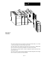
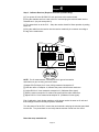
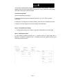
[a] Turn power off to the SLC500 PLC rack and remove the resolver board.
[b] Plug the extender card into a slot in the PLC rack and plug the resolver board into the
extender card. (Any slot except slot 0).
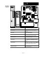
[c] Turn power back on to the PLC. Setup the resolver board for Slave operation by setting
switch S1.
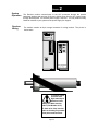
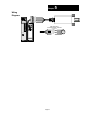
[d] Plug the cable from the resolver into the resolver module 8 pin connector according to
the tag on the module door.
S OC
REF
J4
J6
R25
(COS)
R24
R23 R22
(REF) (SIN)
J3
SIN
(MASTER)
REF
S1
(SLAVE)
51 R
(FORWARD)
S2
(REVERSE)
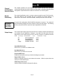
NOTE: For all measurements, use testpoint J6 for ground connection
and make sure you are using a true rms meter.
[f] Adjust R23 (Ref input) for 2 Vrms (2.8Vp) measured at testpoint J5.
[g] With the meter on testpoint J4, advance the press until the meter reads zero.
[h] Adjust R22 for 2 Vrms measured at testpoint J3. (Calibrates Sine signal).
[i] With the meter on testpoint J3, advance the press until the meter reads zero.
[j] Adjust R25 for 2 Vrms measured at testpoint J4. (Calibrates Cosine signal).
End of calibration, check display readings, verify degree readout is same on all units and
that readings increment correctly as press is advanced.
Turn the power off to the PLC, remove the card extender, and plug the resolver board back
into the slot. Turn power back on and verify that the resolver counts from 0 to 359.9.
Reset the setup mode bit to 0.
Page 4-3