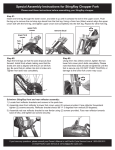
Download User and installation guide Steam Vac Classic
Transcript
25 5.1.2011 Steam V Vac Classic NTM/mfl User and installation n guide Steam Vac Classic – A proven steam m vacuum su uction tool fo or improved slaughter s hyggiene on Porrk,Beef and Sheep. Rem moves fat lum mps, bone frragments, haair, faecal and soiled carccass spots Easy , ergonomic and hygien nic to use Cleaans large areea Red duction of baacteria Imp proved micro obial and visu ual quality Technical d data: Scraaper blade: o Total sucction width Han ndle: Clip: m connection: o Vacuum o Steam connection: Totaal weight: Stainnless steel 60 m mm Polyyamid, PA – th hermoplast Stainnless steel Ø 322mm Ø 100 mm 463 gram Installation n advice and d dimension ning: DMRI has a attached general guidelines for use off Steam Vac Classic and connectionss to steam an nd vacuum. If more assista ance is requiired with spe ecific facility specifications s s DMRI offerrs specifications, dimensionin ng, steam an nd vacuum su upply, comm missioning, ap pprovals, traiining and conntrol after ind dividual customerr offers. Conttact Helge Møller M ph. +45 5 72202611 Mail: hmr@ @teknologisk..dk Contents: Useer manual o Replaceement of scraper blade o Cleaning procedure es nes for installation o Guidelin Connection and installinng of tool General guidelines for ssetup of vacu uum and stea am supply Prin ncipal diagraam for conne ecting the too ol to steam aand vacuum sup‐ ply.. How w to adjust the steam an nd vacuum suupply to a staandard user setting EC D Declaration o of a partly co ompleted maachinery and d safety evaluation Decclaration of ccompliance E EC 1935/20004 Material in nto contact w with food 1 User manual The Steam Vac Classic tool is developed for steam vacuum suction of warm carcasses. It is especially well suited for removal of fat lumps and bone fragments with the metal blade. It also removes contamination as an alternative to removal by knife and hands. After connection and correct setting of steam and vacuum the tool is used on contaminated areas to be treated. The tool is moved repeatedly over the contamination until it is removed. A short term reversible product discoloration is normal. Prolonged suction of an area may lead to irreversible product discoloration. By normal use discolorations rarely will occur after chilling of product. If the tool is blocked by fat or tissue this can be removed by an air pressure gun. Replacement of scraper blade If the stainless steel scraper blade needs replace follow procedure as described below: 1. After closing the steam and vacuum supply the tool is disconnected by removing the bracket split. 2. Remove the scraper blade carefully with set of pliers 3. Clean the handle 4. If there is dirt around or in the steam holes, use air pressure or a thin metal needle for remov‐ al 5. The new the scraper blade is carefully pressed in place by hand 6. Insert nozzles orientated correctly in the oval bracket openings 7. Connect the tool to the clip and secure the connection by inserting the split. 8. You can now start the work again. 2 Cleaning manual Cleaning during processing: The steam and vacuum supply to the steel scraper blade touching product keeps them continually sanitized. The tool may need a cleaning periodically depending on use. It can be cleaned with luke warm water at breaks (app. 42°C). At breaks also check for free passage in the head and handle and if blocked clean with an air pressure gun. In case of worn down scraper blade replace it. Cleaning after processing: Every day after processing the handle should be cleaned as follows: 1. Disconnect the handle by the bracket split 2. Use luke warm water (app.ca. 42°C) for cleaning inside and outside. Clean inside the handle as well as inside the nozzles 3. Disassemple the handle, bracket and nozzles by following instructions for nozzle replacement 4. Check for free passage in the steam channels and for wear on scraper blade. If steam chan‐ nels are blocked clean them with an air pressure gun or a metal needle. Worn down scraper blades should be replaced. 5. Place the handle in upright position in a dish washer and wash using a standard program app.60 ‐ 70°C. Standard programs should include pre rinsing, soap wash and after rinsing. Washing temperature depends on the soap tablet used, being either a alkali or acid based soap. Use of soap tablets as prescribed in the soap product‐sheet. 6. Handle is dried at room temperature. 7. Connect the handle to steam and vacuum by the bracket split In case of dried up contaminations on the handle or scraper blade soak in soap water. Use a 0,5 – 1% soap concentration or as prescribed in the data sheet for the soap product. Duration of soaking depends on degree of contaminations. After soaking place all part in the dishwasher as described above. Note!! It is important to soak in a soap solution and not in a detergent, as the soap will dissolve the dirt !!! 3 Guidelines for installation ale to be con nected with the purchasing parties ow wn existing or o for The Steam Vac Classic tool is for sa the purpose e new installe ed establishe ed supplies o of steam and d vacuum. As s use and seet up of the sy ystem will vary bettween differe ent slaughterrlines only ge eneral recom mmendations are given foor installation guidance. DMRI offerss further speccifications, dimensioning , steam and vacuum sup pply, commisssioning, app provals, training and d control after individual customer c offe ers. Contact Helge Møller ph. +45 722202611 Ma ail: hmr@tekno ologisk.dk Connection and installin ng of tool S Vac Tubular-5 T too ol must be of a quality suttied to come in direct con ntact The steam ssupplied to Steam with food. The steam a and vacuum hose must be b tightened securely on the stainless s steel clips w with hose clips, and conneccted to the ha andle with the split prior tto opening off steam and vacuum. Hoses shou uld be mountted and hung g in such a w way that they do not touch h the treated object durin ng steam vacuuming both while w the too ol is used or a at rest. Furth hermore the hose h should be mounted d in a manner thatt allows free movement for f the opera ator performin ng other task ks. A fork may be useful forr leaving the when at restt, see picture e. The placem ment of the ffork should be b selected in a w way that avoids the steam m fan to reacch products, the operatorr, or other byypassing ope erators in the area. A fork exam mple is shown n below ( in tthis case with h the Tubular-5 tool, but m may be similar). uidelines forr setup of va acuum and s steam supp ply: General gu Depending on setup, the e number of steam vac to ools used, diistances and d adjustment the installatiions may vary in specification n. Based on te ests with one e tool the con nsumption off steam is estimated to ap pprox. 10-200 kg steam/water/hour/tool. In some plants steam is a already available. When using an elecctrical steam m generator, an energy consu umption of ap pprox. 7-10 kkWh is expec cted. A vacuu um pump sysstem with se eparator providing g 5-15 kPa iss also neede ed and will re equire an add ditional energ gy consumpttion of approx. 4-6 kWh. Vacuu um pump typ pe and size will w depend o on demand and distance between pum mp and hand dle. Eg. a rotary lobe e blower with h a nominal motor m rating of 0,75 to 11 1 KW. That size s of pump is more than n sufficient; but it can be place ed far away from f the han ndle and still maintain vac cuum. Side cchannel blow wers can be used d, but care should be taken to avoid w water pocketts in the vacu uum hoses. In the attach hed diagram the needed componentss of a full sys stem is show wn in a generral design. DMRI offers to dim mension and specify indiv vidual solutio ons as a cons sultancy offe er. Kontakt Hellge Møller tlf. +45 722026 611 Mail: hm [email protected] 4 Needed general components are : Vacuum pump and valve Separator tank (any sealed container, where fat, dirt etc. can be separated from the airflow Water separator Steam supply, valve and manometer On/off Separator On/off Vacuum pump Steamegula tor Vacuum Water separator Steam Steam Manometer 1,2 bar Fat / dirt .. Handle Condensate Principal diagram for connecting the tool to steam and vacuum supply. How to adjust the steam and vacuum supply to a standard user setting Individual systems may need slightly different adjustment to be optimal. In the following a general simple procedure to adjust to at standard setting that has given good results is given. 1. Close of the vacuum, by closing the connection from handle to vacuum pump and water sepa‐ rator 2. Adjust the steam pressure to app. 1,2 bar on the outlet from the water separator (and pres‐ sure regulator) 3. Open connection (ball check valve) between the Water separator and steam vacuum handle – until there is a plume of steam “reaching” app. 1 meter from the nozzles 4. Open connection to vacuum pump (ball check valve) until the plume of steam reaches app. 2 cm from the nozzles. 5. Now try to operate the steam vacuum handle on product to be treated The above method is a basic setting. More vacuum can be needed. In that case the amount of steam will have to be increased also. 5 EC Declaration of a partly completed machinery and safety evaluation Steam Vac Classic is designed to become a part of a complete machine with connected steam and vacuum. As a partly completed machine it is declared constructed according to announcement No. 621 of 25. June 2008, that implements Directive 2006/42/EC. Risk evaluation is conducted according to ISO 14121-1. The risk profile is acceptable with a low probability of scalding by the operator unintentionally directing the steam fan towards own body or other operators nearby. Above partly completed machinery may not be taken into use, before the partly completed machine into which is been built in or to which purpose it must be used for, conform to any relevant regulations. Declaration of compliance EC 1935/2004 Material into contact with food Matherials used for manufacturing the Steam Vac Classic are intended to come into contact with food intended in compliance with regulations No. 1935/2004 EC. 6


