1
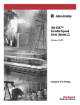
Technical Data
Bulletin 160
“Series C”
Smart Speed
Controllers
A Step Above the Rest…
Bulletin 160 Smart Speed Controller (SSC™)
with Sensorless Vector Performance
The Bulletin 160 Smart Speed Controller is available in models
rated between 0.37 to 4 kW (0.5 to 5 horsepower) with voltage
ratings 200-240V and 380-460V three-phase input and 0.37 to
1.5 kW (0.5 to 2 horsepower) 200-240V single phase input.
When the Bulletin 160 SSC was first introduced in the market,
its innovative design helped set the standard for future
microdrives. With the Series C design, expanded power ratings
(through 5 HP, 4 kW), increased functionality and an enhanced
hardware design place the Bulletin 160 SSC a “Step Above the
Rest” for small drive applications!
2
Bulletin 160 “Series C” Smart Speed Controller
with Sensorless Vector Performance
Technical Data
TABLE OF CONTENTS
Standard Drives Program
Description
Page
Catalog Number Description . . . . . . . . . . . . . . . . . . . . . 5
Product Selection . . . . . . . . . . . . . . . . . . . . . . . . . . . . . 5
Operator Interface & Communication Devices . . . . . . . 6
Accessories . . . . . . . . . . . . . . . . . . . . . . . . . . . . . . . . . . 7
Accessories and Repair Parts – Field Installed . . . . . . 8
Bulletin 160 Block Diagram . . . . . . . . . . . . . . . . . . . . . 10
Branch Circuit Block Diagram . . . . . . . . . . . . . . . . . . . 10
Specifications . . . . . . . . . . . . . . . . . . . . . . . . . . . . . . . 11
Approximate Dimensions . . . . . . . . . . . . . . . . . . . . . . 13
Communication Module Specifications . . . . . . . . . . . . 17
Display Parameter Descriptions . . . . . . . . . . . . . . . . . 17
Program Parameter Descriptions . . . . . . . . . . . . . . . . 18
Standard Drives Program – 160Z
Catalog Number Description . . . . . . . . . . . . . . . . . . . . 19
Product Selection . . . . . . . . . . . . . . . . . . . . . . . . . . . . 19
Operator Interface➀ & Communication Devices . . . . 20
Specifications . . . . . . . . . . . . . . . . . . . . . . . . . . . . . . . 21
Approximate Dimensions . . . . . . . . . . . . . . . . . . . . . . 23
Standard Packaged Drive Program
Ordering Instructions . . . . . . . . . . . . . . . . . . . . . . . . . . 24
Custom Configured Drives Program . . . . . . . . . . . . . . 24
Catalog Number Description . . . . . . . . . . . . . . . . . . . . 24
Product Selection . . . . . . . . . . . . . . . . . . . . . . . . . . . . 24
Factory Installed Enclosure Options . . . . . . . . . . . . . . 25
Option Rules . . . . . . . . . . . . . . . . . . . . . . . . . . . . . . . . 25
Approximate Dimensions for 160 NEMA Type 4/12 & 4X
Stainless Steel Enclosures . . . . . . . . . . . . . . . . . . . . . 26
3
Standard Drives Program
The 160 SSC (Smart Speed Controller) is a
compact variable speed drive for use on
three-phase induction AC motors. It is
microprocessor controlled and fully
programmable for a variety of applications.
Standard Features Include:
• Ratings of 0.37-4.0 kW (0.5-5 HP)
• Very Compact Design
• Feed Through Wiring
• IGBT Technology
• PWM Control
• Quiet Operation
• Programmable
Standard Drive Configurations:
• IP20 (Open Style)
• Chassis Mount
• 160Z (IP 65/NEMA 4X)
Standard Packaged Drives Available:
• IP66 (NEMA 4/12)
• IP66 (NEMA 4X)
Approvals:
• UL (UL 508C)
• C/UL (CSA 22.2)
• CE➀ EMC Directive (EMC: EN61800-3, EN50081-1,
EN50082-2)
Low Voltage Directive (LVD: EN50178, EN6024-1)
• C-Tick AS/NZS2064
➀ External components and proper guidelines must be
followed. Refer to the 160 User Manual for details.
Your order must include
• Catalog number of the drive
• If required, catalog number of any
accessories and/or factory installed
options.
4
Standard Drives Program
Catalog Number Description
160
Bulletin Number
– AA02
Drive Rating
(must be specified)
N
SF1
P1
Enclosure Rating
(must be specified)
Control Model
(must be specified)
Programmer
(optional)
Product Selection
Drive Ratings
Input Voltage
Rating
200-240V 50/60 Hz
Single-Phase
200-240V 50/60 Hz
Three-Phase
380-460V 50/60 Hz
Three-Phase
kW
0.37
0.55
0.75
1.5
0.37
0.55
0.75
1.5
2.2
4.0
0.37
0.55
0.75
1.5
2.2
4.0
HP
0.5
0.75
1
2
0.5
0.75
1
2
3
5
0.5
0.75
1
2
3
5
Output
Current Rating
2.3A
3.0A
4.5A
8.0A
2.3A
3.0A
4.5A
8.0A
12.0A
18.0A
1.2A
1.7A
2.3A
4.0A
6.0A
10.5A
IP 20 (Open Style)
Analog Signal Follower Model
Catalog Number ➀➂
160S - AA02NSF1
160S - AA03NSF1
160S - AA04NSF1
160S - AA08NSF1
160 - AA02NSF1
160 - AA03NSF1
160 - AA04NSF1
160 - AA08NSF1
160 - AA12NSF1
160 - AA18NSF1
160 - BA01NSF1
160 - BA02NSF1
160 - BA03NSF1
160 - BA04NSF1
160 - BA06NSF1
160 - BA10NSF1
Preset Speed Model
Catalog Number ➀➂
160S - AA02NPS1
160S - AA03NPS1
160S - AA04NPS1
160S - AA08NPS1
160 - AA02NPS1
160 - AA03NPS1
160 - AA04NPS1
160 - AA08NPS1
160 - AA12NPS1
160 - AA18NPS1
160 - BA01NPS1
160 - BA02NPS1
160 - BA03NPS1
160 - BA04NPS1
160 - BA06NPS1
160 - BA10NPS1
Output
Current Rating
2.3A
3.0A
4.5A
8.0A
2.3A
3.0A
4.5A
8.0A
12.0A
18.0A
1.2A
1.7A
2.3A
4.0A
6.0A
10.5A
IP 20 (Chassis Mount) ➁
Analog Signal Follower Model
Catalog Number ➀➂
160S - AA02PSF1
160S - AA03PSF1
160S - AA04PSF1
160S - AA08PSF1
160 - AA02PSF1
160 - AA03PSF1
160 - AA04PSF1
160 - AA08PSF1
160 - AA12PSF1
160 - AA18PSF1
160 - BA01PSF1
160 - BA02PSF1
160 - BA03PSF1
160 - BA04PSF1
160 - BA06PSF1
160 - BA10PSF1
Preset Speed Model
Catalog Number ➀➂
160S - AA02PPS1
160S - AA03PPS1
160S - AA04PPS1
160S - AA08PPS1
160 - AA02PPS1
160 - AA03PPS1
160 - AA04PPS1
160 - AA08PPS1
160 - AA12PPS1
160 - AA18PPS1
160 - BA01PPS1
160 - BA02PPS1
160 - BA03PPS1
160 - BA04PPS1
160 - BA06PPS1
160 - BA10PSP1
Drive Ratings
Input Voltage
Rating
200-240V 50/60 Hz
Single-Phase
200-240V 50/60 Hz
Three-Phase
380-460V 50/60 Hz
Three-Phase
kW
0.37
0.55
0.75
1.5
0.37
0.55
0.75
1.5
2.2
4.0
0.37
0.55
0.75
1.5
2.2
4.0
HP
0.5
0.75
1
2
0.5
0.75
1
2
3
5
0.5
0.75
1
2
3
5
➀ The Bulletin 160 comes standard with a Ready/Fault indication panel. To order a drive with a Program Keypad Module installed, add suffix “P1” to the catalog number.
For example: Catalog Number 160-AA02NSF1 becomes 160-AA02NSF1P1
➁ Meets IP54/65/66 (NEMA 12/4/4X) when installed in suitable enclosure.
➂ For pricing information refer to the Bulletin 160 Price Sheet.
5
Standard Drives Program
Operator Interface & Communication Devices
Accessory
Description
Ready/Fault Indicating Panel - Indicates if the drive is READY for operation or if a FAULT
condition has occurred. This module is provided as “standard equipment” when no other
factory installed options are ordered.
FAULT
READY
FAULT
READY
Remote
Programming
Adapter
Program Keypad Module - Provides the ability to program and/or monitor all drive parameters
as well as provide local keypad control (start, stop and reverse functions). See page 5,
Footnote 1, for information on how to order this option factory installed.
160-P1
Remote Keypad Module - Provides the ability to mount the operator interface remote from the
drive. A Remote Programming Adapter (160-RPA) and cable must be ordered separately.
160-P2
CopyCat Keypad Module - Provides the ability to program or monitor individual drive
parameters or upload and download all drive parameters. A Remote Programming Adapter
(160-RPA) and cable must be ordered separately.
160-P3
Remote Programming Adapter - Provides a simple interface connection for the Remote and
CopyCat Keypad Modules.
160-RPA
Cables - Connects the Remote Programming Adapter to either the Remote or CopyCat Keypad
Module. Several different cable lengths and types are available.
DeviceNet
FAULT
COMM
READY
Catalog
Number ➀
160-B1
Communications Module - Allows control and monitoring of parameters via the networks
listed below. These modules add 21.4 mm (0.85 in.) to the overall depth of the drive. See page
16 for dimensional information. Communication modules are as follows:
• DeviceNet
• RS232 Serial Communications
• Profibus
• Interbus
See page 8
160-DN2
160-RS1
160-PD1
160-IB1
DriveExplorer™ Software - Windows“ based software package that provides an intuitive means 9306-4KS0EFF
for monitoring or configuring Allen-Bradley drives and communications adapters.
➀ For pricing information refer to the Bulletin 160 Price Sheet.
6
Standard Drives Program
Accessories
Accessory
Ordering
Information
See Page 8
Dimension
Information
See Page 14
Capacitor Module - Provides extended ride through capability and increases
inherent braking performance. This module connects to the load side power
terminals marked DC- and DC+.
See Page 9
See Page 14
Line Filter Module - Reduces conductive emissions to meet EMC compliant
installations. The line filters are designed so that the drive can be mounted
on top (piggyback) of the line filter module to help reduce overall enclosure
size.
See Page 9
See Page 15
Line Reactor - Provides input power conditioning when installed on the line
side of the drive, or reflected wave protection when installed on the load side
of the drive. When used for reflected wave protection, the reactor should be
mounted close to the motor. Consult the 160 Drive User Manual for
recommendations on when to use this device.
See Page 8
See Page 15
RWR Module - Reduces potentially destructive reflected wave spikes that
can occur in applications with long cable distances between the drive and
motor. This device is designed for installation close to the output terminals
of the drive. Consult the 160 Drive User Manual for recommendations on
when to use this device.
See Page 8
See Publication
1204-5.1
24V DC Interface Module - Allows use of 24V DC “sink logic” control. Two
versions are available, one for preset speed models and one for analog signal
follower models. The 24V DC interface attaches directly to the drives'
control terminal block.
See Page 8
No added panel
space is
necessary with
this device.
Description
Dynamic Brake Module - Provides external dynamic braking capability for
applications with a duty cycle rating not exceeding 5%. Parameter 52 (DB
Enable) must be set to 5% to achieve this performance level. For
applications greater than 5%, a resistor package must be properly sized to
avoid overheating.
7
Standard Drives Program
Accessories and Repair Parts – Field Installed
Accessories
Catalog Number
160-DM-SF1➀
160-DM-PS1➀
160-C10R
160-C10
160-C30
160-C50
1321-M001
1321-M009
Repair Parts
Description ➅
24V DC Interface (Analog Model)
24V DC Interface (Preset Model)
1.0 m (3.3 ft.) Cable w/ right angle connector
1.0 m (3.3 ft.) Cable
3.0 m (9.8 ft.) Cable
5.0 m (16.4 ft.) Cable
Ferrite core (unwound)
Ferrite core (wound)
Drive Ratings
Input Voltage
Rating
200-240V,
50/60 Hz,
Single-Phase
200-240V,
50/60 Hz,
Three-Phase
380-460V,
50/60 Hz,
Three-Phase
➀
➁
➂
➃
kW
0.37
0.55
0.75
1.5
0.37
0.55
0.75
1.5
2.2
4.0
0.37
0.55
0.75
1.5
2.2
4.0
HP
0.5
0.75
1
2
0.5
0.75
1
2
3
5
0.5
0.75
1
2
3
5
Catalog Number
160-FRK1
160-FRK2
160-FRK3
Description ➅
Fan Replacement Kit, 0.75-2.2 kW (1-3 HP) for Series A or B drives
Fan Replacement Kit, 0.75-2.2 kW (1-3 HP) for Series C drives
Fan Replacement Kit, 4 kW (5 HP) for Series C drives
Dynamic Brake Module
Line Reactors - Open Style
RWR Module
Catalog Number ➅
–
–
160-BMA1
160-BMA2
–
–
160-BMA1
160-BMA2
160-BMA2
160-BMA2 ➂
–
–
160-BMB1
160-BMB2
160-BMB2
160-BMB2 ➂
Catalog Number ➁➅
–
–
–
–
1321-3R4-B
1321-3R4-A
1321-3R4-A
1321-3R8-A
1321-3R12-A
1321-3R18-A
1321-3R2-B
1321-3R2-A
1321-3R2-A
1321-3R4-B
1321-3R8-B
1321-3R18-B
Catalog Number ➃➅
–
–
–
–
–
–
–
–
–
–
1204-RWR2-09-B
1204-RWR2-09-B
1204-RWR2-09-B
1204-RWR2-09-B
1204-RWR2-09-B
1204-RWR2-09-B ➄
Series B 24V Interface Modules are required for use with Series C Drives.
Catalog numbers listed are for 3% impedance open style units. NEMA Type 1 and 5% impedance reactor types are also available, refer to publication 1321-2.0.
TWO UNITS MUST BE USED, wired in parallel.
Refer to Publication 1204-5.1 for dimensional information on RWR Devices.
➄ The 1204-RWR2-09-B may be used at a 10.5 Amp current rating providing the cable length from drive to motor is less than 122 meters (400 feet).
➅ For pricing information refer to the Bulletin 160 Price Sheet.
8
Standard Drives Program
Accessories and Repair Parts – Field Installed
Drive Ratings
Input Voltage
Rating
200-240V,
50/60 Hz,
Single-Phase
200-240V,
50/60 Hz,
Three-Phase
380-460V,
50/60 Hz,
Three-Phase
kW
0.37
0.55
0.75
1.5
0.37
0.55
0.75
1.5
2.2
4.0
0.37
0.55
0.75
1.5
2.2
4.0
HP
0.5
0.75
1
2
0.5
0.75
1
2
3
5
0.5
0.75
1
2
3
5
“LF” Line Filter Module
“RF” Line Filter Module
Capacitor Module
Catalog Number ➀➂➃
160S-LFA1
160S-LFA1
160S-LFA1
160S-LFA1➄
160-LFA2
160-LFA2
160-LFA2
160-LFA2
160-LFA2
–
160-LFB1
160-LFB1
160-LFB1
160-LFB1
160-LFB1
–
Catalog Number ➁➂➃➅
160S-RFA-9-A
160S-RFA-9-A
160S-RFA-9-A
160S-RFA-16-B
160-RFB-5-A
160-RFB-5-A
160-RFB-5-A
160-RFB-14-A
160-RFB-14-A
160-RFA-22-B
160-RFB-5-A
160-RFB-5-A
160-RFB-5-A
160-RFB-5-A
160-RFB-14-A
160-RFB-14-B
Catalog Number ➂
160-CMA1
160-CMA1
160-CMA1
160-CMA1
160-CMA1
160-CMA1
160-CMA1
160-CMA1
160-CMA1
160-CMA1
160-CMB1
160-CMB1
160-CMB1
160-CMB1
160-CMB1
160-CMB1
➀ The 160LF type filters have been tested with a maximum motor cable length of 75 meters (246 feet) for 230V units and 40 meters (131 feet) for 460V units. Refer to
the 160 User Manual (publication 0160-5.15) for detailed installation considerations.
➁ The 160RF type filters have been tested with a maximum motor cable length of 25 meters (82 feet) for both 230V and 460V units. Refer to the 160 User Manual for
more detailed installation considerations.
➂ For pricing information refer to the Bulletin 160 Price Sheet.
➃ Bulletin 160 Series C drives (with proper filter) meet:
– Overall EMC requirements of EN61800-3 for Second (Industrial) Environments
– High frequency conducted and radiated emissions of EN61800-3 for (First) Residential Environments
– High frequency conducted and radiated emissions of EN55011 for (Second) Industrial Environments
➄ Must mount separately when used with Series C drives.
➅ Must be used with Series C drives.
9
Standard Drives Program
Bulletin 160 Block Diagram
Capacitor Module
Brake Module
BR+
BR–
DC+
DC–
L1/R
T1/U
L2/S
T2/V
L3/T
Frequency Reference
Preset Speed Model
TB3 -1
TB3 -2
TB3 -3
GND/PE
Analog Model
TB3-1
–10V to +10V
or
Potentiometer
or
4-20 mA
TB3-2
TB3 -4
Reverse
Start
Programmable Input
Common
Motor
T3/W
Control
Power
Bus
Voltage
Circuitry
TB3-3
(Common)
GND/PE
Current
Circuitry
Fault Feedback
TB3-4
CPU
Program
Keypad
Module
TB3-5
TB3-6
TB3-8
TB3-7
Opto
Isolator
Relay
Circuitry
TB3-9
TB3-10
TB3-11
User
Programmable
Output
Branch Circuit Block Diagram
Short circuit and overload protection are requirements of any motor branch circuit.
Input power conditioning, CE conformance, motor cable length and motor cable type
(reflected wave and capacitive current coupling considerations) are important
considerations of drive applications.
Branch Circuit Protective Devices
(Consult the 160 User Manual)
Input Power Conditioning – See Line Reactor on page 7
Line (EMC) Filter – See page 7
Dynamic Brake Module – See page 7
R/L1 S/L2 T/L3 BR– BR+
Operator Interface or Communication Module –See page 6
ESC SEL
1 2 3 4 5 6 7 8 9 10 11
U/T1 V/T2 W/T3 DC– DC+
Capacitor Module – See page 7
Reflected Wave Protection – See Line Reactor or RWR Module on page 7
Motor Cable Type and Length Recommendations –
(Consult the 160 User Manual)
Class 10 Overload Protection – provided by the 160 drive
Motor – See publication 1329R-1.0
10
Standard Drives Program
Specifications
Drive Ratings
IP20 Catalog Number
Single-Phase
Input, 50/60 Hz
200 - 240V
160S-AA02
160S-AA03
160S-AA04
160S-AA08
–
–
380 - 460V
–
–
–
–
–
–
Output Ratings
Input Ratings
Three-Phase
Input, 50/60 Hz
kW
HP
Output
Current
Operating
Voltage Range
kVA
Dynamic Braking Torque
Without
With
External
External
Resistor
Resistor
Power Dissipation
160-AA02
160-AA03
160-AA04
160-AA08
160-AA12
160-AA18
0.37
0.55
0.75
1.5
2.2
4.0
0.5
0.75
1
2
3
5
2.3A
3.0A
4.5A
8.0A
12.0A
18.0A
180-265V
180-265V
180-265V
180-265V
180-265V
180-265V
1.4
1.8
2.7
4.0
7.1
10.6
100%
100%
100%
50%
50%
20%
–
–
200%
150%
115%
100%
20W
25W
35W
74W
107W
137W
4W
5W
10W
15W
20W
–
160-BA01
160-BA02
160-BA03
160-BA04
160-BA06
160-BA10
0.37
0.55
0.75
1.5
2.2
4.0
0.5
0.75
1
2
3
5
1.2A
1.7A
2.3A
4.0A
6.0A
10.5A
340-506V
340-506V
340-506V
340-506V
340-506V
340-506V
1.4
2.0
2.7
4.7
7.1
12.3
100%
100%
100%
50%
50%
20%
–
–
200%
150%
115%
100%
25W
30W
37W
50W
77W
120W
4W
5W
8W
15W
20W
–
IP20
(Open Style)
IP 20
(Chassis Mount)
Input/Output Ratings (All Drive Ratings)
Output Voltage
Adjustable from 0V to input voltage
Output Frequency
0 to 240 Hz - Programmable
Efficiency
97.5% (Typical)
Transient Protection
Standard 6kV (Series C drives)
Environmental Specifications (All Drive Ratings)
Enclosure
IP 20/IP66 (NEMA Type 12/4/4X)
Ambient Temperature
IP 20
IP 66 (NEMA Type 12/4/4X)
0 to 50 degrees C (32 to 122 degrees F)
0 to 40 degrees C (32 to 104 degrees F)
Storage Temperature
–40 to 85 degrees C (–40 to 185 degrees F)
Relative Humidity
0 to 95% (non condensing)
Vibration
1.0 G Operational - 2.5 G Non-operational
Shock
15 G Operational - 30 G Non-operational
Altitude
1,000 meters (3,300 feet) without derating
Control Inputs
Control Input Type
For dry contact closure input - drive has an internal 12V power supply that provides10mA (typical) current.
Also accepts open collector/solid-state input with maximum leakage current of 50µA. Optional 24V DC interface
allows use of 24V DC “sink logic” inputs.
Start, Stop, Forward/Reverse
Configurable inputs for 2 or 3 wire control
Control Inputs (Analog Signal Follower Model Only)
Analog Input (4 to 20mA)
Input impedance 250 ohms
Analog Input (-10 to +10V DC)
Input impedance 100k ohms
External Speed Potentiometer
1k to 10k ohms, 2 Watt minimum
PI Control
Parameter 46, setting 9 provides PI Control function
SW1, SW2
Parameter 46, setting 8 provides 4 preset speeds and 2 accel/decel times
11
Standard Drives Program
Specifications, Continued
Control Inputs (Preset Speed Model Only)
SW1, SW2, SW3
Configurable inputs for control of 8 preset speeds and 2 accel/decel times
Control Output
Programmable Output
(form C relay contact)
Resistive Rating: 0.4A at 125V AC, 0.2A at 230V AC, 2A at 30V DC
Inductive Rating: 0.2A at 125V AC, 0.1A at 230V AC, 1A at 30V DC
Programmable for eleven different functions
Control Features
PWM Algorithm
Sine weighted PWM with harmonic compensation
Switching Device (3-Phase Output)
IGBT (Insulated Gate Bipolar Transistor)
V/Hz Ratio
Programmable
Carrier Frequency
Adjustable from 2 kHz to 8 kHz in 100 Hz increments (factory default is 4 kHz)
DC Boost
Adjustable - Select from a family of boost curves
Current Limiting
Trip free operation, coordinated for drive and motor protection. Programmable from 1% to 180% of drive Output Current.
Motor Protection
I2t overload protection - 150% for 60 seconds, 200% for 30 seconds (Provides Class 10 overload protection)
Overload Pattern #0
Flat response over speed range (no speed compensation)
Overload Pattern #1
Speed compensation below 25% of base speed
Overload Pattern #2
Speed compensation below 100% of base speed
Acceleration/Deceleration Time(s)
0.1 to 600 seconds
S-Curve Accel/Decel Time(s)
0 to 100% of accel/decel time - not to exceed 60 seconds
Stopping Modes
4 modes (programmable)
Ramp to Stop
0.1 to 600 seconds
Coast
Stops all PWM output
DC Injection Brake
Applies DC voltage to the motor for 0 to 25 seconds
DC Injection Braking w/ Auto Stop
Applies DC voltage to the motor for 0 to 25 seconds with Auto Shutoff
Protective Features
Overcurrent
200% hardware limit, 300% instantaneous fault
Excessive Temperature
Embedded temperature sensor trips if heatsink temperature exceeds 95 degrees C (203 degrees F)
Over Voltage
Drive Rated Input = 200-240V AC
Drive Rated Input = 380-460V AC
DC Bus voltage is monitored for safe operation
Overvoltage trip occurs at 400V DC bus voltage (equivalent to 290V AC incoming line voltage).
Overvoltage trip occurs at 800V DC bus voltage (equivalent to 575V AC incoming line voltage).
Under Voltage
Drive Rated Input = 200-240V AC
Drive Rated Input = 380-460V AC
DC Bus voltage is monitored for safe operation
Undervoltage trip occurs at 210V DC bus voltage (equivalent to 150V AC incoming line voltage).
Undervoltage trip occurs at 390V DC bus voltage (equivalent to 275V AC incoming line voltage).
Control Ride Through
Minimum ride through is 0.5 seconds - typical value 2 seconds
Ground Fault
Protection in both Start and Run Mode
Faultless Ride Through
100 milliseconds
Output Short Circuit
Any output phase to phase short
Programming
Programmer / Display Type
Program Keypad Module - 6 character LED display
Remote Keypad Module - 4 character LED display
CopyCat Keypad Module - 2 line, 16 character LCD display
Local Controls
SPEED, RUN, STOP, and DIRECTION controls
12
Standard Drives Program
Analog Signal Follower and Preset Speed Models - Approximate Dimensions
Dimensions are shown in millimeters (inches). Dimensions are not to be used for manufacturing purposes.
0.37 kW-2.2 kW (0.5-3 HP), Three-Phase, 200-240V AC & 380-460V AC
0.37 kW-0.75 kW (0.5-1 HP), Single-Phase, 200-240V AC
Mounting Holes
4.5 (0.18) - 4 Places
Approximate Weight is 0.94 kg (2.07 lbs.)
80.0 (3.15)
165.4 (6.51)
60.0 (2.36)
60.0
(2.36)
R/L1 S/L2 T/L3 BR– BR+
130.0
(5.12)
83.3
(3.28)
ESC SEL
152.0
(6.00)
1 2 3 4 5 6 7 8 9 10 11
U/T1 V/T2 W/T3 DC– DC+
28.2
(1.11)
101.9 (4.01)
60.0 (2.36)
4.0 kW (5 HP), Three-Phase, 200-240V AC & 380-460V AC
1.5 kW (2 HP), Single-Phase, 200-240V AC
Approximate Weight is 2.37 kg (5.23 lbs.)
92.0 (3.62)
Mounting Holes
5.5 (0.22) - 4 Places
81.0 (3.19)
193.3 (7.61)
60.0 (2.36)
129.8 (5.11)
R/L1 S/L2 T/L3 BR– BR+
180.1
(7.09)
ESC SEL
192.5
(7.58)
111.5
(4.39)
1 2 3 4 5 6 7 8 9 10 11
U/T1 V/T2 W/T3 DC– DC+
39.1
(1.54)
60.0 (2.36)
*
NOTE: 12.7 mm (0.50 in.) is required around the top, bottom and front of all drives. No clearance is required between drives with the exception of the 2.2 kW (3 HP)
rating which requires 8.4 mm (0.33 in.).
13
Standard Drives Program
Approximate Dimensions, Continued
Dimensions are shown in millimeters (inches). Dimensions are not to be used for manufacturing purposes.
Chassis Mount, All Ratings
Approximate Weight is 7.26 kg (16 lbs.) through 1.5 kW (2 HP) and 7.71 kg (17 lbs.) for 2.2 kW (3 HP)
Rating
Width
0.37-.75 kW (0.5-1 HP)
0.37-1.5 kW (0.5-2 HP)
2.2 kW (3 HP)
1.5 kW (2 HP)
4.0 kW (5 HP)
130.1 (5.12)
114.1 (4.49)*
Width
1
3
3
1
3
175.0 (6.84)
175.0 (6.89)
244 (9.61)
244 (9.61)
244 (9.61)
112.0 (4.41)
140.0 (5.51) w/DeviceNet Module
98.0 (3.86)
97.5
(3.84)
Phase
Depth
54.7 (2.15)
54.7 (2.15)
63.12 (2.48)
96 (3.78)
96 (3.78)
Depth
R/L1 S/L2 T/L3 BR– BR+
195.1
(7.68)
179.1
(7.05)*
210.0
(8.27)
ESC SEL
210.1
(8.27)
1 2 3 4 5 6 7 8 9 10 11
U/T1 V/T2 W/T3 DC– DC+
*Cutout Dimension
Customer Panel
5.0 (0.20) Diameter - 6 Places
Dynamic Brake Module
71.2
(2.83)
48.2
(1.97)
Capacitor Module
8.0
(0.32)
13.9
(0.55)
86.4
(3.40)
50.0
(1.97)
40.0
(1.57)
7.5 (0.30)
4.5 (0.18) Dia. - 4 Places
110.9
(4.37)
WARNING
140.0
(5.51)
A
B
150.9
(5.94)
130.0
(5.11)
DANGER
+ –
GND BR BR
27.9
(1.14)
5.8 (0.23) Dia.
4 Places
Catalog Number
A
160-BMA1, -BMB1 245.0 (9.64)
160-BMA2, -BMB2 334.0 (13.15)
14
254.0 (10.00)
Approximate Lead Length
11.9
(0.47)
B
225.0 (8.86)
314.0 (12.36)
Standard Drives Program
Approximate Dimensions, Continued
Dimensions are shown in millimeters (inches). Dimensions are not to be used for manufacturing purposes.
Line Reactor
Catalog
Number
1321-3R2-A
1321-3R2-B
1321-3R4-A
1321-3R4-B
1321-3R8-A
1321-3R8-B
1321-3R12-A
1321-3R18-A
1321-3R18-B
A
B
E
D
C
A
112 (4.40)
112 (4.40)
112 (4.40)
112 (4.40)
152 (6.00)
152 (6.00)
152 (6.00)
152 (6.00)
152 (6.00)
B
104 (4.10)
104 (4.10)
104 (4.10)
104 (4.10)
127 (5.00)
127 (5.00)
127 (5.00)
133 (5.25)
133 (5.25)
C
74 (2.90)
74 (2.90)
76 (3.00)
76 (3.00)
76 (3.00)
76 (3.00)
76 (3.00)
79 (3.10)
86 (3.40)
D
50 (1.98)
50 (1.98)
50 (1.98)
50 (1.98)
53 (2.10)
53 (2.10)
53 (2.10)
51 (2.00)
63 (2.48)
E
37 (1.44)
37 (1.44)
37 (1.44)
37 (1.44)
51 (2.00)
51 (2.00)
51 (2.00)
51 (2.00)
51 (2.00)
Line Filter Module
D
60.0
(2.36)
C
200.0 (7.87)
Approximate
Lead Length
F
A
B
Catalog Number A
160S-RFA-9-A
182
(7.17)
160-RFB-5-A
182
(7.17)
160-RFB-14-A
182
(7.17)
160-RFB-14-B
227
160-RFA-22-B
(8.94)
160-RFA-16-B
160S-LF (All)
174
160-LF (All)
(6.85)
B
163
(6.42)
163
(6.42)
163
(6.42)
212
(8.35)
C
37.5
(1.47)
37.5
(1.47)
47.5
(1.87)
55.5
(2.18)
D
75
(2.95)
75
(2.95)
75
(2.95)
87
(3.43)
E
M4.5 x 6.5
(0.18 x 0.26)
M4.5 x 6.5
(0.18 x 0.26)
M4.5 x 6.5
(0.18 x 0.26)
M4.5
(0.18)
F
6.6 x 4.5
(0.26 x 0.18) 2 Places
6.6 x 4.5
(0.26 x 0.18) 2 Places
6.6 x 4.5
(0.26 x 0.18) 2 Places
6.6 x 4.5
(0.26 x 0.18) 2 Places
163
(6.42)
50.0
(1.97)
75
(2.95)
6.9 x 5.3
7.0 x 5.3
(0.27 x 0.21) (0.28 x 0.21)
E
Three-Phase filter shown (single-phase filter is the same size)
15
Standard Drives Program
Approximate Dimensions, Continued
Dimensions are shown in millimeters (inches). Dimensions are not to be used for manufacturing purposes.
DeviceNet and RS-232 Module
MADE IN U.S.A.
SER
67.5
(2.68)
RS232
Serial Comm
READY
CAT
COMM
➀ Required for module removal.
➁ Module adds this dimension to the overall drive depth.
160-RS1
FAULT
➁
21.4
(0.85)
➀
17.34
(0.68)
70.0
(2.76)
Remote Keypad Module
35.1
(1.38)
11.4
(0.45)
128.5
(5.06)
5.0
(0.20)
100.0
(3.94)
7.5
(0.30)
90.0
(3.54)
168.1
(6.62)
129.3
(5.09)
PROGRAM
ESC
RUN
FORWARD
REVERSE
70.0
(2.76)
135.0
(5.32)
SEL
140.0
(5.51)
3.0 (0.12) maximum thickness
4.0 (0.16) diameter, 6 places
16
Standard Drives Program
Communication Module Specifications
Specification
Electrical
Supply Voltage
Power Consumption
Network Input Current
DeviceNet (160-DN2)
RS232 (160-RS1)
Profibus (160-PD1)
Interbus (160-IB1)
Network Supply Voltage 11-25V DC
1 Watt
40 mA Maximum
Supplied by drive
1.25 Watts Maximum
NA
Supplied by drive
1.25 watts maximum
NA
Supplied by drive
1.25 watts maximum
NA
125, 250, 500 KBPS
NA
DeviceNet
No
No
Yes
Yes
No
Yes
NA
1200, 2400, 4800, 9600 BPS
BCC or CRC
DF1 Point to Point, DF1 Multidrop
NA
NA
NA
NA
NA
NA
NA
Autobaud 9.Kb to 12Mb
NA
Profibus -DP
NA
NA
NA
NA
No
Yes
Yes
500Kb
NA
Interbus S DRIVECOM 20 (21)
NA
NA
NA
NA
No
Yes
Yes
0 to 50 degrees C (32 to 122 degrees F)
–40 to 85 degrees C (–40 to 185 degrees F)
0 to 95% non-condensing
1.0 G Operational, 2.5 G Non-Operational
15.0 G Operational, 30.0 G Non-Operational
1,000 meters (3,300 feet) without derating
0 to 50 degrees C (32 to 122 degrees F)
–40 to 85 degrees C (–40 to 185 degrees F)
0 to 95% non-condensing
1.0 G Operational, 2.5 G Non-Operational
15.0 G Operational, 30.0 G Non-Operational
1,000 meters (3,300 feet) without derating
0 to 50 degrees C (32 to 122 degrees F)
–40 to 85 degrees C (–40 to 185 degrees F)
0 to 95% non-condensing
1.0 G Operational, 2.5 G Non-Operational
15.0 G Operational, 30.0 G Non-Operational
1,000 meters (3,300 feet) without derating
0 to 50 degrees C (32 to 122 degrees F)
–40 to 85 degrees C (–40 to 185 degrees F)
0 to 95% non-condensing
1.0 G Operational, 2.5 G Non-Operational
15.0 G Operational, 30.0 G Non-Operational
1,000 meters (3,300 feet) without derating
Communications
Baud Rates
CheckSum
Protocol
Explicit Peer-to-Peer Messaging
I/O Peer-to-Peer Messaging
Configuration Consistency Value
Faulted Node Recovery
Master/Scanner
I/O Slave Messaging
Slave Telegram
Environmental
Ambient Operating Temperature
Ambient Storage Temperature
Relative Humidity
Vibration
Shock
Vibration
Display Parameter Descriptions
Parameter Number
1
2
3
4
5
6
7
8
9
10
11
12
13
14
15
16
17
18
19
Parameter Name
Output Frequency
Output Voltage
Output Current
Output Power
Bus Voltage
Frequency Command
Last Fault
Heatsink Temperature
Controller Status
Controller Type
Control Version
Input Status
Power Factor Angle
Memory Probe Display
Preset Status
Analog Input
Fault Buffer 0
Fault Buffer 1
Fault Buffer 2
Description
0.0 to 240.0 Hz
0 to max voltage
0 to 2 times drive rated output current in units of 0.01A
0 to 2 times drive rated output power in units of 0.01kW
0V to 410V for 230V controllers, 0V to 815V for 460V controllers
0.0 to 240.0 Hz
Retains faults for troubleshooting
69 to 150 degrees C (156 to 302 degrees F)
Running, forward, accelerating, decelerating
Used by Rockwell Automation field service personnel
Displays firmware version
Displays the status of start, stop, and reverse discrete inputs
0.0 to 90.0 degrees
Used by Rockwell Automation field service personnel
Displays the status of preset speed discrete inputs
Displays the analog input as a percent of full scale
Stores the last fault that occurred
Stores the second most recent fault that occurred
Stores the third most recent fault that occurred
Units
0.1 Hz
1 Volt
0.01 Amps
0.01 kW
1 Volt
0.1 Hz
Numeric Value
1 Degree C
Binary Number
Numeric Value
Numeric Value
Binary Number
0.1 Degrees
Numeric Value
Binary Number
0.1%
Numeric Value
Numeric Value
Numeric Value
17
Standard Drives Program
Program Parameter Descriptions
Parameter Number
30
31
32
33
34
35
36
37
38
39
40
41
42
43
44
45
46
47
48
49
50
51
52
53
54
55
56
57
58
59
60
61
62
63
64
65
66
67
68
69
70
71
72
73
74
75
76
78
79
80
81
82
83
84
18
Parameter Name
Accel Time 1
Decel Time 1
Minimum Frequency
Maximum Frequency
Stop Mode Select
Base Frequency
Base Voltage
Maximum Voltage
Boost Select
Skip Frequency
Skip Frequency Band
Motor Overload Select
Motor Overload Current
Current Limit
DC Hold Time
DC Hold Voltage
Input Mode
Output Configure
Output Threshold
PWM Frequency
Restart Tries
Restart Time
DB Enable
S-Curve
Clear Fault
Memory Probe Address
Reset Functions
Program Lock
Internal Frequency
Frequency Select
Zero Offset
Preset Frequency 0
Preset Frequency 1
Preset Frequency 2
Preset Frequency 3
Preset Frequency 4
Preset Frequency 5
Preset Frequency 6
Preset Frequency 7
Accel Time 2
Decel Time 2
IR Compensation
Slip Compensation
Reverse Disable
Analog Select
Analog Input Minimum
Analog Input Maximum
Compensation
Software Current Trip
Stall Fault Time
PI Proportional Gain
PI Integral Gain
PI Process Reference
PI Dead Band
Description
0.0 to 600.0 seconds
0.1 to 600.0 seconds
0 to 240 Hz
0 to 240 Hz
Four settings - Ramp, Coast, DC injection braking, DC Injection w/ auto shut off
10 to 240 Hz
20 to 230V for 230V drives, 20 to 460V for 460V drives
20 to 255V for 230V drives, 20 to 510V for 460V drives
8 boost settings, 4 fan/pump curves
0 to 240 Hz
0 to 30 Hz
Three settings - No derating, Min derating, Max derating
25 to 200% of drive rated current in units of 0.01 amps
1 to 180% of drive rated current
0 to 25 seconds
0 to 115V
Configurable terminal block provides 10 different control schemes
11 different settings for a variety of drive status conditions
0 to 815
2.0 to 8.0 kHz
0 to 9
0.5 to 300.0 seconds
Used to set percent duty cycle for external dynamic braking
0 to 100% accel/decel smoothing
Resets faults
Used by Rockwell Automation personnel
Used to reset drive to factory default settings or update input mode
Protects user settings
0.0 to 240.0 Hz
Selects source of frequency (internal or external)
Used to add or subtract any system offset to analog input
0.0 to 240.0 Hz
0.0 to 240.0 Hz
0.0 to 240.0 Hz
0.0 to 240.0 Hz
0.0 to 240.0 Hz
0.0 to 240.0 Hz
0.0 to 240.0 Hz
0.0 to 240.0 Hz
0.1 to 600.0 seconds
0.0 to 600.0 seconds
0 to 150%
0.0 to 5.0 Hz
Disables Reverse Input
Used to select between unipolar and bipolar inputs
Sets the percent of analog input to represent Minimum Frequency
Sets the percent of analog input to represent Maximum Frequency
Compensates for Motor Instability or Resonance
Software instantaneous current trip
Selects amount of time the drive is in a stall condition prior to a fault occurring
Proportional Response of PI Regulator
Integral Gain of PI Regulator
PI will regulate to this setpoint value
PI will ignore errors less than this value
Factory Default
10.0
10.0
0
60
Ramp
60
230/460
230/460
2
240
0
No derating
115
150
0.0
0
Three-wire
0
0
4.0
0
10.0
Disable
0
0
0
0
0
60
External
0
3
20
30
40
45
50
55
60
20
20
50
2
0
0
0
100
0
0
0
0.01
0.01
0
0
Standard Drives Program – 160Z
Catalog Number Description
160Z –
Bulletin
Number
AA02
F
S
N
N➀
N
Drive Rating
(must be specified)
Enclosure Rating
(must be specified)
Control Method
(must be specified)
Filter Option
(must be specified)
Communication
(Future Option)
Motor
(Optional)
Product Selection
Drive Rating
Input Voltage Rating
200-240V,
50/60 Hz,
Three-Phase
380-460V,
50/60 Hz,
Three-Phase
kW
0.37
0.55
0.75
1.5
2.2
0.37
0.55
0.75
1.5
2.2
4
HP
0.5
0.75
1
2
3
0.5
0.75
1
2
3
5
Catalog Number
Output Current
Rating
2.3A
3A
4.5A
8A
12A
1.2A
1.7A
2.3A
4A
5.2A
8.1A
without Motor➁
160Z-AA02FSNNN
160Z-AA03FSNNN
160Z-AA04FSNNN
160Z-AA08FSNNN
160Z-AA12FSNNN
160Z-BA01FSNNN
160Z-BA02FSNNN
160Z-BA03FSNNN
160Z-BA04FSNNN
160Z-BA06FSNNN
160Z-BA10FSNNN
with Integral CE Filter
—
—
—
—
—
160Z-BA01FSFNN
160Z-BA02FSFNN
160Z-BA03FSFNN
160Z-BA04FSFNN
160Z-BA06FSFNN
160Z-BA10FSFNN
➀ When using 160Z as wall mount, communication modules should be ordered as separate options. See page 20.
➁ For 160Z drives mounted on motors, consult factory.
19
Standard Drives Program – 160Z
Operator Interface➀ & Communication Devices
Accessory
Remote Keypad
Module
160-P2
CopyCat Keypad Module
Hand held module with upload/download capability to program, monitor and control
drive.
CopyCat Keypad
Module
160-P3
DeviceNet
FAULT
READY
COMM
RS232
Serial Comm
FAULT
READY
COMM
FAULT
DeviceNet
Communication Module
160-DN2
RS-232 Serial
Communication Module
160-RS1
Profibus
Communication Module
160-PD1
READY
COMM
Profibus-DP
Interbus
Communication Module
160-IB1
TR
FLT RD
InterBus
➅
20
160-P3
Cables ➁
Connects the 160Z to either the Remote or CopyCat Keypad Module.
- 1 meter cable, locking each end
- 3 meter cable, locking each end
- 5 meter cable, locking each end
160Z-C10
160Z-C30
160Z-C50
Communication Modules and Accessories
Allow control and monitoring of parameters via the networks listed below. These
modules can be mounted inside the 160Z.
- DeviceNet™
- RS-232 Serial Communication
- Profibus
- Interbus
- RS232 Communication Terminal Block
- Profibus Communication Terminal Block
- Interbus In/Out Communication Terminal Block
- Interbus Side Metal plate (5 holes)
160-DN2 ➂
160-RS1
160-PD1
160-IB1
160Z-RTB
160Z-PTB
160Z-ITB
160Z-ISM
Motor Adapters
- NEMA motor, 0.5 - 2 HP ➃
- NEMA motor, 3 - 5 HP ➃
- SEW, IEC Motor, 0.37-1.5 kW ➄
- SEW, IEC Motor, 2.2 kW ➄
- SEW, IEC Motor, 3.7 kW ➄➅
160Z-ABN1
160Z-ABN2
160Z-SEW1
160Z-SEW2
160Z-SEW3
Hardware
- Power cable glands
- Motor cable glands, wall mounting only
- Communication and I/O cable glands
160Z-G25
160Z-G20
160Z-G16
Accessories
- Debris cover, motor mount
- Debris cover, wall mount
- Fan replacement kit
- Spare gasket kit (includes all gaskets)
- Wall mounting kit (includes one 160Z-G20)
- Wall mount adapter
160Z-DC
160Z-DCW
160Z-FRK
160Z-GSK
160Z-WMK
160Z-WMA
DriveExplorer™ Software
Windows based software package that provides an intuitive means for monitoring or
configuring Allen-Bradley drives and communication adapters.
CC BA
Catalog No.
Remote Keypad Module
160-P2
Module for remote mounting. Has program, monitor and operator interface capability.
➀
➁
➂
➃
➄
See Publication 9306PL001A-EN-P.
160-P1 is not compatible with 160Z drives.
160-RPA is not required with 160Z drives. 160-RPA circuitry is included as standard.
Includes 10 pin DeviceNet Connector.
For mounting with Allen-Bradley 1329RS motors, cast iron, severe duty.
For mounting with SEW, D-Type IEC motors.
Maximum continuous output is 3.0 kW at 40°C and 4 kHz, 3.7 kW at 35°C and 2 kHz.
Standard Drives Program – 160Z
Specifications
160Z Drive Ratings
IP20 Catalog Number
Three-Phase Input, 50/60 Hz
200 - 240V
160Z-AA02
160Z-AA03
160Z-AA04
160Z-AA08
160Z-AA12
380 - 460V
160Z-BA01
160Z-BA02
160Z-BA03
160Z-BA04
160Z-BA06
160Z-BA10
Output Ratings
Input Ratings
Operating Voltage
Range
kVA
Dynamic Braking Torque
Without External
With External
Resistor
Resistor
kW
HP
Output
Current
0.37
0.55
0.75
1.5
2.2
0.5
0.75
1
2
3
2.3A
3.0A
4.5A
8.0A
12.0A
180-265V
180-265V
180-265V
180-265V
180-265V
1.4
1.8
2.7
4.0
7.1
100%
100%
100%
50%
50%
–
–
200%
150%
115%
0.37
0.55
0.75
1.5
2.2
4.0
0.5
0.75
1
2
3
5
1.2A
1.7A
2.3A
4.0A
5.2A
8.1A
340-506V
340-506V
340-506V
340-506V
340-506V
340-506V
1.4
2.0
2.7
4.7
7.1
12.3
100%
100%
100%
50%
50%
20%
–
–
200%
150%
115%
100%
Input/Output Ratings (All Drive Ratings)
Output Voltage
Adjustable from 0V to input voltage
Output Frequency
0 to 240 Hz - Programmable
Efficiency
97.5% (Typical)
Transient Protection
Standard 6kV (Series C drives)
Environmental Specifications (All Drive Ratings)
Enclosure
IP 65 (NEMA Type 4X)
Ambient Temperature
IP 20
IP 66 (NEMA Type 12/4/4X)
0 to 50 degrees C (32 to 122 degrees F)
0 to 40 degrees C (32 to 104 degrees F)
Storage Temperature
–40 to 85 degrees C (–40 to 185 degrees F)
Relative Humidity
Condensing, Dropping Water, Hose Down for maintenance with water, soaped water or acid agents
Vibration
1.0 G Operational - 2.5 G Non-operational
Shock
15 G Operational - 30 G Non-operational
Altitude
1,000 meters (3,300 feet) without derating
Control Inputs
Control Input Type
Dry Contact Inputs - Drive has an internal 12 volt power supply that provides 10 mA typical current flow.
24V Inputs -
Start, Stop, Forward/Reverse
24V DC interface on Regulator Board (selectable through jumpers) allows use of 24V
DC sinking inputs.
Configurable inputs for 2 or 3 wire control
Control Inputs
Analog Input (4 to 20mA)
Input impedance 250 ohms
Analog Input (-10 to +10V DC)
Input impedance 100k ohms
External Speed Potentiometer
1k to 10k ohms, 2 Watt minimum
PI Control
Parameter 46, setting 9 provides PI Control function
SW1, SW2
Parameter 46, setting 8 provides 4 preset speeds and 2 accel/decel times
21
Standard Drives Program – 160Z
Specifications, Continued
Control Output
Programmable Output
(form C relay contact)
Resistive Rating: 0.4A at 125V AC, 0.2A at 230V AC, 2A at 30V DC
Inductive Rating: 0.2A at 125V AC, 0.1A at 230V AC, 1A at 30V DC
Programmable for eleven different functions
Control Features
PWM Algorithm
Sine weighted PWM with harmonic compensation
Switching Device (3-Phase Output)
IGBT (Insulated Gate Bipolar Transistor)
V/Hz Ratio
Programmable
Carrier Frequency
Adjustable from 2 kHz to 8 kHz in 100 Hz increments (factory default is 4 kHz)
DC Boost
Adjustable - Select from a family of boost curves
Current Limiting
Trip free operation, coordinated for drive and motor protection. Programmable from 1% to 180% of drive Output Current.
Motor Protection
I2t overload protection - 150% for 60 seconds, 200% for 30 seconds (Provides Class 10 overload protection)
Overload Pattern #0
Flat response over speed range (no speed compensation)
Overload Pattern #1
Speed compensation below 25% of base speed
Overload Pattern #2
Speed compensation below 100% of base speed
Acceleration/Deceleration Time(s)
0.1 to 600 seconds
S-Curve Accel/Decel Time(s)
0 to 100% of accel/decel time - not to exceed 60 seconds
Stopping Modes
4 modes (programmable)
Ramp to Stop
0.1 to 600 seconds
Coast
Stops all PWM output
DC Injection Brake
Applies DC voltage to the motor for 0 to 25 seconds
DC Injection Braking w/ Auto Stop
Applies DC voltage to the motor for 0 to 25 seconds with Auto Shutoff
Protective Features
Overcurrent
200% hardware limit, 300% instantaneous fault
Excessive Temperature
Embedded temperature sensor trips if heatsink temperature exceeds 95 degrees C (203 degrees F)
Over Voltage
Drive Rated Input = 200-240V AC
Drive Rated Input = 380-460V AC
DC Bus voltage is monitored for safe operation
Overvoltage trip occurs at 400V DC bus voltage (equivalent to 290V AC incoming line voltage).
Overvoltage trip occurs at 800V DC bus voltage (equivalent to 575V AC incoming line voltage).
Under Voltage
Drive Rated Input = 200-240V AC
Drive Rated Input = 380-460V AC
DC Bus voltage is monitored for safe operation
Undervoltage trip occurs at 210V DC bus voltage (equivalent to 150V AC incoming line voltage).
Undervoltage trip occurs at 390V DC bus voltage (equivalent to 275V AC incoming line voltage).
Control Ride Through
Minimum ride through is 0.5 seconds - typical value 2 seconds
Ground Fault
Protection in both Start and Run Mode
Faultless Ride Through
100 milliseconds
Output Short Circuit
Any output phase to phase short
Programming
Programmer
Display Type
Keypad Controls
22
Optional - External Keypad Module
Two Digit Parameter Number and Four Digit Value
Speed, Run, Stop and Direction
Standard Drives Program – 160Z
Approximate Dimensions
Dimensions are shown in millimeters (inches). Dimensions are not to be used for manufacturing purposes.
Wall Mount
42.5
(1.70)
185.5 (7.30)
130.0 (5.12)
7.0 (0.28)
Diameter - 4 Places
207.5 (8.17)
215.0
(8.46)
235.0
(9.25)
23
Standard Packaged Drives
Ordering Instructions
The Standard Packaged Drive Program allows users to create drive packages based on their specific needs. A complete drive package
may be specified by assembling a single catalog number string that includes a base drive, enclosure and all required options.
Ordering Instructions:
1.
Select basic Catalog Number based on application requirements (i.e. Voltage, Horsepower, Control Model and Enclosure Ratings).
For example: a 200-240VAC, three-phase, 0.37 kW (0.5 HP), analog signal follower model and a IP66 (NEMA Type 4/12)
enclosure. The catalog number is: 160-AA02SF1-AF.
2.
Select Enclosure Options and follow the Option Rules. For example: the catalog number with a fused disconnect switch and
Start-Stop pushbuttons is: 160-AA02SF1-AF- DS-D17.
Compliance certifications include:
UL/cUL (U.S. & Canada)
UL508C
CAN/CSA C222 No. 14
CE (Europe)
Low Voltage Directive 73/23/EEC
EN60204-1
EN50178
EMC Directive 89/336/EEC
EN 61800-3
EN 50081-2
EN 50082-2
C-Tick (Australia)
AS/NZS2064.1
Important: When the "EMC" option is selected, the product will ship with an RFI "RF" type filter. If the "EMC" option is not selected,
reference the Bulletin 160 Series C User Manual for proper installation instructions.
Custom Configured Drives Program
Drive packages that cannot be ordered via a catalog number can be customized to meet customer requirements for specific options such
as special enclosure sizes and colors, terminal blocks, wire type, etc.
Catalog Number Description
160 – AA02SF1 –
Bulletin Number
Drive Rating and Control Model Type
(must be specified)
AF
– DS-D17
Enclosure Rating
(must be specified)
Options
(specify as needed)
Product Selection
Drive Ratings
Input Voltage
Rating
200-240V
50/60 Hz
Single-Phase
200-240V
50/60 Hz
Three-Phase
380-460V
50/60 Hz
Three-Phase
24
kW
0.37
0.55
0.75
1.5
0.37
0.55
0.75
1.5
2.2
4.0
0.37
0.55
0.75
1.5
2.2
4.0
HP
0.5
0.75
1
2
0.5
0.75
1
2
3
5
0.5
0.75
1
2
3
5
Output
Current
Rating
2.3A
3.0A
4.5A
8.0A
2.3A
3.0A
4.5A
8.0A
12.0A
18.0A
1.2A
1.7A
2.3A
4.0A
6.0A
10.5A
Catalog Number
IP66 (NEMA 4/12)
Analog Signal
Follower Model
160S - AA02SF1-AF
160S - AA03SF1-AF
160S - AA04SF1-AF
160S - AA08SF1-AF
160 - AA02SF1-AF
160 - AA03SF1-AF
160 - AA04SF1-AF
160 - AA08SF1-AF
160 - AA12SF1-AF
160 - AA18SF1-AF
160 - BA01SF1-AF
160 - BA02SF1-AF
160 - BA03SF1-AF
160 - BA04SF1-AF
160 - BA06SF1-AF
160 - BA10SF1-AF
Preset Speed Model
160S - AA02PS1-AF
160S - AA03PS1-AF
160S - AA04PS1-AF
160S - AA08PS1-AF
160 - AA02PS1-AF
160 - AA03PS1-AF
160 - AA04PS1-AF
160 - AA08PS1-AF
160 - AA12PS1-AF
160 - AA18PS1-AF
160 - BA01PS1-AF
160 - BA02PS1-AF
160 - BA03PS1-AF
160 - BA04PS1-AF
160 - BA06PS1-AF
160 - BA10PS1-AF
IP66 (NEMA 4X - 304 Stainless Steel)
Analog Signal
Follower Model
Preset Speed Model
160S-AA02SF1-AS
160S - AA02PS1-AS
160S-AA03SF1-AS
160S - AA03PS1-AS
160S-AA04SF1-AS
160S - AA04PS1-AS
160S-AA08SF1-AS
160S - AA08PS1-AS
160-AA02SF1-AS
160 - AA02PS1-AS
160-AA03SF1-AS
160 - AA03PS1-AS
160-AA04SF1-AS
160 - AA04PS1-AS
160-AA08SF1-AS
160 - AA08PS1-AS
160-AA12SF1-AS
160 - AA12PS1-AF
160-AA18SF1-AS
160 - AA18PS1-AS
160-BA01SF1-AS
160 - BA01PS1-AS
160-BA02SF1-AS
160 - BA02PS1-AS
160-BA03SF1-AS
160 - BA03PS1-AS
160-BA04SF1-AS
160 - BA04PS1-AS
160-BA06SF1-AS
160 - BA06PS1-AS
160-BA10SF1-AS
160 - BA10PS1-AS
Standard Packaged Drives
Factory Installed Enclosure Options
Description
Operator Interface
DeviceNet Module➀
Serial Communication Module
Profibus Module (Drive Mounted)
Interbus Module (Drive Mounted)
DeviceNet I/O Relay 24 DC Input / Replay Output with 5 point DeviceNet Connector
Ready/Fault Panel
Program Keypad Module (Drive Mounted)
Remote Programming Adapter
Remote Keypad Module
Fused Disconnect Switch (Class J Fuses)
Cover Mounted Devices:
“Hand-Off-Auto” Selector Switch
“Start-Stop” Push Buttons
“Forward/Reverse” Selector Switch
“Local/Remote” Selector Switch
White “Drive Run” Pilot Light➂
Red “Drive Fault” Pilot Light➂
“Speed” Potentiometer
Option Code ➉
Cannot be used with
- DN2C
- RS1C
- PDIC
- IB1C
- DNRC➆
-➁
- P1C
- RPAC
- P2C➃➆
- DS
P1C, RS1C, Ready/Fault, RPAC, -P2C, -D17
DN2C, PIC, Ready/Fault, RPAC, -P2C, -D17
DN2C, PIC, RS1C, Ready Fault, RPAC, P2C, D17, IB1C
P1C, RS1C, Ready Fault, RPAC, P2C, D17, PR1C, DN2C
- D13
- D17
- D32➈
- D33
- D35
- D36
- D61
“Local/Remote” & “Local Control Off/Run Forward” 800T Selector Switches - MX12
“Local/Off/Remote” 800T Selector Switch with One N.O. Interposing Relay - MX19
Control Interface Cards:
24V DC Interface Card for Analog Drive
- DMSF1C
24V DC Interface Card for Preset Speed Drive
- DMPS1C
120V AC Interface Module for Analog and Preset Speed Drives
- LNT120➇
DeviceNet Enclosure Mounted Connector Options➄:
- DNSC1➅
Nema 4/12 5 pin connector side mounted
- DNSC2➅
Nema 4x 5 pin connector side mounted
- DNBC1➅
Nema 4/12 5 pin connector bottom mounted
- DNBC2➅
Nema 4x 5 pin connector bottom mounted
Electro Magnetic Compatibility
- EMC➆
Motor Brake Option:
Motor Brake Contactor and Surge Supressor
(100M cont. 24V powered off DeviceNet Option)
- MX14➅➆
➀
➁
➂
➃
➄
➅
➆
➇
➈
➉
DN2C, P1C, RS1C, RPAC, -P2C
DN2C, RS1C, Ready/Fault, RPAC, -P2C, D17
DN2C, RS1C, Ready/Fault, P1C, P2C, -D17
DN2C, RS1C, Ready/Fault, P1C, RPAC, -D17, D33
- D17, D33, MX12, MX19
- D13, D33, MX12, MX19, DN2C, P1C, RS1C, RPAC, P2C
- MX12, MX19
- D13, D17, MX12, MX19
- D36, MX12, MX19
- D35, MX12, MX19
- MX12, MX19, All Preset Speed Models
- D13, D17, D32, D33, D35, D36, D61, AS, MX19
- D13, D17, D32, D33, D35, D36, D61, MX12, MX14, 45, AS
DMPS1C, LTN120, All Preset Speed Models
DMFS1C, LTN120, All Analog Models
DMPS1C, DMSF1C
DNSC2, DNBC1, DNBC2, P1C, RS1C, RPAC, P2C, STD READY FAULT
DNSC1, DNBC1, DNBC2, P1C, RS1C, RPAC, P2C, STD READY FAULT
DNSC1, DNSC2, DNBC2, P1C, RS1C, RPAC, P2C, STD READY FAULT
DNSC1, DNSC2, DNBC1, P1C, RS1C, RPAC, P2C, STD READY FAULT
-LTN120
D35, D36, MX19, P1C, RS1C, RPAC, P2C, Ready Fault
Includes 10 point DeviceNet Connector.
If a (-P1C), (-DN2C), (RS1C), (RPAC) or (P2C) is not specified, the drive is supplied with a factory installed “Ready/Fault” indicating panel as standard.
120V AC Separate Control Power Required.
Remote Keypad Module option includes the RPA and cable.
5 pin DeviceNet Connectors are Brad Harrison type. Female connector #1A5000-34 User supplied. See Dimensions/locations page 27.
DN2C option must be selected. See page 27 for connector locations.
Enclosure dimensions with or without disconnect: 0.5-2 HP 8.44W x 17H x 9.15D; 3 HP 9.61W x 16.5H x 9.46D
Option is not CE/C-Tick.
When catalog string contains a communication module, D32 must be used with D33 or except with option P2C. When used with option P2C, must be used with D13.
For pricing information refer the Bulletin 160 Price Sheet.
Option Rules
Option
Maximum Number of Cover Devices
Description
0.37-1.5 kW (0.5-2 HP) without a disconnect or Remote Keypad Module or MX14 or EMC is 4.
2.2-4 kW (3-5 HP) w/o a disconnect or Remote Keypad Module and all drives with a disconnect, MX14 or EMC is 5.
Factory Installed Enclosure Option
Catalog Configuration
0.37-4.0 kW (3-5 HP) with the Remote Keypad Module is 3.
i.e. Start-Stop (D17)
= 2 Cover Devices
Forward-Reverse (D32)
= 1 Cover Device
White Run Pilot Light (D35)
= 1 Cover Device
= 4 Total
When ordering, build the catalog string in the following manner: Bulletin number, drive rating, control model, enclosure
type and options. Note: Options are to be configured in alpha-numeric sequence.
25
Standard Packaged Drives
Approximate Dimensions for 160 NEMA Type 4/12 & 4X Stainless Steel Enclosures
Figure 1
0.37 kW-0.75 kW (0.5-1 HP), Single-Phase, 200-240V AC (without DS, P2C, LTN120, MX14 or EMC)
0.37 KW-1.5 kW (0.5-2 HP), Three-Phase, 200-240V AC and 380-460V AC (without DS, P2C, LTN120, MX14 or EMC)
.37 -.75 without the following options: DS, P2C, LTN120, MX14.
7.6 (0.30)
14.5 (0.57)
175.0 (6.89)
160.0 (6.30)
146.0 (5.75)
157.0 (6.18)
54.6
(2.15)
36.3
46.2
(1.43) (1.82)
190.0
(7.48)
Position 1
Position 2
210.1
(8.27)
Window
Bulletin 160
292.1
(11.50)
5.6 (0.22)
Diameter - 4 Places
Position 3
Position 4
Enclosure Door
Figure 2
0.37 kW-0.75 kW (0.5-1 HP), Single-Phase, 200-240V AC (without DS, P2C, LTN120, MX14 or EMC)
0.37 KW-1.5 kW (0.5-2 HP), Three-Phase, 200-240V AC and 380-460V AC (without DS, P2C, LTN120, MX14 or EMC)
with the following options: DS, P2C, LTN120, MX14.
20.1 (0.79)
214.4 (8.44)
174.8 (6.88)
27.4 (1.08)
160.0 (6.30)
40.4
(1.59)
177.8 (7.00)
54.6
(2.15)
12.7 (0.50)
38.1
(1.50)
142.0
(5.59)
406.4
(16.00)
419.1
(16.50)
431.8
(17.00)
Position1 Position2
210.1
(8.27)
Window
38.1
(1.50)
Position 3 Position 4 Position 5
Enclosure Door
6.4 12.7
(0.25) (0.50)
5.6 (0.22)
Diameter - 4 Places
6.9
(0.27)
Figure 3
2.2 kW (3 HP), Three-Phase, 200-240V AC and 380-460VAC (with and without DS or with P2C, LTN120, MX14 or EMC)
7.1 (0.28)
6.1 (0.25)
244.1 (9.61)
229.9 (9.05)
40.4
(1.59)
177.8 (7.00)
12.7 (0.50)
62.5
(2.46)
38.1
(1.50)
183.6
(7.23)
142.0
(5.59)
419.1
(16.50)
Position 1 Position 2
190.0
(7.48)
Window
Position 3 Position 4 Position 5
5.6 (0.22)
Diameter - 6 Places
26
Enclosure Door
210.1
(8.27)
Standard Packaged Drives
Approximate Dimensions, Continued
Dimensions are shown in millimeters (inches). Dimensions are not to be used for manufacturing purposes.
Figure 4
1.5 kW (2 HP), Single-Phase, 200-240V AC (with DS, P2C, LTN120, MX14 or EMC)
4 kW (5 HP), Three-Phase, 200-240V/380-460V AC (with DS, P2C, LTN120, MX14 or EMC)
DeviceNet Connector Option Locations
Figure 5
DNSC1 and DNSC2
187.2
(7.37)
177.8
(7.00)
157.0
(6.18)
454.4
(17.89)
406.4
(16.00)
292.1
(11.50)
Ø 22.4
(0.88)
177.8
(7.00)
85.6
(3.37)
Ø 22.4
(0.88)
177.8
(7.00)
50.8
(2.00)
81.3
(3.20)
70.9
((2.79))
Ø 22.4
(0.88)
DNBC1 and DNBC2
187.5
(7.38)
177.8
(7.00)
85.9
(3.38)
157.0
(6.18)
81.3
(3.20)
129.8
(5.11)
259.8
(10.23)
Ø 22.4
(0.88)
70.9
(2.79)
107.2
214.4
(8.44)
Ø 22.4
(0.88)
146.1
(5.75)
Ø 22.4
(0.88)
27
The Allen-Bradley Bulletin 160 Smart Speed Controller (SSC) is a
world class product that provides the application flexibility needed
to meet today’s changing plant floor environment. Its simplistic
design will help save time and money in set-up, integration and
maintenance of your automation system.
For Allen-Bradley drives support, there are specialists at local sales
offices and distributor locations across North America and around
the world. We also offer global technical services, specializing in a
full spectrum of value-added services and expertise to help simplify
maintenance and enhance productivity.
Rockwell Automation is committed to helping you meet everchanging customer demands for more, less expensive product in
less time. Our capabilities enable us to become your “Complete
Automation™” partner.
SSC, DriveExplorer, Complete Automation and the Complete Automation graphic are trademarks of Rockwell Automation.
Windows is a registered trademark of the MicroSoft Corporation.
DeviceNet is a trademark of the Open DeviceNet Vendor Association.
www.rockwellautomation.com
Corporate Headquarters
Rockwell Automation, 777 East Wisconsin Avenue, Suite 1400, Milwaukee, WI, 53202-5302 USA, Tel: (1) 414.212.5200, Fax: (1) 414.212.5201
Headquarters for Allen-Bradley Products, Rockwell Software Products and Global Manufacturing Solutions
Americas: Rockwell Automation, 1201 South Second Street, Milwaukee, WI 53204-2496 USA, Tel: (1) 414.382.2000, Fax: (1) 414.382.4444
Europe/Middle East/Africa: Rockwell Automation SA/NV, Vorstlaan/Boulevard du Souverain 36, 1170 Brussels, Belgium, Tel: (32) 2 663 0600, Fax: (32) 2 663 0640
Asia Pacific: Rockwell Automation, 27/F Citicorp Centre, 18 Whitfield Road, Causeway Bay, Hong Kong, Tel: (852) 2887 4788, Fax: (852) 2508 1846
Headquarters for Dodge and Reliance Electric Products
Americas: Rockwell Automation, 6040 Ponders Court, Greenville, SC 29615-4617 USA, Tel: (1) 864.297.4800, Fax: (1) 864.281.2433
Europe/Middle East/Africa: Rockwell Automation, Brühlstraße 22, D-74834 Elztal-Dallau, Germany, Tel: (49) 6261 9410, Fax: (49) 6261 17741
Asia Pacific: Rockwell Automation, 55 Newton Road, #11-01/02 Revenue House, Singapore 307987, Tel: (65) 6356-9077, Fax: (65) 6356-9011
U.S. Allen-Bradley Drives Technical Support
Tel: (1) 262.512.8176, Fax: (1) 262.512.2222, Email: [email protected], Online: www.ab.com/support/abdrives
Publication 0160-TD001F-EN-P — August 2003
Supercedes 0160-TD001E-EN-P — November 2002
Copyright ® 2003 Rockwell Automation, Inc. All rights reserved. Printed in USA.