1
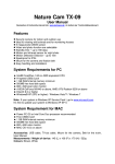
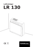
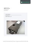
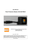
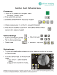
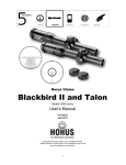
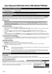
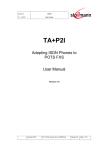
COMPACT eco -DIN Document Rev1 Datasheet Control unit for an Electric Height-Adjustable Desk LOGIC office Contents 1 2 3 4 5 6 7 8 Features ................................................................................................................................................ 3 Type and dimensions ............................................................................................................................ 4 Technical Data ...................................................................................................................................... 5 3.1 Pin assignment ............................................................................................................................. 6 3.1.1 Motor socket ............................................................................................................................ 7 3.1.2 Handswitch socket ................................................................................................................... 7 3.1.3 LogicConnector DATA ............................................................................................................. 8 3.2 Intelligent System Protection (ISP) – Anti Pinch .......................................................................... 9 3.3 Type plate..................................................................................................................................... 9 Accessories ......................................................................................................................................... 10 Order code .......................................................................................................................................... 10 End of life disposal .............................................................................................................................. 10 Standards ............................................................................................................................................ 11 Manufacturer ....................................................................................................................................... 11 A&E Trading b.v. | Lorentzpark 13 | 9351 VJ Leek | 0594 - 58 11 58 | www.aetrading.nl | [email protected] | 2 1 Features High efficient switch mode power supply (SMPS) Low standby power consumption, low field emission Control units with US and EU input voltage available Table height display with configurable offset Up to 6 memory positions (depending on handset) Up to 2 motor groups ISP (Intelligent System Protection) Enhanced Drive Comfort Safety area Low speed area Plug detection and automatic detection of the number of connected drives (depending on u Configurable reset conditions Configurable stop conditions (overtemperature, overcurrent, timeout, limit switches) InBox Diagnosis LogicConnector DATA for sensors and cascading Additional functions are available, depending on the handswitch model (e.g. saving desktop positions, adjusting the desktop to saved positions, etc.) A wide selection of LOGICDATA handswitches is available for the control units Caution: do not open the COMPACT danger of electric shock. eco used -DIN control unit under any circumstances. There is a Caution: only use the power cord supplied with the control unit. Check that it is not damaged. eco Do not ever operate the COMPACT -DIN control unit if the power cord is damaged. eco Caution: the COMPACT -DIN control unit may only be operated with mains voltage as specified on the type plate. eco COMPACT -DIN control units are also available for the mains voltages used in other countries. Detailed information is provided in the datasheet! Danger: The control unit must be mounted before commissioning and operation. eco Caution: When installing the COMPACT -DIN and putting it into operation, be sure that the eco COMPACT -DIN is acclimatized to the temperature and humidity values for operation, shown in the datasheet! Caution: do not open the COMPACT danger of electric shock. eco -DIN control unit under any circumstances. There is a Danger: in the event of a fault, please contact customer service immediately. Only original spare parts may be used for repairing the control units. Parts may only be replaced by qualified service technicians, otherwise the warranty/guarantee shall be null and void. Danger: do not expose the COMPACT eco -DIN control unit to moisture, drips or splashes. A&E Trading b.v. | Lorentzpark 13 | 9351 VJ Leek | 0594 - 58 11 58 | www.aetrading.nl | [email protected] | 3 eco Caution: only clean the COMPACT -DIN control unit with a dry or slightly moist cloth. Before cleaning, you must always unplug the power cord. Caution: unplug the power cord during a thunderstorm or if you do not intend to use the desk for a longer period. The control unit might otherwise be damaged by power surges. Danger: if strange smells or fume occur, unplug the power cord immediately. Contact LOGICDATA. eco Note: information about usage of the COMPACT -DIN can be found in the user manual eco which is valid for the firmware version of the COMPACT -DIN. Note: If there are some control units without DIN-sockets for pin assignments figured in the manual, the manual still remains valid. The information about the pin assignment of the DINsockets can be taken from this Datasheet. 2 Type and dimensions 13 37 6,8 5 2,8 103 42 45 252 264 Figure 1: Dimensions in mm; Tolerances according to DIN ISO 2768-1 c A drill template can be found in the Mounting Instructions, available as separate document. A&E Trading b.v. | Lorentzpark 13 | 9351 VJ Leek | 0594 - 58 11 58 | www.aetrading.nl | [email protected] | 4 3 Technical Data General Supply voltage EU: 207-254,4V / 50Hz US: 90-127V / 50-60Hz Nominal voltage EU: 230V / 50Hz US: 120V / 60Hz Standby power, primary (typical) 0,5 W Operating voltage for internal and external electronics 5VDC 10% 250mA and Hall sensors Operating voltage for internal and external electronics 5VDC 10% 30mA and Hall sensors in standby mode (average) Precision of Motor current measurement @ 100% Output Voltage and 4-8A per Motor ±15% Ambient temperature 0-30°C Relative humidity (for operation) 5-85% (non condensing) Storage and transport temperature -40-85°C Relative humidity (for storage) 5-90% (non condensing) Protection class (with earth terminal) I IP class IP 20 Dimensions (L x B x H) [mm] 264 x 103 x 37 Tolerances according to DIN ISO 2768-1 c COMPACT-e-3-DIN Switching cycles Depicted currents are sums over all motor channels Max. current per motor channel Weight (typical) Hi Power cycle: 20s UP: 19A@20V 20s DOWN: 7A@33V Pause: 9min 380W 231W Normal cycle 1/9: 30s UP: 15A@24V 30s DOWN: 7A@33V Pause: 9min 360W 231W Normal cycle 2/18: 2min move: 7A@33V 231W Pause: 18min 8A Maximum sum current restricted according to values shown above 523g A&E Trading b.v. | Lorentzpark 13 | 9351 VJ Leek | 0594 - 58 11 58 | www.aetrading.nl | [email protected] | 5 3.1 Pin assignment D 3 2 1 P F S Figure 2: Sockets S P F D Motor socket 1 (M1) Motor socket 2 (M2) Motor socket 3 (M3) Handswitch socket (HS) Mains socket Functional earth, cable lug for earthing the desk frame (6,3x0,8mm lug) LogicConnector DATA for sensors, squeeze lines and cascading Danger: it is not allowed to connect self-constructed products to LOGICDATA motor controls. To prevent damage of the unit, use only components suitable for LOGICDATA motor controls. A&E Trading b.v. | Lorentzpark 13 | 9351 VJ Leek | 0594 - 58 11 58 | www.aetrading.nl | [email protected] | 6 3.1.1 Motor socket 1,7 2,4 3 5 Motor + Motor +5V GND 6 8 Shell Hallsensor 2, Limit Switch 1 Hallsensor 1 Limit Switch 2 Figure 3: Pin assignment of motor socket Danger: to prevent damage of the unit, use only motors/ motor cables suitable for LOGICDATA motor controls. Pin Motor+ / Motor Hallsensor 1,2 +5V, GND Limit Switch 1,2 Description Power supply lines for motors Sensor input lines for hall sensors Power supply lines (e.g. for hall sensors) Digital sensor input lines for limit switches Danger: please observe the maximum allowable loads (currents) for the 5V circuit in normal operation and standby, shown in the technical data. The load sum attached on all interfaces of the control unit must not exceed the values for the particular operating state! 3.1.2 Handswitch socket 1 2 3 4 RxD HS3 HS1 HS4 5 6 7 Shell HS2 TxD +5V GND Figure 4: Pin assignment of handswitch socket; pin alignment according to DIN 45329 Danger: to prevent damage of the unit, use only handswitches suitable for LOGICDATA motor controls. Pin TxD / RxD +5V, GND HS X Description Pins for communication (LOGICDATA communication protocol) Power supply lines for handswitch Parallel handswitch input lines Danger: please observe the maximum allowable loads (currents) for the 5V circuit in normal operation and standby, shown in the technical data. The load sum attached on all interfaces of the control unit must not exceed the values for the particular operating state! A&E Trading b.v. | Lorentzpark 13 | 9351 VJ Leek | 0594 - 58 11 58 | www.aetrading.nl | [email protected] | 7 3.1.3 LogicConnector DATA 8 7 6 5 1 2 3 4 1 2 3 4 RxD GND Signal 3 Signal 4 5 6 7 8 Signal 2 Signal 1 +5V TxD Figure 5: Pin assignment of LogicConnector DATA Danger: to prevent damage of the unit, use only accessories suitable for LOGICDATA motor controls. Danger: be sure that the connector is plugged in correctly in the socket! Danger: when components like sensors shall be disconnected from the LogicConnector DATA, be sure to unlock the 8pin connector on the cable properly! There is a fixing hook on this connector which must be pressed. Pin TxD / RxD +5V, GND Signal 1,2 Signal 3,4 Description Pins for communication (LOGICDATA communication protocol) Power supply lines Digital I/O lines Analogue input lines Danger: please observe the maximum allowable loads (currents) for the 5V circuit in normal operation and standby, shown in the technical data. The load sum attached on all interfaces of the control unit must not exceed the values for the particular operating state! A&E Trading b.v. | Lorentzpark 13 | 9351 VJ Leek | 0594 - 58 11 58 | www.aetrading.nl | [email protected] | 8 3.2 Intelligent System Protection (ISP) – Anti Pinch Pay attention to the following instructions if you are using the new anti-pinch feature ISP ( = Intelligent System Protection). Note: please note the following for maximizing ISP functionality: To ensure the best possible pinch protection, a mechanical brake must be fitted that is applied when the electric height-adjustable desk moves down. Note: without a mechanical brake, cut-out sensitivity may be reduced under load. However, if there is no load on the desktop, ISP will function properly even without a brake. Note: the ISP-sensitivity and the ISP-cutoff value depend on the whole system (mechanical and electrical components). To evaluate the ISP-capability of a height adjustable table, please contact LOGICDATA! Danger: in spite of ISP being in place, there may still be a risk of pinching in exceptional cases, as it is not only the control unit, but also the interaction between the mechanical and electronic systems that is responsible for cutting out the motor. In addition, the mechanical components, motor and ambient conditions all affect cut-out sensitivity. As the control unit manufacturer, LOGICDATA cannot therefore eliminate this residual risk completely or accept any liability. 3.3 Type plate The following figure shows the type label and its location on the control box housing. Figure 6: Type plate (example) and its position on the COMPACTeco-DIN Note: specifications on the type label are dependent on the version of the COMPACT control box (see technical data). eco -DIN A&E Trading b.v. | Lorentzpark 13 | 9351 VJ Leek | 0594 - 58 11 58 | www.aetrading.nl | [email protected] | 9 Text alignment on the type plate Figure 7: Text alignment on the type plate of COMPACTeco-DIN 4 Accessories LOGICDATA offers a wide range of optional accessories. Please contact LOGICDATA to get a catalogue with all LOGICDATA products. 5 Order code COMPACT-e-3-n-DIN-x-y-z Number of used motors (optional, depending on parameters) Motor type (optional) Customer code (optional) Input voltage = „US“ or „EU“ Figure 8: Order code 6 End of life disposal When you no longer require the COMPACT eco -DIN control unit, please note the following for disposal: eco Note: The COMPACT -DIN control unit is electrical or electronic equipment according to directive 2002/96/EC and therefore marked with the symbol depicted on the left. Note: ensure eco-friendly disposal of all the control unit components (separate the plastic and electronic parts for collection). Also ensure eco-friendly disposal of all the other components (drives, cables, etc.). A&E Trading b.v. | Lorentzpark 13 | 9351 VJ Leek | 0594 - 58 11 58 | www.aetrading.nl | [email protected] | 10 7 Standards Europe EN 60335-1:2002+A1:2004+A11:2004+A12:2006+A2:2006+A13:2008+A14:2010 EN 61000-6-3:2007 EN 61000-6-2:2005 EN 61000-3-2:2006+A1:2009+A2:2009 EN 61000-3-3:2008 EN 62233:2008 LVD (Low Voltage Directive); EU Directive 2006/95/EC EMC (Electromagnetic Compatibility) according to EU Directive 2004/108/EC Note: this product is RoHS compliant according to directive 2002/95/EC! Note: this product is REACH compliant according to directive 2006/121/EC (Edict 1907/2006) USA and Canada UL 60950-1, 2nd Edition, 2007-03-27 (Information Technology Equipment - Safety - Part 1: General Requirements) CSA C22.2 No. 60950-1-07, 2nd Edition, 2007-03 (Information Technology Equipment - Safety - Part 1: General Requirements) Australia IEC 60335-1:2001 (Fourth Edition) incl. Corrigendum 1:2002 + A1:2004 + A2:2006 incl. Corrigendum1:2006 8 Manufacturer LOGICDATA Electronic & Software Entwicklungs GmbH A&E Trading b.v. | Lorentzpark 13 | 9351 VJ Leek | 0594 - 58 11 58 | www.aetrading.nl | [email protected] | 11