1
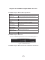
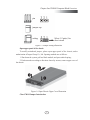
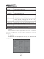
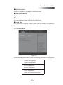
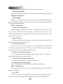
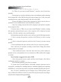
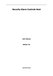
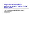
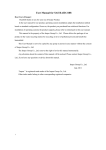
Dear users of Inspur server:
Sincerely than you for selection of Inspur server!
This manual introduces the technical characteristics and the system
installation and setup of the server, and helps you to particularly understand
and expediently use this server.
Please deliver the package of our product to the waste recycling station
for recycling, in favor of pollution prevent and benefit the humankind.
This manual is the property of the Inspur Group Co., Ltd.
This User Manual is not to be copied by any group or person in any
manner without the consent of Inspur Group Co., Ltd. The Inspur Group
Co., Ltd. reserves the right of revise this manual momentarily.
Any alteration about the content of this manual will be noticed.
Please contact Inspur Group Co., Ltd., if you have any questions or
advice about this manual.
Inspur Group Co., Ltd.
1st 2013
“Inspur” is registered trademark of Inspur Group Co., Ltd.
Other trademarks belong to other corresponding registered companies.
Statement
Please read the following statement before you use this server formally. Only
when you have read this statement hereinafter and agreed the following terms, you can
formally use this server. If you have any questions about the following terms, please
contact our supplier or us directly. If you have no questions about these terms and start
to use this server, it acquiesces that you have agreed the following terms.
1. We must call your attention that you must not alter any other parameters in
the main board BIOS of this server at any time, except for the parameters which we
promote that you can alter.
2. If there are any hardware problems when you use this server, or you wish
to upgrade the hardware, please feed back the detail hardware configuration of your
computer to our Customer Service. Don’t disassemble the server case or any hardware
components in the case by yourself.
3. In this server, the MEMORY, CPU, CPU Fan and Fan are in given standard.
Please don’t use them with the corresponding components of any other computers
confusedly.
4. When you have any software problems during the application of this server,
we hope that you firstly contact the corresponding software supplier and then he will
contact us in favor of communication so as to solve your problem together, especially
the software problems about the database, the installation and running of the network
management software or other networking product.
5. Please firstly read the accompany Brief User Guide, when you install this
server. Please contact our Customer Service Center, if you have any questions about the
application.
6. We must call your attention that in the application process, you should pay
attention to do necessary backup of your file.
7. The copyrights of the markers and names of the software and hardware product
referred in this manual are the property of corresponding companies.
8. In the above statement, “us” indicates the Inspur Group Co., Ltd. The Inspur
Group Co., Ltd. holds the right of final explanation about the above statement.
Safety Information
In order to guarantee your personal safety, avoid any risk of damaging system and
usage environment, please make sure to read this part carefully, and execute according
to this strictly, before installing and using this product.
Note: In order to help you use the equipment, the following considerations
can help avoid the occurrence of problems that may damage the components or
cause data loss etc.
1. In case of the following cases, please unplug the power line plug of products
from the power socket and contact customer service department of Inspur:
— The power cables, extended cables or power plugs are damaged.
— The products get wet by water.
— The products have fallen off or been damaged.
— Objects fall into the products.
— When operating according to the operation instructions, the products cannot
function normally.
2. If the system becomes damp, please dispose according to the following steps:
— Switch off the power supplies of the system and the equipment, disconnect
them with the power socket, wait for 10 to 20 minutes, and then open the cover of the
host.
— Move the equipment to the ventilation place to dry the system at least for 24
hours and make sure that the system is fully dried.
— Close the cover of the host, re-connect the system to the power socket, and
then start the equipment.
— In case of operation failure or abnormal situation, please contact Inspur and get
technical support.
3. Pay attention to the position of the system cables and power cables, wire them
in places not to be stepped on or knocked down and ensure not to place other objectives
on the cables.
4. Before dismounting the cover of host or contacting the internal components,
you shall cool down the equipment first; to avoid damaging the main-board, please
power off the system and wait for 5 seconds, and then dismount the components from
the main-board or disconnect the connection of peripheral equipment of the system.
5. If there are modulator-demodulator, telecommunication or local area network
options in the equipment, please pay attention to the following matters:
— In case of thunder and lightning weather, please do not connect or use the
modulator-demodulator. Otherwise, it may be subject to lightning strike.
— Never connect or use modulator-demodulator in moist environment.
— Never insert the modulator-demodulator or telephone cables to the socket of
network interface controller (NIC).
— Before unpacking the product package, contacting or installing internal
components or contacting un-insulated cables or jacks of the modulator-demodulator,
please disconnect the modulator-demodulator cables.
6. In order to prevent the electrostatic discharge from damaging the electronic
components in the equipment, please pay attention to the following matters:
— You shall conduct off the static electricity on the body before dismounting or
contacting any electronic component in the equipment. You can conduct off the static
electricity on the body by contacting the metal earthing objects (such as the unpainted
metal surface on the chassis) to prevent the static electricity on the body from
conducting itself to the sensitive components.
— For electrostatic sensitive components not ready to be installed for application,
please do not take them out from the antistatic package materials.
— During the work, please touch the earthing conductor or the unpainted metal
surface on the cabinet regularly to conduct off the static electricity on the body that
may damage the internal components.
7. When dismounting the internal components with the approval of Inspur, please
pay attention to the following matters:
— Switch off the system power supply and disconnect the cables, including
disconnecting any connection of the system. When disconnecting the cables, please
grab the connector of cables and plug it out, and never pull the cables.
— Before dismounting the cover of cabinet or touching the internal components,
the products need to be cooled down.
— Before dismounting and touching any electronic component in the equipment,
you shall conduct off the static electricity on the body by touching the metal earthing
objectives.
— During the dismounting process, the operation shall not be too big, so as to
prevent damage to the components or scratching of the arms.
— Carefully deal with the components and plug-in cards, and please never touch,
the components or connection points on the plug-in cards. When taking the plug-in
cards or components, you should grab the edges of the plug-in cards or components or
their metal fixed supports.
8. During the process of cabinet installation and application, please pay attention
to the following matters:
— After the installation of cabinet is finished, please ensure that the supporting
feet have been fixed to the rack and supported to the ground, and all weight of the rack
have been fell onto the ground.
— It shall install into the cabinet according to the sequences from the bottom to
the top, and first install the heaviest component.
— When pulling out the components from the cabinet, it shall apply force slightly
to ensure the cabinet to keep balance and stabilization.
— When pressing down the release latch of the sliding rail of components and
sliding in or out, please be careful, as the sliding rail may hurt your figures.
— Never make the AC power branch circuit in the cabinet overload. The sum of
cabinet load shall not exceed 80% of the ratings of branch circuits.
— Ensure that components in the cabinet have good ventilation.
— When repairing components in the cabinet, never step on any other
components.
Warning: the following warnings show that there are potential dangers that
may cause property loss, personal injury or death:
Warning 1: The power supply equipment in the system may generate high voltage
and dangerous electrical energy and thus cause personal injury. Please do not dismount
the cover of the host or to dismount and replace any component in the system by
yourself, unless otherwise informed by Inspur; only maintenance technicians trained
by Inspur have the right to disassemble the cover of the host, dismount and replace the
internal components.
Warning 2: Please connect the equipment to appropriate power supply, and
the power should be supplied by external power supply which is indicated on the
rated input label. To prevent your equipment from damages caused by momentary
spike or plunge of the voltage, please use relevant voltage stabilizing equipment or
uninterruptible power supply equipment.
Warning 3: If extended cables are needed, please use the three-core cables
matched with correct earthed plug, and check the ratings of the extended cables to
make sure that the sum of rated current of all products inserted into the extended cables
do not exceed 80% of the limits of the rated currents of the extended cables.
Warning 4: Please be sure to use the supplied power supply component, such
as power lines, power socket (if supplied with the equipment) etc. For the safety of
equipment and the user, do not replace randomly power cables or plugs.
Warning 5: To prevent electric shock dangers caused by leakage in the system,
please make sure that the power cables of the system and peripheral equipment are
correctly connected to the earthed power socket. Please connect the three-core power
line plug to the three-core AC power socket that is well earthed and easy to access, be
sure to use the earthing pin of power lines and do not use the patch plug or the earthing
pin unplugged with cables. In case of the earthing conductors not installed and it is
uncertain whether there are appropriate earthing protections, please do not operate or
use the equipment. Contact and consult with the electrician.
Warning 6: To avoid short circuit of internal components and fire or electric shock
hazards, please do not fill any object into the open pores of the system.
Warning 7: Please place the system far away from the cooling plate and at the
place with heat sources, and be sure not to block the air vents.
Warning 8: Be sure not to scatter food or liquid in the system or on other
components, and do not use the product in humid and dusty environment.
Warning 9: The replacement of batteries with those of another model may
cause explosion. When replacement of batteries is required, please consult first the
manufacturer and choose batteries of the same or a similar model recommended by the
manufacturer. Do not dismount, extrude and pink the batteries or make the external
connection point short circuit, and do not expose them in the environment over 60°C.
Never throw them into fire or water. Please do not try to open or repair the batteries,
and be sure to reasonably deal with the flat batteries and do not put the fl at batteries,
the circuit boards that may include the batteries and other components with other
wastes. For relevant battery recovery, please contact the local waste recovery and
treatment mechanism.
If what you bought is the chassis, besides carefully read the installation
description attached with the cabinet products and get known about the special warning
notices and installation process, you must abide by the following preventive measures
to guarantee the cabinet to be stable and safe:
Warning 10: Before installing equipment in the chassis, please install front
and side supporting feet on the independent chassis; for cabinet connecting with
other chassis, it shall install the front supporting foot first. If you fail to install
correspondingly the supporting foot before installing equipment in the chassis, it may
cause the cabinet to turn over in some cases, and thus may cause personal injury.
Therefore, it is necessary to install supporting feet before installing equipment in the
chassis. After installing the equipment and other components in the chassis, it can only
pull out one component from the cabinet through its sliding component at one time.
Pulling out several components at the same time may lead the cabinet to turn over and
cause serious personal injury.
Warning 11: Please do not move the chassis independently. Considering the height
and weight of the chassis, at least two people are needed to complete its movement.
Warning 12: Declaration
The product is Grade A product, and in the living environment, it may cause
radio interference. In such case, it may need the user to take feasible measures for the
interference.
Regarding the Manual
● Product Description
● System BIOS
● Operating System Installation
● Integrated Raid Systems
● Common Problem and Trouble-shooting
We suggest you read this manual seriously before you use this server for fear the
unnecessary faults in your operation.
Technical Service Tel.: 86-531-88546554
Address: NO.1036 Langchao Road, Jinan, China, Inspur Group Co., Ltd
Post Code: 250101
Content
Chapter One NX8840 Computer Blade Overview ..................................................1
1.1 NX8840 Computer Blade Technical Specification .......................................1
1.2 NX8840 Computer Blade View ....................................................................1
1.3 NX8840 Computer Blade Unit Interface and Indicator Introduction ...........1
1.4 Usage of NX8840 Computer Blade ..............................................................2
1.5 Jumper Setting ...............................................................................................2
Chapter Two System BIOS .......................................................................................5
2.1 How to Enter the BIOS Setup .......................................................................5
2.2 BIOS System Menu Introduction ..................................................................5
Chapter Three Operation System Installation ........................................................18
3.1 Manual Installation of Windows Server 2008 R2 .........................................18
3.2 Manual Installation of Red Hat Enterprise Linux 6.2 ...................................23
Chapter Four Integrated RAID System...................................................................28
4.1 How to Enter SATA RAID Configuration Interface......................................28
4.2 Application of Control Keys .........................................................................28
4.3 SATA RAID Configuration ...........................................................................28
Chapter Five Common Problems and Troubleshooting .........................................32
5.1 Restart the machine .......................................................................................32
5.2 Failure occurs when starting the machine .....................................................32
5.3 Other notices .................................................................................................35
5.4 Technical support information.......................................................................36
Chapter One NX8840 Computer Blade Overview
1.1 NX8840 Computer Blade Technical Specification
Processor
Processor Type
2~4 Intel® XeonSandy Bridge-EP 4600 series processors
Platform
Platform Type
Romley-EP 4S Platform(Socket-R)
Memory
Memory Type
DDR3-1600/1333/1066/800 ECC Registered
Memory Slot Qty.
32 (8DIMM/CPU)
Memory Volume
Supports maximum 512GB
Display Controller
Controller Type
Mainboard integrated display card
Hard Disk Controller
SATA Controller
Supports 2 25-inch hot plug SATA, SSD and SAS hard disks.
1.2 NX8840 Computer Blade View
Front view of NX8840 computer blade is as shown in the following Figure 1-1:
Figure 1-1 NX8840 Front View
1.3 NX8840 Computer Blade Unit Interface and Indicator Introduction
1
Chapter One NX8840 Computer Blade Overview
Figure 1-2 Blade Unit Interface and Indicator
Number
Name
Status/Function
A
Blade KVM Status Indicator/ Lights on when blade KVM is activated, blue/manual
KVM Button
activates current blade module KVM
B
Start Button/Power Indicator
C
Restart Button/Failure Indicator Lights on when blade module restarts/blade fails, red
D
USB Interface
Lights on when switch blade module/blade operates
normally and flashes when starts BMC, green
Connects USB devices
1.4 Usage of NX8840 Computer Blade
NX8840 computer blade shall use with Inspur I800 server, and computer blade
could only be used when installed in I8000 server system, about how to install NX8840
blade onto an I8000 server, please refer to related parts in I8000 server use manual or
illustration on chassis of I8000 blade server host, which is not repeated here.
1.5 Jumper Setting
Mainboard jumper setting is an operation to short circuit two pins of the jumper to
change interface functions, according to the following figure, so as to adjust mainboard
functions.
2
Chapter One NX8840 Computer Blade Overview
pin
jumper cap
setting
Select 1-2 pin(s) for
short circuit
Figure 1-3 Jumper Setting Illustration
Open upper panel of the chassis
To modify mainboard jumper, please open upper panel of the chassis, under
authorization of Inspur Group Co., Ltd. Opening methods are as follows:
1. Shut down the system, pull out blade module, and press unlock spring;
2. Push outwards according to directions shown by arrows, remove upper cover of
the chassis.
Figure 1-4 Open Chassis Upper Cover Illustration
Clear CMOS Jumper Introduction
3
Chapter One NX8840 Computer Blade Overview
Figure 1-5 Jumper Position Illustration
Jumper No.
Function Description
Jumper Functions
J38
CMOS clear jumper
Short circuit of Pin1-2, normal status;
short circuit Pin2-3, clear CMOS.
Note:
It is required to maintain 5 seconds when short circuit Pin2-3 during clearing
CMOS; then short circuit Pin1 and Pin2 of CLR_CMOS jumper again using jumper
cap (default setting status), to restore to original status.
4
Chapter Two System BIOS
Chapter Two System BIOS
2.1 How to Enter the BIOS Setup
Power on the server, system starts to boot, when the following content appears at
the bottom of the screen:
“Press <DEL> to SETUP or <TAB> to POST”, press [DEL] key, wait to enter
system BIOS Setup.
If system fails to enter configuration program according to the above operation,
please press [Ctrl]-[Alt]-[Del] to restart system, repeat the above operation (if [DEL]
key is pressed after seeing the above content, complete the press action immediately).
Note: Some items in BIOS are unable to be configured, i.e. some system autodetection and configuration information. There’s a right indicator in front of some
items, indicating that if this item is selected,, press [Enter] key, cascade menu of it (which
is sub-menu) will display on the screen.
2.2 BIOS System Menu Introduction
This chapter mainly introduces the following main function menus, as well as
notes in BIOS.
Function Menu:
Menu Name
Menu Function
Main
To configure basic system settings, i.e. system time, system date,
BIOS, Memory information display etc.
Advanced
To configure advanced features of CPU, integrated SATA controller
and SAS controller etc.
Chipset
To configure memory mode, and CPU property etc.
Server Mgmt
To display network configure parameters of BMC.
Boot
To configure boot sequence of all devices of the system.
Security
To configure system administrator and user passwords.
Save & Exit
To save BIOS Setup, and to exit BIOS Setup etc.
5
Chapter Two System BIOS
Operation key instructions:
Press Key
Description
↑ (Up Key)
To select the previous menu or value.
↓(Down Key)
To select the next menu or value.
← (Left Key)
To select the left menu or value.
→ (Right Key)
To select the right menu or value.
Esc Key
To exit or return to the previous menu or return to the main menu.
+ Key
To change option value. To change the current option value in menu to
the previous option value. This key only displays values related to the
selected option, rather than values of all options.
- Key
To change option value. To change the current option value in menu
to the next option value. This key only displays values related to the
selected option, rather than values of all options.
F1 Function Key
Help hotkey, able to display related instructions on the current menu.
F2 Function Key
To restore to previous default settings.
F9 Function Key
To restore to default settings for system optimal performance.
F10 Function Key
To save settings and to exit.
Enter Function Key
To execute current command or enter sub-menu.
Declaration:
We only explain some common options in BIOS, and it is not required to set
during usage, or suggested that users shall set options by themselves, which is not
repeated here.
2.2.1 Main Menu
Enter BIOS setup, main menu displays first, user could view BIOS version and
memory volume in this menu, and could set system time and date etc.
Figure 2-1
6
Chapter Two System BIOS
● BIOS Information
Displays system BIOS version, BIOS modification time.
● Memory Information
Displays system memory volume.
● System Date
Sets system date, the format is [Week Day/Month/Year]
● System Time
Sets system time, adopting 24-hour system, and the format is [Hour/Minute/
Second].
2.2.2 Advanced Menu
Figure 2-2
Advanced menu options mainly contain the following sub-menus or setup options:
Launch PXE OpROM
WHEA Configuration
CPU Configuration
SATA Configuration
SAS Configuration
Serial Port Console Redirection
7
Chapter Two System BIOS
Main and common options will be introduced in the following.
◇ Launch PXE OpROM
There’re two options of [Disabled] and [Enabled], which are both open by default.
● WHEA Configuration
◇ WHEA Support
WHEA is a universal function of basic structure provided for handling hardware
errors on Windows platform, and there’re two options of [Disabled] and [Enabled],
which are both open by default.
● CPU Configuration
◇ Socket 0/1 CPU Information
Displays detailed information of CPU0/1, including information such as basic
frequency size of CPU, max. basic frequency, min. basic frequency, CPU cores,
whether supporting hyper-threading and VT-X technology, level 1 cache, level 2 cache
and level 3 cache sizes etc.
◇ Hyper-threading
CPU hyper-threading function setting, there’re two options of [Disabled] and
[Enabled], which are both open by default.
◇ Active Processor Cores
Activates all CPU cores, there’re [All], [1], [2], [4] and [6] options (which will
be different according to configured CPU cores, i.e. when 4 CPU cores are configured,
options are [All], [1] and [2]), and the default is [All].
◇ Intel(R) Virtualization Technology
CPU virtualization technology support function setting, there’re two options of
[Disabled] and [Enabled].It is open by default.
◇ CPU Power Management Configuration
Enter this option to manage CPU energy consumption.
◇ Configuration Power Technology
There’re three options of [Disabled],[Energy Efficient] and [Custom].
● SATA Configuration
After entering this option, situation of SATA equipment connected to all SATA
interfaces will display.
◇ SATA Mode
This option is used to set mainboard integrated SATA controller mode, and
there’re four options of [Disabled], [IDE Mode], [AHCI Mode] and [RAID Mode].
8
Chapter Two System BIOS
◇ Serial-ATA Controller 0
This option only appears when SATA Mode option is set to [IDE Mode], which
could be set to [Disabled], [Enhanced] and [Compatible].
● SAS Configuration
After entering this option, situation of SATA equipment connected to all SATA
interfaces will display.
When [Chipset]->[South Bridge]->[Scu devices] is set to [Disable], this option
will not display.
● Serial Port Console Redirection
Enter this option to configure serial port reorientation function.
2.2.3 Chipset Menu
Figure 2-3
Chipset menu mainly contains the following submenus:
North Bridge
South Bridge
ME Subsystem
Major and common options are introduced in the following.
9
Chapter Two System BIOS
2.2.3.1 North Bridge
Figure 2-4
IOH
Confi
guration
●
This menu is mainly used to set open and close of VT-d as well as speed of PCIE port.
Figure 2-5
◇ Intel(R) VT for Direct I/O Configuration
Whether Directed I/0 supports Intel virtualization technology. There’re two
options of [Disabled] and [Enabled], which are closed by default.
◇ Link Speed
To set the speed of PCIE port, and there’re three options of [Gen1], [Gen2] and [Gen3].
Note: If Gen3 is selected as the speed of port, it is required to open [Gen3
10
Chapter Two System BIOS
Equalization WA’s] synchronously.
● QPI Configuration
Sub-menu options of this menu could be used to set QPI speed mode and
frequency etc.
● Memory Mode
As for memory mode configuration, there’re four options of
[Independent],[Mirroring], [Lock Step] and [Sparing], and the default is [Independent].
To enable [Mirroring] function, it is required to configure the same memory for
DIMM 0/1 and 2/3 under each CPU, when enabled, CPU0, 2 will be used as mirror
masters, and 1, 3 will be used as mirror slaves of 0, 2, while system writing memory,
content written into masters will also be written into slaves meanwhile. At this time,
memory seen under the system is half of actual memory.
To enable [Lock Step] function, it is required to configure the same memory
for DIMM 0/1 and 2/3 under each CPU, and memory correction capacity could be
promoted via enabling the function.
To enable [Sparing] function, it is required to configure memory above 2
rank individually, when enabled, system selects a certain rank to abandon, when
accumulated errors of other ranks on this memory reach a certain threshold, error ranks
will be mapped out, and replaced by ranks previously selected, after that, this DIMM
will have no sparing function. When set to [sparing] mode, memory seen under the
system will be less than actual memory.
Note: To set to [Sparing] or [Mirroring] mode, it is required to configure memory
complying with related conditions, at this time, Sparing or Mirroring information on
this option will display as ‘support’, otherwise, the setting will be invalid.
● Patrol Scrub
When this function is enabled, CPU will read and verify all memories installed on
the system within a certain period of time (24 hours), and will correct initiatively if any
ECC error is found.
● Demand Scrub
When this function is enabled, CPU will correct any Ecc error found, during CPU
reading certain segment of memory.
● Device Tagging
When this function is enabled, if certain particle in single rank inside DIMM
errors, it will be replaced by particle used for correction, after that, this rank will have
11
Chapter Two System BIOS
no device tagging function, with correction capacity reduced.
● Data Scrambling
When this function is enabled, it could avoid signal error caused by continuous ‘0’
or ‘1’ occurred in single bit.
● Thermal Throttling
There’re three options [Disable][CLTT][OLTT].
Thermal Throttling is an over temperature protection function.
There’re two types:
CLTT->Memory temperature is read via built-in memory sensor (TSOD), when
temperature reaches a certain threshold, it will reduce bandwidth automatically.
OLTT->for memory without built-in sensor (TSOD), limits bandwidth at the value
set by [OLTT Peak BW %].
● Altitude
A Thermal Throttling calculated parameter, which is the altitude of the machine.
● Rank Margin
When enabled, it is used for memory testing, at this time, system operates slowly,
which impacts performance seriously. It is disabled by default.
● Serial Message Debug Level
Rank Margin tests related settings.
● DIMM Information
Options of this menu could display memory configuration information, including
memory volume, and current memory configuration module.
2.2.3.2 South Bridge
This menu mainly displays related PCH information, such as display and setting.
Figure 2-6
12
Chapter Two System BIOS
● Restore AC Power Loss
Power status setting after system powered off.[Power 0ff] indicates a shutdown
status, which needs to start up manually; [Last State] indicates a power-off status; [Power
On] indicates an automatic startup status.
● SCU device
This option is used to enable or disable SAS controller, and there’re two options
of [Enabled] and [Disabled].
To connect SAS hard disk, it is required to set this option to [Enabled].
● Onboard SATA RAID Oprom
This option is used to enable or disable integrated SAS RAID controller rom, and
there’re two options of [Enabled] and [Disabled].
When SATA mode is set to ‘raid mode’, it is required to set this option to [Enabled].
● USB Configuration
Controls USB enable/disable.
2.2.3.3 ME Subsystem
This menu is used to display related information about ME subsystem. It contains
information such as BIOS interface version information, version, FW status and FW
error codes etc.
2.2.4 Server Mgmt Menu
Figure 2-7
13
Chapter Two System BIOS
● BMC Support
There’re two options of [Enable] and [Disable], controlling interaction
information between BIOS and BMC.
● BMC network configuration
This menu is used to display information configuration on BMC network
interface.
2.2.5 Boot Menu
Boot menu is mainly used to set priority of system guiding equipment.
Figure 2-8
● Quiet Boot
There’re two options of [Disabled] and [Enabled]. When [Disabled] is selected,
normal self-checking information will display during system startup. When [Enabled]
is selected, OEM LOGO rather than self-checking information will display during
system startup.
● Boot Option #1/#2#3
Enter this menu, select equipment option of a certain guiding sequence, press
enter to pop up selectable guiding equipment table, select certain equipment via arrow
button and then press enter to complete setting this guiding sequence option.
● Hard Drive BBS Priority
Press [Enter] to enter sub-option of this menu, user could set guiding sequence of
the equipment.
14
Chapter Two System BIOS
2.2.6 Security Menu
Figure 2-9
● Administrator Password
This option is used to set system administrator password. When administrator
password is set, it is required to input password on user level or above when entering
BIOS setup.
● User Password
This menu is used to set user password. When user password is set, during
system startup and entering BIOS Setup, it is required to enter administrator password
and user password, in BIOS Setup interface, all privileges will be inferior to those of
administrator after entering user password.
2.2.7 Save & Exit Menu
Options in this menu could be used to realize saving or canceling modification in
BIOS configuration, and to exit configuration.
15
Chapter Two System BIOS
Figure 2-10
● Save Changes and Exit
Select this option, press [Enter], and select [Yes] in prompt popped up, all
changes made in BIOS configuration will be saved, and system will exit BIOS
configuration. This menu function could be realized using shortcut key [F10].
● Discard Changes and Exit
Select this option, press [Enter], and select [Yes] in prompt popped up, all changes
made in BIOS configuration will be discarded, and system will exit BIOS configuration.
● Chapter Two Save Changes and Reset
Select this option, press [Enter], and select [Yes] in prompt popped up, all changes
made in BIOS configuration will be saved, system will exit BIOS configuration, and
then restart the computer.
● Chapter Three Discard Changes and Reset
Select this option, press [Enter], and select [Yes] in prompt popped up, all changes
made in BIOS configuration will be skipped, system will exit BIOS configuration, and
then restart the computer.
● Saving Changes
Select this option, press [Enter], and select [Yes] in prompt popped up, all changes
made in BIOS configuration will be saved, and system will not exit BIOS configuration.
● Discard Changes
Select this option, press [Enter], and select [Yes] in prompt popped up, all
16
Chapter Two System BIOS
changes made in BIOS configuration will be discarded, and system will not exit BIOS
configuration.
● Restore Defaults
Select this option, press [Enter] and select [Yes] to confirm, default system
optimal settings will be loaded, while system will not exit BIOS configuration. This
menu function could be realized using shortcut key [F9].
● Save as User Defaults
Select this option, press [Enter], and select [Yes] to confirm, set values of all
current BIOS options will be saved as user default options.
● Restore User Defaults
Select this option, press [Enter], and select [Yes] to confirm, user default values
will be loaded.
● Boot Override
Select device option in this menu, and then press [Enter] to confirm, system will
boot from the selected device.
17
Chapter Three Operation System Installation
Chapter Three Operation System Installation
This chapter mainly introduces operation system installation of this server:
● Use an operation system disk to boot and install operation system manually
During manual installation of operation system, some operation systems
may need to use floppy drive or Inspur U drive disk to load driver of hard drive
controller, as for methods to make floppy drive of driver, users could refer to
readme.pdf file under root directory of Inspur system CD driver, for methods to
make Inspur U drive disk and drive load notices, please refer to Inspur U Drive
Disk Manual Instruction.
In drive make interface logging to driver program, user could view and make
controller driver program to be loaded during operation system installation under
related configuration. Description about operation system installation is based on
a 64-bit system.
As for whether version of operation system you’ve selected is supported by
configuration of purchased machine, it is suggested that you should confirm in advance.
3.1 Manual Installation of Windows Server 2008 R2
3.1.1 Preparation before Installation
● Windows Server 2008 installation CD (DVD)
● Inspur drive CD
● Hard disk controller drive floppy disk
● For the above drives, is a USB floppy drive is used, please make driver program
into a floppy disk; if an Inspur drive U disk is used, please make driver program into
an Inspur drive U disk; if a normal drive U disk is used during drive make, input drive
occupied by normal U disk and directory to store drive according to hints, to make the
drive to a normal U disk.
3.1.2 Installation Steps
1. Connect USB floppy drive or Inspur U drive disk or normal U drive disk,
power on server, put Windows Server 2008 installation CD into the drive, enter BIOS
for setting, so as to enable server to boot from CD.
2. If system prompts to press any key to confirm to boot installation from
18
Chapter Three Operation System Installation
CD, otherwise system will boot from CD to start Windows installation program
automatically.
3. In language setting interface, select and set languages and other primary options
according to actual needs, and then [Next] to continue.
4. Click [Install Now] in installation confirmation interface to continue.
5. Input product key (25 characters), and then click [Next] to continue.
If select “Activate Windows automatically when connected” option under the
key, 3 days after the first login, auto activation will try to activate your Windows;
after Windows installation, user will have 30 days to activate Windows online (or via
telephone), if the 30-day limit expires before the activation is completed, Windows will
stop.
6. In “Please read license terms” interface, user could understand license terms of
Microsoft, select “I accept permit terms” option after reading, and then click [Next] to
continue.
7. Select installation type, here it’s first installation by default, select “Custom
(Advanced)” to continue.
8. System enters “Where do you want to install Windows” interface, if no hard
disk controller driver program is required to be loaded, current disk partition and
unallocated space on this computer will display in main interface. No drive is required
to be added for external LSI 2108 RAID card configuration, to add a drive, please
operate according to the following steps.
If a USB floppy drive is used:
① Make a drive floppy disk, during server power-on, connect floppy drive to
USB interface of the machine, and insert floppy disk into floppy drive;
② Click [Browse] in “Load driver program” interface, select driver “floppy disk
driver (A:)” in prompt popped up, click [OK] to continue;
③ System will searches driver program automatically, click [Next] in “Select
driver program to install” interface to continue.
④ After drive loading, detected disk will be displayed, and hard disk controller
driver program is done.
If an Inspur drive U disk or a normal U disk is used:
① Make hard disk controller driver program into [3.5 floppy disk (A:)] of an
Inspur drive U disk or a normal U disk;
② When power on server to install operation system, connect an Inspur drive U
19
Chapter Three Operation System Installation
disk or a normal U disk to USB interface of server;
③ In “Where do you want to install Windows?” interface, select [Load driver
program];
④ System pops up a window, indicating to insert an installation media containing
driver program files, select [OK] directly when using an Inspur drive U disk, select path
containing the drive when using a normal U disk, then select [OK];
⑤ System will display a detected driver program list, please select the drive to
install, here we use default selection, and click [Next] to continue;
⑥ After drive loading, detected disk will be displayed, and hard disk controller
driver program is done.
9. System returns to “Where do you want to install Windows” interface, existing
disk partition and unallocated space on this computer will be displayed in main
interface, click [drive option] to carry out disk partition.
In disk partition operation interface, users could carry out the following operation:
⊙ Select existing disk partition, and then click [Delete] to delete existing
partition.
⊙ Select existing disk partition, and then click [Format] to format existing
partition.
⊙ Select unallocated disk space, and then click [New] to create a new partition.
Users could carry out operation according to actual needs. Taking disk without
created partition as an example:
① Select unallocated space of the disk, then click [New], delete numbers in
partition size box, enter partition size to be created (unit is MB), and then click [Apply]
to continue.
Note: Partition is suggested to be above 30GB.
② Select disk partition newly created, and then click [Format], click [Ok] in
conformation interface to continue.
③ After formatting partition, click [Next] to continue.
10. System starts to install Windows, and should complete operations such as
copying files, extending files, installing functions, installation updating and completing
installation etc., and system may restart several times automatically during this process.
Note: The above installation steps for Windows Server 2008 operation system
may be different for different versions of system CDs used, please operate according to
actual interfaces displayed during installation.
20
Chapter Three Operation System Installation
3.1.3 Install Driver
1. After system completes installation, “User must change password before first
login” will prompt before login into the system, click [Ok], and take out installation
CD. Set new password in password input field according to prompt on interface,
press Enter to continue, if password complies with requirements, system will prompt
“Password has been changed”, click [Ok] to login the system.
2. In “Initial Configuration Tasks” interface, select “Do not display this window
during login”, and then click [Close], in newly popped up “Server Manager” interface,
select “Do not display this console during login” and then close the interface.
3. Install chip set patch
① Input Inspur drive CD into the drive, in automatic play interface popped up
after running CD, click install or run blue dolphin icon under operation program option,
enter navigation code on CD cover of driver in navigation code interface, click [Ok] to
enter installation interface automatically;
② In “Please select operation system” field, select Windows 2008 R2;
③ In “Please select components” field, select chip set patch;
④ Click [Next] to start installation;
⑤ Enter welcome to use installation program interface, click [Next] to continue
installation;
⑥ Enter license agreement interface, select [Yes], to continue installation;
⑦ Enter Readme file information interface, click [Next] to continue installation;
⑧ Installation program starts, and displays installation schedule, after installation
completes, click [Next] to continue;
⑨ In installation complete interface, click [Done], take out Inspur drive CD, and
restart system.
4. Install net card driver
① Install Inspur driver CD into the drive, in automatic play interface popped up
after CD running, click Install or blue dolphin icon under operation program options,
please input navigation code on driver CD cover in Please Input Navigation Code
Interface, click [Ok] to enter installation interface automatically;
② In “Please select operation system” field select: Windows 2008 R2;
③ In “Please select components” field select: Net card drive;
④ Click [Next] to start installation;
⑤ Enter “Intel (R) network connection” interface, click [Install Driver and
21
Chapter Three Operation System Installation
Software] option;
⑥ Enter welcome to use interface, click [Next] to continue;
⑦ Enter “License Agreement” interface, select “I accept terms in this license
agreement”, and then click [Next] to continue;
⑧ Enter “Installation Options” interface, click [Next] to continue;
⑨ Enter “Already prepared for program installation” interface, click [Install] to
continue;
⑩ Installation program starts; after installation completes, click [Done] according
to prompt.
5. Install display card driver
After installing net card drive, do not exit installation interface of driver CD, and
continue installation of display card drive.
① In “Please select operation system” field select: Windows 2008 R2;
② In “Please select components” field select: Display card drive;
③ Click [Next] to start installing;
④ Enter “Welcome to the InstallShield Wizard” interface, click [Next] to
continue;
⑤ Enter “License Agreement” interface, select “I accept the terms in the license
agreement”, then click [Next] to continue;
⑥ Enter “Customer Information” interface, please enter User Name and
Organization, then click [Next] to continue;
⑦ Enter “Setup Type” interface, please select installation type, there’re two
options of “Complete” and “Custom”, select “Custom” here, click [Next] to continue;
⑧ Enter “Custom Setup” interface, click [Next] to continue;
⑨ Enter “Ready to Install the Program” interface, click [Install] to start installing
display card driver;
⑩ Installation program starts and completes installation, in “InstallShield Wizard
Completed” interface, please click [Finish], system pops up a window, indicating to
restart server to make configuration effective, take out all disks from the driver, and
select [Yes] to restart server.
Note: During installation of the above display card driver programs, for different
versions of Windows 2008 system installed, some installation steps may be different,
please refer to actual installation.
6. Install HCA card drive
22
Chapter Three Operation System Installation
① Insert an Inspur drive CD into CD driver, in autoplay interface popped up after
running, click install or run blue dolphin icon under program option, input navigation
code on drive CD cover in Please enter navigation code interface, click [OK] to enter
installation interface automatically;
② Select in “Please select operation system” column: Windows 2008 R2;
③ Select in “Please select component” column: HCA card drive;
④ Click [Next] to install;
⑤ Enter “Welcome to the InstallShield Wizard for MLNX_VPI” interface, and
click [Next] option;
⑥ Enter “License Agreement” interface, select “I accept the terms in the license
agreement”, then click [Next] to continue;
⑦ Enter “Destination Folder” interface, click [Next] to continue;
⑧ Enter “Maximum Performance” interface, click [Next] to continue;
⑨ Enter “Ready to Install Program” interface, click [Install] to continue;
⑩ Installation program start to install; after installation is done, click [Finish]
according to hints. Finish installation of HCA card drive.
3.2 Manual Installation of Red Hat Enterprise Linux 6.2
3.2.1 Preparation before Installation
● Red Hat Enterprise Linux 6.2 Installation CD (1 DVD)
3.2.2 Installation Steps
1. Power on system, insert installation CD into CD drive (taking DVD installation
drive for example), enter BIOS to set up, to enable server to boot from CD.
2. System enters Welcome to Red Hat Enterprise Linux 6.2 ! interface, there’re
the following options:
Install or upgrade an existing system
Install system with basic video driver
Rescue installed system
Boot from local driver
Use Up/Down arrow to select options, here it is the first installation by default,
select “Install or upgrade an existing system”, press Enter button to continue
installation.
3. System prompts Disc Found, to begin testing the media before installation press
23
Chapter Three Operation System Installation
OK.
Choose Skip to skip the media test and start the installation.
4. Enter RED HAT ENTERPRISE LINUX 6 interface, select [Next] to continue
installation.
5. System enters “What language would you like to use during the installation
process?” interface, select languages needed to be used during installation, here we
select “English(English)”, and then select [Next] to continue.
6. Enter Select the appropriate keyboard for the system interface, select keyboard
type according to actual situation, here we select “US.Englsh”, and then select [Next]
to continue.
7. Installation enters: What type of devices will your installation involve ?
Basic Storage Devices
Installs or upgrades to typical type of storage devices. If you’re not sure which
option is right for you? This is probably it.
Specialized Storage Devices
Installs or upgrades to enterprise devices such as Storage Area Networks (SANs).
This option will allow you to add Foe/Ischia/Zech disks and to filter out devices the
installer should ignore.
Here we select Basic Storage Devices, and then select [Next] to continue.
8. System enters Please name this computer. The hostname identifies the computer
on a network..
Please enter: Hostname name.
Here we could also select [Configure Network] on lower left corner of the
window, to carry out network configuration, add or delete net card, and to carry out
network IP address configuration. After network configuration is done, select [Next] to
continue.
9. Installation program enters “Please select the nearest city in your time zone:”
zone selection interface, select “Asia/shanghai”, and then click [Next] to continue.
10. Installation program enters Set Root Password interface, configure according
to your needs, while password should be at least 6 bits, and then click [Next] to
continue.
The root account is used for administering the system. Enter a password for the
root user.
11. Installation program enters “Which type of installation would you like?”
24
Chapter Three Operation System Installation
installation method selection interface, there are the following installation options:
Use All Space
Replace Existing Linux System(s)
Shrink Current System
Use Free Space
Create Custom Layout
This installation takes custom manual partition as an example, select “Create
Custom layout”, and click [Next] to continue.
12. Installation program enters installation hard drive selection interface, in Data
Storage Devices (to be mounted only) list, system displays detected storage devices.
Please click hard drive of system to be installed according to actual needs, to add
this hard drive under “Install Target Devices” list, and select one hard drive as “Boot
Loader”, and then click [Next] to continue installation.
13. Installation program enters “Please Select A Device” partition creation
interface, (if partition has been created on hard drive, existing partition will display,
which could be deleted if not required).
Double click Free partition or other existing partitions under hard disk, or click
[Create] button in lower right corner, system will pop up “Add Partition”.
① Create root partition (/) and boot partition: In Mount point select root partition:
/, in Allowable Drives window select a hard drive needing to install system, input
partition size in Size(MB), click [OK] to complete creation of root partition. Create
boot partition with the same way: /boot.
② Create Swap partition (Swap): Select “Swap” in File system Type, select a hard
drive needing to install system in Allowable Drives window, input Swap partition size
in Size(MB) (according to memory size, if memory size is under 512MB, set according
to 2 times of the memory, if memory exceeds 512MB, set Swap partition size to 2GB),
click [OK] to complete Swap partition creation.
Users could also create other partitions according to needs, after creating partition,
click [Next] to continue installation.
14. System pops up a prompt “Writing storage configuration to disk”.
The partitioning options you have selected will now be written to disk. Any data
on deleted or reformatted partitions will be lost.
Select “Write changes to disk” to continue installation, system starts to format
hard drive partition.
25
Chapter Three Operation System Installation
15. Installation program enters Boot Loader configuration interface, set according
to needs, and then click [Next] to continue installation.
16. System prompts “The default installation of Red Hat Enterprise Linux is a
basic server install. You can optionally select s different set of software now”.
Please select the type to be installed as well as software kit to be customized
according to actual needs. Select “Customize now”, click to continue installation.
17. Installation program enters program kit selection interface, please select
according to actual needs, after confirming software kit to be installed, click [Next] to
continue installation.
Here we select Desktop and X Windows System in Desktops and Development
Tools Kit in Development.
18. Installation program starts to construct file system and copy files.
19. System enters “Congratulations, your Red Hat Enterprise Linux installation
is complete.” Interface, indicating installation succeeds. Click [Reboot], take out
installation CD, system will restart automatically.
20. System enters “Welcome” interface after restart, click [Forward] to continue
installation.
21. Installation program enters “License Information” interface, select “Yes,I
agree to the License Agreement”, and click [Forward] to continue installation.
22. Installation program enters “Set Up Software Updates” interface, click
[Forward] to continue installation.
23. Installation program enters “Create User” interface, users could set user
password, add new user according to actual needs, and then click [Forward] to continue
instillation.
24. Installation program enters “Date and time” interface, please set correct time
and date, and then click [Forward] to continue installation.
25. Installation program enters Kdump configuration interface, please set
according to actual needs, and then click [Finish] to finish installation.
26. Input Username and Password to login the system.
3.2.3 Load HCA Card Drive
1. Insert Inspur drive CD into the driver, left click [Applications]→[Accessories/
System Tools]→[Terminal] on desktop
Input mount -o ro,loop MLNX_OFED_LINUX-<ver>-<OS label>.iso /mnt in
26
Chapter Three Operation System Installation
terminal window occurred:
2. Enter /mnt directory to run installation script, to complete drive installation
automatically
/mnt/mlnxofedinstall
(1) Input “mst start” in terminal window after drive installation
Starting MST (Mellanox Software Tools) driver set
Loading MST PCI module - Success
Loading MST PCI configuration module - Success
Create devices
MST modules:
-----------MST PCI module loaded
MST PCI configuration module loaded
If the above information is displayed, it indicates to load drive normally
(2) Input “mst status”
MST devices:
-----------/dev/mst/mt4099_pciconf0
- PCI configuration cycles access.
bus:dev.fn=02:00.0 addr.reg=88 data.reg=92
Chip revision is: 01
/dev/mst/mt4099_pci_cr0
- PCI direct access.
bus:dev.fn=02:00.0 bar=0xdfb00000 size=0x100000
Chip revision is: 01
If the above information is displayed, it indicates HCA device is recognized
normally and could be used
3. Driver program uninstall
Execute /mnt/uninstall.sh, system prompts “Do you want to continue? [y/n]”,
input “y” to finish driver program uninstall automatically.
27
Chapter Four Integrated RAID System
Chapter Four Integrated RAID System
This chapter mainly introduces configuration of mainboard integrated SATA
controller RAID and its usage.
To use a mainboard integrated SATA RAID, it is required to enter BIOS, set
Chipset→PCH→SCU devices option to [Enabled], and then set Onboard SATA Oprom
option to [Enabled].
4.1 How to Enter SATA RAID Configuration Interface
1. During system startup, the following content will display on the screen:
Press<CTRL-I> to enter Configuration Utility…
2. Press [Ctrl][I] to enter SATA RAID configuration interface.
4.2 Application of Control Keys
Press Key
Description
↑↓
Used to move cursor in different menus or to change values
of menu options.
TAB
To select the next menu setting option.
Enter
To select menu.
Esc
To exit menu or return to previous menu from sub-menu.
4.3 SATA RAID Configuration
After entering SATA RAID configuration interface, menu list information,
information of hard disk connecting to SATA controller (hard disk ID number, hard disk
type, hard disk capacity as well as whether hard disk is a volume member etc.), existed
RAID volume information (including volume ID number, name, RAID level, capacity,
status, whether information bootable) will all display. As shown in the following figure:
28
Chapter Four Integrated RAID System
4 executable menus in this SATA RAID configuration interface are listed in the
following:
● Create RAID Volume
To create an RAID volume.
● Delete RAID Volume
To delete an existed RAID volume.
● Reset Disks to Non-RAID
To reset hard disks in RAID volume, and to restore them to non-RAID status.
● Exit
To exit SATA HostRAID configuration interface.
I.Create RAID Volume Menu
After entering SATA RAID configuration interface, use up and down arrow
buttons to select this menu, then press [Enter] to create an RAID volume menu, or input
number in front of the menu directly to create an RAID volume menu.
System displays the following menu options:
Name:Please enter a volume label less than 16 characters not containing any
special character.
RAID Level:Please select RAID volume level, if no volume has been created
at present, there’re four volume levels of RAID0(Stripe), RAID1(Mirror),
RAID10(RAID0+1) and RAID5(Parity)for selection, please select volume level
according to actual requirements.
RAID0:This RAID volume is allowed to be made on 2 or above hard disks.
RAID1:This RAID volume is allowed to be made on 2 hard disks.
RAID10:This RAID volume is allowed to be made on 4 hard disks, which is
29
Chapter Four Integrated RAID System
only available when hard disk quantity is 4 or above.
RAID5(Parity):This RAID volume is allowed to be made on 3 or above hard
disks.
Disks:Select hard disks to make RAID volume, press enter after this option
is selected, system will enter hard disk selection interface, please select hard disks to
make RAID volume using space key in succession, and then press enter to return to
volume create menu.
Strip Size:Please select strip size, only RAID0 and RAID5 volumes could select
this option.
Capacity:Select volume capacity, which is the max. volume capacity by default.
After completing the above configuration, please select [Create Volume], and
press enter, system prompts: “WARNING:ALL DATA ON SELECTED DISKS
WILL BE LOST. Are you sure you want to create this volume ?(Y/N):”.
To create an RAID volume, please enter “Y”, a volume will be created, and all
data on the selected disks will be lost.
Otherwise, please enter “N”, to exit volume creation.
Here we enter “Y” to create an RAID volume, after creation, return to SATA
HostRAID configuration main interface, and the created RAID volume will display in
RAID volumes.
II. Delete RAID Volume Menu
After entering SATA RAID configuration interface, use up and down arrow
buttons to select this menu, then press [Enter] to delete RAID volume menu, or input
number in front of the menu directly to enter delete RAID volume menu.
System prompts: “Deleting a volume will reset the disks to non-RAID. Warning:
ALL DISKS DATA WILL BE DELETED.”。
To delete an RAID volume, please press [DEL], system prompts: “ALL DATA IN
THE VOLUME WILL BE LOST! Are you sure you want to delete ‘Volume*’?(Y/N):”,
to delete this RAID volume, please enter “Y”, to cancel deletion of this RAID volume,
please enter “N”.
III. Reset Disks to Non-RAID Menu
After entering SATA RAID configuration interface, use up and down arrow
buttons to select this menu, then press [Enter] to enter this menu, or input directly.
System will display all hard disks in RAID volume, please select hard disks to
be reset using space key according to actual requirements, and then press enter to reset
30
Chapter Four Integrated RAID System
hard disks, system prompts whether to reset hard disks, key in “Y” or “N” according to
prompt. Note: While resetting hard disk, data on this disk will all be lost, meanwhile,
this disk will not belong to RAID volume any more.
IV.Exit Menu
After entering SAS RAID configuration interface, users could use up and down
arrow buttons to select this menu, and then press [Enter] to enter this menu.
System prompts: " Are you sure you want to exit?(Y/N):”, enter “Y”, to exit
SAS RAID configuration interface, enter “N”, to cancel exit operation.
31
Chapter Five Common Problems and Troubleshooting
Chapter Five Common Problems and Troubleshooting
This chapter introduces the information concerning common problems and trouble
removal. If you are not sure the failure cause and removal method, please contact our
customer service center for solution.
Note: When replacing or installing the hardware device for the server, please
disconnect the power cable from the server completely. It is suggested to use the antistatic wrist strap when dismounting the server and earth the other end to provide
electrostatic protection.
5.1 Restart the machine
When a failure occurs, try to restart the machine according to the following
methods first.
Purpose
Operational approach
Restart the software and clear up system RAM and restart the operating
<Ctrl+Alt+Del>
system.
Clear up system RAM, self-check the POST again and restart the
Reset button
operating system.
Cold boot again, close the system power switch and start so that to clear
up the system RAM. Self-check the POST again, restart the operating Power button
system and power up all peripherals again.
5.2 Failure occurs when starting the machine
Some problems often occur when starting the machine generally due to incorrect
hardware installation and configuration. You may find and remove the problems
referring to the following methods.
5.2.1 No system power
When pressing the power switch, the power light is not on and the system is still
in non-electric state. Please solve according to the following steps:
1. Check whether your power socket can supply power normally and power cable
is connected correctly or not.
2. Press the power switch for many times to start (pay attention not to exert too
large force from your finger)
32
Chapter Five Common Problems and Troubleshooting
3. Disconnect the power cable of the system and open the case to check.
4. Check the fastness of the cable connection in the case and accessory plugging.
5. Remove other external components than Inspur ones.
6. Pack the case, connect the power cable correctly and start the machine.
5.2.2 Displ
ay doesn’t work
It can be electrified (the host can start and run normally), but the display doesn’t
work:
1. Check the correctness and fastness of the signal cable and power cable of the
display.
2. Make sure to power on the display
3. Adjust the contrast and brightness of the display and determine whether it can
display or not.
4. Shut down the system and disconnect the power cable to check whether there is
curve in the pin at the connecting end of the display signal cable and host.
5. Replace another display for test if possible.
6. If the machine is installed with other components than Inspur ones. Please
remove it first.
7. With the permission of Inspur technical support personnel, pull and plug RAM
and clear CMOS for test.
5.2.3 Installation system can’t find the hard disk
1. When install the system directly booted with the system CD, if it prompts that
no hard disk can be found, please pay attention to the normality of the disk state and
power-on self-check hard disk state.
2. If the power-on self check can detect the hard disk but the hard disk can’t
be detected when installing the system, it may be caused by the following several
conditions:
● When use Jierui management software CD to install system, if “No matched
storage controller” is prompted after entering navigation number and system installation
information, please confirm whether navigation number is input correctly.
● Because the navigation serial number is different when storage configuration
has been changed, so you should obtain the new navigation serial number from Inspur
technical support before you change your storage configuration.
33
Chapter Five Common Problems and Troubleshooting
● If you use the system CD to boot and install the operating system directly, the
hard disk drive is generally added through the floppy. When using USB floppy to add
the drive, please set the BIOS first and close the onboard floppy controller.
● Please check whether the fabricated floppy drive is correct or not (the drive for
external RAID card should be fabricated directly from the attached RAID card driver
CD) and whether there is fault in the soft disk.
5.2.4 Keyboard and mouse don’t work
1. Check whether the cable joint of the mouse and keyboard is plugged and
connected correctly. Pay attention to curve of the joint pin.
2. Check whether the mouse setting in control panel of the operating system is
normal or not.
3. Clean the rolling wheel and drive shaft of the mouse.
4. It is suggested that you use the keyboard and mouse tested for compatibility by
Inspur group or replace with other keyboard and mouse for testing.
5.2.5 System blue screen, halt or restart
For blue screen, restart or halt of the machine in the utilization process of the
system, process referring to the following thoughts:
1. If other external non-Inspur component or some application program software
is installed before the fault, it is suggested to download and test.
2. Use the latest antivirus software for antivirus test.
3. It is suggested that you record the displayed information code for blue screen,
such as: stop c000000218.....; stop: 0x0000007b. Such beep on error like this kind of
information is generally caused by the system. It is suggested that you reinstall it. For
the installation process, you can refer to the user manual or consult at 8008600011.
4. If all above operations cant solve the problem, it is suggested that you
save file winnt/minidump in disk C and call the service center for support from
the professional technical engineer who may ask you to provide minidump file
for further analysis the cause for blue screen and halt. If there is no minidump
folder in disk c, please refer to the following steps: right-click my computer, select
<attribute>→<advanced>→<startup and recovery bar >, then select <set>, change
<write in debug information> in the next page to “small RAM dump” and restart the
machine. The system will produce minidump file in next blue screen.
34
Chapter Five Common Problems and Troubleshooting
5.2.6 Machine alarm
If the machine alarms in startup or utilization process, please refer to the following
processes for disposal:
1. If the phenomenon occurs after you plugged some external board, it is
suggested that you pull off this device and start to test. If it is normal, it shows that your
external board is incompatible with the machine. It is suggested not to use it any more;
If it is unsolved, please go on referring to the following steps.
2. Determine the orientation of the alarm sound simply:
● If the alarm sound is from the front of the case generally followed the abnormal
change of the fault indicator, there is possibility of abnormal fan or hard disk module;
●If the alarm sound is from the rear of the case, please pay attention to check
whether a redundant power supply is configured or not and whether there is an
abnormal status lamp of the power supply module or a module without power cable or
not (when power alarms, the shield switch can be pressed to stop alarm);
● If the alarm sound is in the case, the alarm may be from mainboard , RAID card
or hard disk back plate. If it is also accompanied by no display or no power faults, there
is comparatively large possibility of bad mainboard. You can try to pull or plug RAM or
clear CMOS; If the starting self-check is normal and it alarms when testing RAID card
with display of abnormal array information, there is comparatively large possibility of
RAID card alarm. There is maybe array abnormality; When the hard disk back plate
alarms, there is always abnormal status lamp of the hard disk on the front panel which
can be also used to analyze in coordination.
3. After understanding the basic information, please feedback the detail alarm
information to Inspur technical support personnel as soon as possible. We will make
further analysis and judgment and help you to solve the problem as soon as possible.
5.3 Other notices
1. This server does not support system sleep function.
2. In order to guarantee the liability of the system, it is suggested that you use the
component of the relevant model authenticated by us when expanding and equipping
components.
3. Please guarantee the fine electricity utilization environment of the server,
normal voltage input and earthing condition and temperature and humidity and so on
within the normal range.
35
Chapter Five Common Problems and Troubleshooting
4. For special needs, when transferring the server, pay attention to avoid the
vibration and carry out in power off condition.
5. For notices of more products, please refer to the FAQ for server in official
website of Inspur: http://www.inspur.com/support/Channel_Home/support_sv.asp
5.4 Technical support information
If you have any doubt or unsolved problems in using Inspur server, please take the
following measures:
1. If you have doubt in product configuration and detail specification, please
contact your supplier.
2. If there is system problem in using the machine, please contact the customer
service center of Inspur server directly, please record the product serial number on your
host case. After receiving your service request, our technical support personnel will
provide you with solution or field maintenance.
3. Contact method of customer service center of Inspur server:
Technical support telephone: 86-531-88546554
Free consulting telephone: 800-8600011
400-8600011
Email:[email protected]
Download address of drive and product information for Inspur server:
http://www.inspur.com/support/Channel_Home/support_sv.asp
36