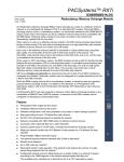
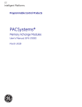
1
SmartX User Manual Version 1.68 24 August 2015 Revision History Revision Date Changes Name Version 1.3 05 November 2012 Updated website information. Added Technical Specifications and Ordering Codes. Erika Ladouceur Version 1.31 06 December 2012 Updated images. Erika Ladouceur Version 1.4 28 February 2013 Updated technical specifications Chris Bueley & Jehan Zouak Version 1.5 26 May 2013 Format revision and updates Jehan Zouak Version 1.6 26 August 2013 Minor edits Jehan Zouak Version 1.61 12 February 2014 Added UV•Xchange references Chris Bueley Version 1.62 16 July 2014 Added Ordering Codes Jehan Zouak Version 1.63 27 October 2014 Added Power Consumption Table Quinton Calverley Version 1.64 17 March 2015 Updated for SeaCast 4 Andrew Beak-Taylor Version 1.65 12 June 2015 Added Tu•Xchange technical specs Jehan Zouak Version 1.66 22 June 2015 Updated technical specifications Jehan Zouak Version 1.67 24 July 2015 Information for the UV option added Andrew Beak-Taylor Version 1.68 24 August 2015 Independent UV option updates Jehan Zouak User Manual for AML Oceanographic’s SmartX Table of Contents General Description of the Instrument .............................................................................................. 2 Where Do I Start? ............................................................................................................................ 3 Shipping & Receiving ....................................................................................................................... 4 Receiving an Instrument .............................................................................................................. 4 Returning an Instrument to the Factory........................................................................................ 4 Using the Instrument ........................................................................................................................ 5 Pressure Ratings ......................................................................................................................... 5 Pre-Deployment Procedures........................................................................................................ 5 Configuring Sampling Parameters Using SeaCast ...................................................................... 6 Configuring Sampling Parameters through the Terminal ............................................................. 6 Accounting for Atmospheric Pressure Variations at the Surface .................................................. 6 Monitoring Real Time Data .......................................................................................................... 7 Post-Deployment Procedures ...................................................................................................... 7 Configuring the Instrument for Data on Power Up ....................................................................... 8 Disabling Data on Power Up ........................................................................................................ 8 Smart•X with Independent UV ..................................................................................................... 9 Maintaining the Instrument ..............................................................................................................10 Periodic Maintenance .................................................................................................................10 Communications .............................................................................................................................11 PC Settings .................................................................................................................................11 Output Formats ...........................................................................................................................11 Default Output Format...........................................................................................................11 Default Example Outputs ......................................................................................................12 Support ...........................................................................................................................................14 Troubleshooting ..........................................................................................................................14 Contact AML Oceanographic ......................................................................................................16 Appendices .....................................................................................................................................17 Commands .................................................................................................................................17 Communications Commands ................................................................................................17 Sampling Rate Commands ...................................................................................................17 Output Format Commands....................................................................................................18 General Commands ..............................................................................................................19 Technical Specifications .............................................................................................................20 Ordering Codes ...............................................................................................................................24 Instruments .................................................................................................................................24 Sensors/Devices .........................................................................................................................24 Accessories ................................................................................................................................25 Warranty .........................................................................................................................................26 Technical Overview Drawings .........................................................................................................27 1 User Manual for AML Oceanographic’s SmartX General Description of the Instrument AML Oceanographic X•Series instruments and XchangeTM sensors are a major advancement in oceanographic instrumentation. Swappable and interchangeable sensors dramatically improve the capabilities of ocean instrumentation in the following ways: Change the instrument sensor types while at sea within seconds, and without tools. A CTD can be changed to a sound speed profiler by exchanging sensor heads. To optimize the resolution and accuracy of sensor data, sensors can be swapped to change the measurement range. For example, a 6000 dbar P•Xchange pressure sensor can be swapped with a 500 dbar P•Xchange sensor, and the salt water C•Xchange conductivity sensor can be swapped for a fresh water C•Xchange conductivity sensor. Sensors from one instrument can be swapped to another to maintain mission-critical capabilities. Calibrated sensors can be sent from the factory to the instrument. The instrument is not pulled from active duty for calibration. Spare sensors ensure that an instrument can be immediately returned to active duty after sustaining damage. All calibration and traceability data resides within each XchangeTM sensor. Calibration data for all sensors is instantly available from the instrument, and calibration certificates can be printed from AML Oceanographic’s SeaCast software whenever the instrument is connected. Logged data is stamped with sensor traceability and instrument configuration data. Only XchangeTM sensors are sent for calibration, leaving the instrument working in the field. Smart•X is the compact, multi-sensor, externally powered, real-time instrument of the X•Series family. It is designed primarily for AUV/ROV and sea chest operations. Supported communication protocols for Smart•X are RS-232 or RS-485. There are three configurations of Smart•X. Two are multi-parameter and the other is single sensor. These are listed below with a brief description. P1S2: Multi-parameter – this configuration is equipped with one primary Xchange™ sensor port (C•Xchange™ or SV•Xchange™) and two secondary Xchange™ sensor ports (T•Xchange™, P•Xchange™, or Tu• XchangeTM). Sampling rates are programmable by time (25 Hz to every 24 hours). This unit carries with it the complete benefits of an X•Series instrument. P1S1+UV (Independent UV option): Identical to the P1S2, but one of the secondary ports is dedicated to an independently-powered UV•Xchange operated by an internal Duty Cycle Control. This maximizes power savings without compromising biofouling control. P1S0: Single primary sensor - This configuration closely duplicates the original Smart SV as it is of similar form, fit, and function. It is often utilized when a replacement of a Smart SV is required for both size and data format requirements. For this style of instrument, please disregard reference to conductivity, temperature, pressure, and turbidity sensors in this manual. 2 User Manual for AML Oceanographic’s SmartX Where Do I Start? AML Oceanographic’s X•Series instruments ship with several manuals on the USB stick: An instrument manual (this Smart•X manual) providing an overview on how to use and maintain the instrument; A SeaCast manual providing instructions on how to use the software to configure the instrument and review instrument data; Xchange™ manuals (C•Xchange, SV•Xchange, P•Xchange, T•Xchange, Tu•Xchange, and UV•Xchange) providing overviews on how to install and maintain each of the Xchange™ sensors; If you are configuring an instrument for field use or lab testing, begin with the SeaCast manual. If you are performing instrument maintenance, begin with the instrument manual. If you are planning to swap an Xchange™ sensor, read the Xchange™ manual corresponding to your sensors. If Smart•X is equipped with UV•Xchange, refer to the UV•Xchange manual. 3 User Manual for AML Oceanographic’s SmartX Shipping & Receiving Receiving an Instrument When receiving an instrument, perform the following steps to ensure the instrument will be ready for deployment when required: Inspect the shipping container, looking for signs of damage. Damage to the shipping container could indicate damage to the instrument inside. The shipping package should include all of the following items o Smart•X instrument o Data/Power cable o Black dummy plug o One primary sensor blanking plug o Two secondary sensor blanking plugs o USB stick with manuals and documentation Inspect for damage o Check the cable for slices or gouges o Check the connector sockets for corrosion, dirt, and salt deposits o Check the pressure case for dents and scrapes o Check the sensors for cracks or bends Ensure all the Xchange™ sensors are installed tightly. The blue locking sleeve should be tight and sitting less than 1 mm from the instrument end cap. Connect the instrument to a computer with the data cable and perform a scan or monitor if using SeaCast. Returning an Instrument to the Factory If shipping for repair or recalibration, obtain an RMA number from the service centre. Pack the instrument in its original shipping box to prevent damage during shipping. An RMA number can be requested using the contact options given in the Support section of this manual. 4 User Manual for AML Oceanographic’s SmartX Using the Instrument Pressure Ratings Pressure ratings are given for Xchange™ sensors and the entire instrument. Deployments should never exceed the lower of these two pressure ratings. For example, a 500m instrument equipped with a 6000 dbar (0-6000m) P•Xchange™ sensor is limited to deployments of 500m depth or less. Similarly, a 6000m instrument equipped with a 500 dbar (0-500m) P•Xchange™ sensor is also limited to deployments of 500m depth or less. It is desirable to optimize the accuracy of pressure measurements by using a P•Xchange™ sensor with a pressure range that closely matches the depth of the deployment. Caution: Do not exceed the specified pressure ratings of the P•Xchange™ sensor, Turbidity•Xchange™ sensor, or the instrument housing. Overpressure can result in damage to the sensors and the instrument. Pre-Deployment Procedures Upon Receipt o Use the Shipping and Receiving instructions to verify the condition of the instrument. o Verify that all sensor calibrations are valid for the duration of the deployment. If not, swap the Xchange™ sensors for sensors with valid calibrations or send the Xchange™ sensors to a service centre for recalibration. o Lightly lubricate the underwater connectors with 3M silicone spray or equivalent. Before leaving the jetty o If applicable, verify the P•Xchange™ pressure range is correct for the deployment. o Connect the instrument to a computer using the data cable. Caution: Install blanking plugs in all unused sensor ports prior to deployment. Failure to install blanking plugs will result in damage to the connectors. Primary Xchange™ mount blanking plug Secondary Xchange™ mount blanking plug 5 User Manual for AML Oceanographic’s SmartX Configuring Sampling Parameters Using SeaCast SeaCast is free software provided for use with AML Oceanographic instruments. It can be used to set up an instrument for profiling or monitoring data, as well as downloading, graphing, and exporting the collected data. Full details on the instrument configuration process and the software’s capabilities can be found in the SeaCast manual. Configuring Sampling Parameters through the Terminal Instruments can also be configured for deployment using a terminal emulation program like HyperTerminal, RealTerm, or Tera Term. Communications with the instrument must be established using the correct communications port and settings. The communications settings are 8 data bits, 1 stop bit, no parity, no flow control, and the desired baud rate. The following steps must be completed by issuing text commands: Step Initialize Memory (erases instrument memory) Set Log File Name Set Instrument Time & Date Possible Commands INIT SET LOG filename.txt SET TIME hh:mm:ss SET DATE mm/dd/yy SET SAMPLE RATE CONTINUOUS SET SAMPLE RATE 5/s SET P INC 1 SET SOUND INC 2 Set Sampling Parameters The above table provides example commands only; many additional sampling regimes can be established using available commands. Please consult the Commands section of the Appendix for full syntax details on the commands you wish to use. Accounting for Atmospheric Pressure Variations at the Surface Climate and altitude changes can create fluctuations in atmospheric (barometric) pressure. AML's pressure sensors are sensitive enough to detect these variations. When this happens, the instrument's pressure channel may not read exactly zero when data is taken prior to submersion in the water. Nearly all absolute pressure sensors experience atmospheric pressure offsets if they are sufficiently sensitive. To compensate for this atmospheric pressure offset, AML instruments have the ability to reset the pressure sensor's zero point. This can be initiated using AML Oceanographic SeaCast software or a Terminal emulator command. The compensation does not affect the calibration of the pressure sensor, and can be turned off or recalculated at any time. The compensation factor is applied through the entire calibrated pressure range. Once the atmospheric pressure compensation is applied, it will be applied to all pressure sensor data until it is turned off or recalculated. The setting is written to memory, so it remains set when the instrument is powered down. 6 User Manual for AML Oceanographic’s SmartX Using SeaCast Refer to the SeaCast User Manual for instructions on enabling "Zero Depth." Using a Terminal Emulator Establish serial communications with the instrument on your computer. Refer to the Communications section of this manual for more information. Once the connection is established, ensure the instrument is stationary, and is not submerged in water. To turn ON Atmospheric pressure compensation, issue the ZERO ON command. This will calculate and apply the offset required to compensate for current atmospheric pressure conditions. To turn OFF Atmospheric pressure compensation, issue the ZERO OFF command. This will disable the offset. Issuing the ZERO command again will calculate a new offset based on current conditions. Monitoring Real Time Data Ensure the pre-deployment procedures have been completed (see page 5). Ensure that the desired sampling settings have been selected and applied. Plug the data/power cable into the instrument. If you power the instrument over a long cable, please note the following: o Voltage drop due to cable resistance increases with cable length. The voltage drop on a standard AML cable, with a standard Smart•X, is about 2 volts per 100m of cable while sampling and 0 volts per 100m when in low power mode. o The instrument’s low voltage warning triggers at 9.9 volts or less. o The instrument’s auto shutdown triggers when supplied with 8.0 volts or less. o The instrument’s maximum voltage is 26 volts. o The voltage at the instrument, while sampling, must be above the shutdown level for the instrument to operate. With the instrument in air, use the ZERO command to zero the barometric pressure offset (P•Xchange™ only). Securely attach the cable to the instrument. Lower the instrument until it is just submerged. Keep the instrument at this depth for 2 minutes prior to beginning the cast. This allows the sensors time to wet and the pressure case to shed heat. Begin monitoring data using SeaCast or HyperTerminal. Send the instrument down to the desired depth and return it to the surface. Note that with Smart•X in the typical, vertical orientation, the downcast is usually more accurate than the upcast data since the downcast measurements are not contaminated by the thermal shedding from the pressure case. Post-Deployment Procedures When the instrument is pulled from the water it should be rinsed in fresh water. Dry the area around the connectors with a clean cloth or compressed air prior to disconnecting the plugs or cables. Do not blow compressed air into the 7 User Manual for AML Oceanographic’s SmartX Pressure•Xchange™ sensor. Doing so may damage the sensitive pressure transducer diaphragm. Remove the shorting plug or cable. Place the dummy plug in the connector to protect it. Dry the instrument and stow it securely. Configuring the Instrument for Data on Power Up Perform the following steps: Open a terminal emulation program such as HyperTerminal. Ensure the serial port has been selected in the program. If the instrument has been set to a specific baud rate with the SET DETECT command, the terminal emulation program must be configured for that baud rate. Connect the instrument to the computer using the data/power cable. Using the terminal emulation program, issue the following commands to the instrument: o SET STARTUP NOHEADER (disables the power up header information) o SET STARTUP MONITOR (enables data output on power up) o SET SAMPLE RATE 10/S (sets the desired sampling rate) o SET DETECT 07 (sets fixed 38400 baud rate) Note: Details on the SET DETECT command can be found in the appendix. Unplug the data/power cable from the instrument to turn the instrument off. Plug the data/power cable into the instrument to turn the instrument on. Disabling Data on Power Up Perform the following steps: Open a terminal emulation program such as HyperTerminal. Ensure the serial port has been selected in the program. If the instrument has been set to a specific baud rate with the SET DETECT command, the terminal emulation program must be configured for that baud rate. Connect the instrument to the computer using the data/power cable Unplug the data/power cable from the instrument to turn the instrument off. Hold down the < ENTER > key. Plug the data/power cable into the instrument to turn the instrument on. Release the <ENTER> key once the prompt ‘>’ is displayed. Using the terminal emulation program, issue the following commands to disable data on power up: o SET STARTUP HEADER (enables the power up header information) o SET STARTUP PROMPT (disables data output on power up) o SET SAMPLE RATE 10/S (selects the desired sampling rate) o SET DETECT A7 (sets 10 autobaud attempts then defaults to 38400 baud) Note: Details on the SET DETECT command can be found in the appendix. Unplug the data/power cable from the instrument to turn the instrument off. 8 User Manual for AML Oceanographic’s SmartX Smart•X with Independent UV The independent UV option is offered for situations where economic power usage is critical but biofouling protection is still desired. By running the UV independently through a DCC the instrument can take advantage of all its power saving saving features, shutting down between measurements while the UV•Xchange continues to prevent fouling uninterrupted on a different power source. If the UV option is selected, the Smart•X will be configured as a P1S1+UV, which is a P1S2 where one of the secondary ports is dedicated to UV•Xchange. This port is marked with “UV ONLY.” Configuration of the Duty Cycle Controller The default setting for the DCC is a repeating pattern of 20 minutes on and 20 minutes off. This can be configured at user request for any combination of 2-minute increments in a repeating 120minute period. The on-off timer begins immediately once the controller is supplied with power. Note: If powered through the dedicated port, configuration options for the UV•Xchange will not be accessible through SeaCast. Power Power to the UV port is independent from the rest of the instrument. If the independent UV option is selected, two pins on the connector that are normally unused are activated for this purpose. Pin 5 Pin 6 UV VDC UV GND Power must be supplied continuously. When the DCC is in an "on" cycle, power is passed through to the device connected to the output. No power is passed to the output during an "off" cycle. The timing board itself consumes less than 0.1mA during both "on" and "off" cycles. 9 User Manual for AML Oceanographic’s SmartX Maintaining the Instrument Periodic Maintenance Periodic preventative maintenance will prolong the life of the instrument. The following steps are recommended: If the instrument is very dirty or oily, allow it to soak in warm, soapy water before cleaning with a rag or soft brush. When finished, rinse with fresh water to remove any residual soap or dirt. Before each use: o Check for proper installation of all Xchange™ sensors. o Check for nicks and cuts on the cable. After each use: o Clean and rinse the instrument using fresh water. o Dry the instrument completely, and store it in a cool, dry place. Monthly: o Lightly lubricate the connector contacts with 3M silicone spray or equivalent. Avoid the use of grease. It can create internal pressure and push past the connector seals on the pins. o Lubricate the end cap retainer rings with silicone grease. Yearly: o Send the instrument or Xchange™ sensors to a service centre for diagnostics and re-calibration. 10 User Manual for AML Oceanographic’s SmartX Communications PC Settings Smart•X will communicate with both RS-232 and RS-485 serial connections. The computer to which the instrument is connected must be set up as follows: 8 bits 1 stop bit No parity No hardware flow control Baud rate of 600, 1200, 2400, 4800, 9600, 19,200, or 38,400 baud After power up, the Smart•X will wait for an ASCII carriage return. The instrument will automatically detect whether communications are RS-232 or RS-485 as well as the baud rate. Output Formats Output formats can be modified. If the required modifications are not supported by the commonly used command list in the next section, please contact the factory for support with custom output formats. Formatting can be changed in the following ways: The number of decimal places for each channel Turn on or off o date and time o calculated parameters (Salinity and Density) o battery voltage o power up information (header) o automatic monitoring on power up Default Output Format The output from Smart•X is space delimited values. The following table shows the output units for each Xchange™ sensor: Sensor Units Default Format SV•Xchange™ m/s 1234.567 Conductivity•Xchange™ mS/cm 12.346 Pressure•Xchange™ dbar 1234.56 Temperature•Xchange™ C 12.345 Turbidity•Xchange™ NTU 1234.56 11 User Manual for AML Oceanographic’s SmartX The default data channel outputs with all calculated parameters turned on are: SV, P, T Sensors Sound velocity m/s Time hh:mm:ss.ss Pressure dbar Temperature C Sound velocity m/s Pressure dbar Temperature C Density kg/m3 Salinity ppt Temperature C Density kg/m3 Salinity psu C, P, T Sensors Conductivity mS/cm Pressure dbar Temperature C Time hh:mm:ss.ss Conductivity mS/cm Pressure dbar Sound velocity m/s Note: These are examples of the default configurations. Your data channel outputs will be entirely dependent on which XchangeTM sensors are installed. Default Example Outputs Keyboard inputs in the output capture shown below are in bold type. Smart.X Version 4.09 SN:8882 AML Oceanographic Ltd. >scan 1473.924 0000.182 >set scan time >set >set 17.260 scan salinity scan density >scan 00:00:56.25 1473.912 >set scan notime 0000.163 17.258 00.226 >set scan nosal >set scan noden >scan 1473.916 >monitor 1473.912 1473.920 1473.915 1473.926 1473.921 1473.919 1473.920 1473.916 1473.915 1473.913 1473.909 1473.916 0000.182 17.256 0000.182 0000.182 0000.185 0000.178 0000.178 0000.182 0000.185 0000.182 0000.178 0000.178 0000.182 0000.185 17.254 17.255 17.254 17.254 17.255 17.256 17.257 17.258 17.257 17.256 17.256 17.256 12 0998.907 User Manual for AML Oceanographic’s SmartX >detect Detecting Sensors 1: SV-C.Xchange SV.X SN 131194 01/22/10 SN: 65535 2: P-T.Xchange P.X SN 145721 08/21/09 T.X SN 400046 11/17/09 SN: 65535 Detection complete >>display options [Instrument] Type=Smart.X EmulationMode=disabled UseCustomHeader=yes SN=8882 Firmware=V4.09 SampleUnits=continuous SampleInterval=0 PressureInc=0.00 SoundInc=0.00 TestLog=test.raw Date=01/01/00 Time=00:00:00 MemorySize=0.0 MB MemoryUsed=0.0 MB DisplayTime=no DisplayDate=no DisplaySalinity=no DisplayDensity=no DisplaySoundVelocity=no DisplayBattery=no RelayMode=auto detection RealtimeLogging=no LoggingTimeout=0 StartupDelay=20 DisplayHeader=yes StartupMode=prompt CharacterReception=yes LoggingBreakMode=no DetectionMode=A3 BatteryACoefficient=+3.500000E-01 BatteryBCoefficient=+2.500000E-02 ShutDownVoltage=6.5 WarningVoltage=not applicable PressureOffset=0.00 UsePressureOffset=no SoundVelocityThreshold=1375.00 DelimterMode=Space SensorDetectionMode=Once Traceability=no SkipPowerOff=no [Slot 1] SensorName=SV-C.Xchange SV.X SN 131194 01/22/10 BoardSN=65535 [Slot 2] SensorName=P-T.Xchange P.X SN 145721 08/21/09 T.X SN 400046 11/17/09 BoardSN=65535> 13 User Manual for AML Oceanographic’s SmartX Support Troubleshooting Instrument fails to communicate: Is the connector damaged? Check the cables o Is the data/power cable connected to the instrument and computer? o Are there any cuts in the cable? o If using a cable other than an AML cable, it should be configured as a null modem cable. o If using multiple cable lengths, the extensions should not be configured as null modem cables. If using external power over a long cable, check the voltage drop over the cable. Measure the voltage across a 10 watt, 27Ω, resistor across pins 2 and 3 of the cable. The voltage must be above 8 volts. Are the communication settings in the program used on the computer correct? o Comm port selection o 8 bits o 1 stop bit o No parity o No hardware flow control o Baud rate between 600 and 38,400 baud Are the communication settings in the instrument correct? o Was the instrument specifically set to one baud rate last time? If so, use that baud rate to resume communications. o Was the instrument set to only RS-232 or only RS-485 last time? If so, resume communications in the required protocol. o Was the instrument set to RX OFF last time? If so, a carriage return must be sent to the instrument immediately after power is applied to interrupt this mode. o Was the instrument set to monitor on power up mode? If so, a carriage return must be sent to the instrument immediately after power is applied to interrupt this mode. To interrupt monitor on power up, hold down the ENTER key while applying power to the instrument. Instrument generates noisy data: Is the connector damaged, dirty, or corroded? If connected to external power, is there noise on the power supply? Switch-mode power supplies are common sources of noise. Nearby EMI sources such as electric motors, generators, and transformers can create noise. If possible, move the instrument and its cables away from the noise source. Are the sensor/s clean? Are there bubbles on or in the sensor/s? Are the sensor/s damaged? 14 User Manual for AML Oceanographic’s SmartX Is there something nearby affecting the water temperature? SeaCast fails to recognize a sensor: Be sure to download the latest version of SeaCast. SV•Xchange data does not match CTD-calculated SV: Owing to the error associated with each individual sensor and Chen and Millero’s equation1, sound velocity calculated from CTD values will fall within approximately ±0.4 m/s of the actual value 95% of the time. It is not uncommon to see differences of this size between directly measured sound velocity and CTD-calculated sound velocity. Chen-Tung Chen and Frank J. Millero, “Speed of sound in seawater at high pressures,” The Journal of the Acoustical Society of America 62, no. 5 (1977): 1129-1135. 1 15 User Manual for AML Oceanographic’s SmartX Contact AML Oceanographic Service To request an RMA or technical support Email: [email protected] Phone: 1-250-656-0771 Phone: 1-800-663-8721 (NA) Fax: 1-250-655-3655 Sales For all general sales inquiries Email: [email protected] Phone: 1-250-656-0771 Phone: 1-800-663-8721 (NA) Fax: 1-250-655-3655 Website http://www.AMLoceanographic.com Customer Portal My AML Oceanographic is AML's online data centre. This secure area within our website is designed to offer one easy location for interested individuals and organizations - distributors, customers, prospects, and other members of our community - to manage their interactions with AML. My AML Oceanographic will allow you to: View and manage your assets (instruments and sensors) Consult instrument diagnostic summaries View and download calibration and conformity certificates View and manage your technical support cases Consult and download sales estimates, sales orders, and invoice copies View account balances and generate account statements Assess inventory availability at AML To access the Customer Portal, please navigate to the Support button - located on the top right of the AML Oceanographic home page - select Customer Centre from the options on the drop down menu and follow the instructions provided. Mailing and Shipping Address AML Oceanographic 2071 Malaview Ave. Sidney, BC, Canada V8L 5X6 16 User Manual for AML Oceanographic’s SmartX Appendices Commands When using SeaCast, the full command set is not usually necessary. However, text commands are available. Below is a listing of commonly used commands. Note that some commands are only available on instruments equipped with the applicable Xchange™ sensors. Communications Commands Command SET FORCE 232 SET FORCE 485 SET FORCE AUTO DISPLAY FORCE DISPLAY DETECT SET DETECT a b Description Sets com mode to RS-232. Power must be cycled for changes to take effect. Sets com mode to RS-485. Power must be cycled for changes to take effect. Sets for auto-detection of RS-232 or RS-485 comms. Note that if instrument is not connected to a com port on power up, it assumes RS-485 operation & will remain in that mode until powered down. Displays current com mode (i.e. RS232, RS485, AUTO) Displays the baud rate detection settings. Sets the baud rate detection. “a” sets the number of autobaud detection attempts before the instrument reverts to the default baud rate set by “b”. Setting ‘a’=0 forces the instrument to a fixed baud rate determined by “b.” “b”= 1 = 600 baud 4 = 4800 baud 7 = 38400 baud 2 = 1200 baud 5 = 9600 baud 8 = 57600 baud 3 = 2400 baud 6 = 19200 baud 9 = 115200 baud Requires Sampling Rate Commands Command DISPLAY SAMPLE RATE SET SAMPLE n t Description Displays the time-based sampling rate Sets the desired sampling rate. “n” is a number and “t” is the time units. Using the slash ( / ) character should be read as "per." For instance, 5 s means sampling happens every 5 seconds. 5/s means 5 samples per second. Examples are: SET S C sets the sampling to continuous (25 Hz) SET S 5 /s 5 samples per sec SET S 1 s Sample 1 time every 1 second SET S 2 /m 2 samples per minute SET S 5 m Sample 1 time every 5 minutes SET S 2 /h 2 samples per hour SET S 24 h Sample 1 time every 24 hours 17 Requires User Manual for AML Oceanographic’s SmartX Output Format Commands Command DISPLAY SCAN SET SCAN NODENSITY Description Displays current scan options. Turns the calculated density channel off. SET SCAN DENSITY Turns the calculated density channel on. SET SCAN NOSALINITY Turns the calculated salinity channel off. SET SCAN SALINITY Turns the calculated salinity channel on. SET SCAN NOSV Turns the calculated sound velocity channel off, removing it from the instrument output scans. Current salinity display status is viewable using DIS SCAN. Turns the calculated sound velocity channel on, allowing it to be present in instrument output scans. Current salinity display status is viewable using DIS SCAN. This is only available when C,P, and T sensors are attached. Enables displaying time in data scan. Disables time from being displayed in data scan. Displays the power up output settings. Sets the instrument to wait for user commands on power up. SET SCAN SV SET SCAN TIME SET SCAN NOTIME DISPLAY STARTUP SET STARTUP PROMPT SET STARTUP SCAN SET STARTUP MONITOR SET STARTUP NOHEADER SET STARTUP HEADER Sets the instrument to output one scan on power up, and then wait for a user command. Sets the instrument to start monitoring data on power up. Disables the instrument identification header output on power up. Enables the instrument identification header output on power up. 18 Requires C•X, T•X, and P•X or SV•X, T•X, and P•X C•X, T•X, and P•X or SV•X, T•X, and P•X C•X, T•X, and P•X or SV•X, T•X, and P•X C•X, T•X, and P•X or SV•X, T•X, and P•X C•X, T•X, and P•X C•X, T•X, and P•X User Manual for AML Oceanographic’s SmartX General Commands Command SCAN MONITOR VERSION DISPLAY OPTIONS ZERO ZERO OFF DIS TIME SET TIME hh:mm:ss.ss DETECT TALK n CTRL+C Description Measures and outputs one scan of data. Scans at the set sampling rate. Displays the instrument identification header. Displays the instrument status and user settings. Corrects the barometric offset to set zero pressure at surface for current barometric pressure. Disables barometric offset. Displays current time. Time format is hh:mm:ss.ss Sets instrument time using 24 hour clock in format hh:mm:ss.ss Checks each slot in logger board to identify what is plugged in and displays sensor / board type and serial number or “empty” for each slot. Enables communications directly with a sensor board via the logger board, where n = value from 1-3 that identifies the slot number of the board to be communicated with. See DETECT command. Press CTRL key and C key at same time to exit sensor board talk mode and return to logger communications. 19 Requires P•X P•X User Manual for AML Oceanographic’s SmartX Technical Specifications Sensors Primary Xchange™ Sensors Type Range Accuracy Precision Resolution Response Time Conductivity•Xchange™ 0 to 2 mS/cm 0.01 mS/cm 0.003 mS/cm 0.001 mS/cm 25 ms at 1 m/s flow rate Conductivity•Xchange™ 0 to 70 mS/cm 0.01 mS/cm 0.003 mS/cm 0.001 mS/cm 25 ms at 1 m/s flow rate Conductivity•Xchange™ 0 to 90 mS/cm 0.01 mS/cm 0.003 mS/cm 0.001 mS/cm 25 ms at 1 m/s flow SV•Xchange™ 1375 to 1625 m/s 0.025 m/s 0.006 m/s 0.001 m/s 47 µs Secondary Xchange™ Sensors Type Range Accuracy Precision Resolution Response Time Temperature•Xchange™ -2°C to 32°C 0.005°C 0.003°C 0.001°C 100 ms Temperature•Xchange™ -5°C to 45°C 0.005°C 0.003°C 0.001°C 100 ms Temperature•Xchange™ 0°C to 65°C 0.005°C 0.003°C 0.001°C 100 ms Pressure•Xchange™ 50, 100, 200, 500, 1000, 2000, 4000, 5000, 6000 dbar 0.05%FS 0.03%FS 0.02%FS 10 ms Turbidity•Xchange™ 0-100 NTU 0.1 NTU 0.1 NTU 0.01 NTU < 0.7s Turbidity•Xchange™ 0-400 NTU 0.2 NTU 0.2 NTU 0.01 NTU < 0.7s Turbidity•Xchange™ 0-1000 NTU 0.5 NTU 0.5 NTU 0.1 NTU < 0.7s Turbidity•Xchange™ 0-3000 NTU 1 NTU 1 NTU 0.1 NTU < 0.7s 20 User Manual for AML Oceanographic’s SmartX Calculated Parameters Type Required Sensors Equation Accuracy Range Salinity C•X, T•X, P•X TEOS10 ±0.010 psu 0 to 42 psu Salinity (from SV) SV•X, T•X, P•X AML ‘07 ±0.035 ppt 0 to 42 ppt Density C•X, T•X, P•X TEOS10 ±0.027 kg/m3 990 to 1230 kg/m3 Density (from SV) SV•X, T•X, P•X TEOS10 ±0.051 kg/m3 990 to 1230 kg/m3 SV (from CTD) C•X, T•X, P•X Chen & Millero ‘772 0.5 m/s --- Electrical Mother Board o Two dedicated slots Primary Xchange™ sensor slot Secondary Xchange™ sensor slot Sensor Boards o Sound Velocity or Conductivity Xchange™ sensor board o Pressure, Temperature, or Turbidity Xchange™ sensor board Auto detect RS232 or RS485 (½ duplex ASCII) Autobaud to 38,400 Power External Power Supply: 8 to 26 VDC 2 Chen and Millero, “Speed of sound in seawater at high pressures,” 1129-1135. 21 User Manual for AML Oceanographic’s SmartX Current Draw at 12VDC Primary Sensor Secondary Sensor Secondary Sensor Current Draw (mA) C•X - - 122 C•X P•X - 129 C•X T•X - 138 C•X P•X T•X 145 C•X T•X *UV•X 383 SV•X - - 120 SV•X P•X - 127 SV•X T•X - 132 SV•X P•X T•X 142 SV•X P•X Tu•X 148 - T•X - 135 - P•X - 127 - P•X Tu•X 146 - Tu•X - 130 * Single Stack 3mW UV LED module Pressure Case Environmental Limits o Storage: -40°C to 60°C o Usage: -20°C to 45°C Housing Status Type Standard Delrin Depth Rating 500 m Optional Titanium 6000 m Diameter Length 76mm (2.98”) 565mm (22.3”) Weight (in water) 0.23 Kg (0.5 lbs) Weight (in air) 0.82 Kg (1.8 lbs) 1.35 Kg (3.0 lbs) 1.94 Kg (4.3 lbs) Connectors Type Status Pins Sex Material Manufacturer Bulkhead Bulkhead On Delrin housings On titanium housings Micro 6 Micro 6 Female Female SS316 Titanium Subconn Subconn 22 User Manual for AML Oceanographic’s SmartX Sampling Capabilities Frequency o Time: From 25 samples per second to 1 sample per hour Configurations o Single scan or continuous output o On command or autonomous on power up Included Items Smart•X instrument 2m Data/Power Pigtail Black dummy plug One primary sensor blanking plug Two secondary sensor blanking plugs USB stick with manuals and documentation Sensor protection cage Software SeaCast 23 User Manual for AML Oceanographic’s SmartX Ordering Codes Instruments PDC-SMX-P1S2-05 Smart•X, 500 dbar, Delrin pressure housing PDC-SMX-P1S2-60 Smart•X, 6000 dbar, Titanium pressure housing PDC-SMX-P1S2-VIM-05 Smart•X, 500 dbar, Delrin pressure housing, Right Angle AUV Mount Smart•X, 500 dbar, Delrin pressure housing. Used as Smart SV PDC-SMX-P1S0-05 replacement. Smart•X, 6000 dbar, Titanium pressure housing. Used as Smart SV PDC-SMX-P1S0-60 replacement. PDC-SMX-P1S1UV-05 Smart•X, 500 dbar, Delrin pressure housing, dedicated UV port Sensors/Devices XCH-SV-STD XCH-SV-1120 XCH-SV-0520 XCH-CND-RA002 XCH-CND-RA070 XCH-CND-RA090 XCH-CND-ST002 XCH-CND-ST070 XCH-TMP-n232 XCH-TMP-n545 XCH-TMP-065 XCH-PRS-0050 XCH-PRS-0100 XCH-PRS-0200 XCH-PRS-0500 XCH-PRS-1000 XCH-PRS-2000 XCH-PRS-4000 XCH-PRS-5000 XCH-PRS-6000 XCH-PRS-6000-T065 XCH-TRB-0100-03 XCH-TRB-0100-05 XCH-TRB-0400-03 XCH-TRB-0400-05 XCH-TRB-1000-03 XCH-TRB-1000-05 XCH-TRB-3000-03 SV•Xchange™ (1375-1625m/s) Range *Replaces XCH-0002* SV•Xchange™ (1100-2000m/s) Range SV•Xchange™ (500-2000m/s) Range C•Xchange™ Right Angle, Ultra Freshwater (0-2mS/cm) Range C•Xchange™ Right Angle, Oceanographic (0-70mS/cm) Range C•Xchange™ Right Angle, Oceanographic (0-90mS/cm) Range C•Xchange™ Straight, Oceanographic (0-70mS/cm) Range C•Xchange™ Straight, Ultra Freshwater (0-2mS/cm) Range T•Xchange™ (-2 to 32 C) Range T•Xchange™ (-5 to 45 C) Range T•Xchange™ (0 to 65 C) Range P•Xchange™ 50 dbar P•Xchange™ 100 dbar P•Xchange™ 200 dbar P•Xchange™ 500 dbar P•Xchange™ 1000 dbar P•Xchange™ 2000 dbar P•Xchange™ 4000 dbar P•Xchange™ 5000 dbar P•Xchange™ 6000 dbar P•Xchange™ 6000 dbar, Extended temperature calibration from 0-65 C Tu•Xchange™ (0-100 NTU) Range, 300m Tu•Xchange™ (0-100 NTU) Range, 500m Tu•Xchange™ (0-400 NTU) Range, 300m Tu•Xchange™ (0-400 NTU) Range, 500m Tu•Xchange™ (0-1000 NTU) Range, 300m Tu•Xchange™ (0-1000 NTU) Range, 500m Tu•Xchange™ (0-3000 NTU) Range, 300m 24 User Manual for AML Oceanographic’s SmartX XCH-TRB-3000-05 XCH-UV-LLLV XCH-UV-V Tu•Xchange™ (0-3000 NTU) Range, 500m UV•Xchange, 3 lower power sideways facing modules + vertical module UV•Xchange, single vertical module Accessories MBR-SMX-STD DFR-SMX-1PT DFR-SMX-4PT Smart•X mounting bracket assembly Smart•X Suspension Bar Assembly, 1 Pt. w/Clamps Smart•X Protection Frame Assembly, 4 Pt w/Clamps 25 User Manual for AML Oceanographic’s SmartX Warranty AML Oceanographic warrants the instrument for a period of two years from the date of delivery. AML will repair or replace, at its option and at no charge, components which are found to be defective. The warranty applies only to the original purchaser of the instruments. The warranty does not apply if the instrument has been damaged, by accident or misuse, and is void if repairs or modifications are made by any other than authorized personnel. This warranty is the only warranty given by AML. No warranties implied by law, including but not limited to the implied warranties of merchantability and fitness for a particular purpose shall apply. In no event will AML be liable for any direct, indirect, consequential, or incidental damages resulting from any defects or failure of performance of any instrument supplied by AML. 26 User Manual for AML Oceanographic’s SmartX Technical Overview Drawings 27 THE INFORMATION CONTAINED IN THIS DRAWING IS THE SOLE PROPERTY OF AML OCEANOGRAPHIC LTD. ANY REPRODUCTION IN PART OR WHOLE WITHOUT THE WRITTEN PERMISSION OF AML OCEANOGRAPHIC LTD IS PROHIBITED REVISION TABLE REV A DESCRIPTION INCREASED LENGTH, ADDED UV•X BY DATE C.B. 12 FEB/14 306.8 12.08 191.8 7.55 27.4 1.08 Smart X P1S0 with SV Xchange AML Part Numbers: • Smart X P1S0: PDC-SMX-P1S0-05/60 • SV Xchange: XCH-SV-STD Materials: • Delrin - 500m Pressure Rating • Titanium - 6000m Pressure Rating 45.7 1.80 A 425.8 16.77 242.1 9.53 181 7.13 69.9 2.75 45.7 1.80 68.6 2.70 Smart X P1S2 AML Part Numbers: • Smart X P1S2: • SV Xchange: • C Xchange: • P Xchange: • T Xchange: PDC-SMX-P1S2-05/60 XCH-SV-STD XCH-CND-RA[range] XCH-PRS-[range] XCH-TMP-[range] Materials: • Delrin - 500m Pressure Rating • Titanium - 6000m Pressure Rating Smart X - CTD Configuration Smart X - SVTP Configuration Smart X - CP,UV Configuration Mass Model Smart SV Smart SV&T Smart X SV&T Configuration (Flared) Smart SV&P Smart X SV&P Configuration (Flared) Smart SVT&P Smart X SVT&P Configuration (Flared) Smart CTD (Flared) Delrin .75lbs (.34 kg) .81 lbs (.37 kg) 1.79 lbs (.81 kg) .89 lbs (.40 kg) 1.77 lbs (.80 kg) .90 lbs (.41 kg) 1.873 lbs (.85 kg) 1.74 lbs (.79 kg) Titanium 1.86 lbs (.84 kg) 2.02 lbs (.92 kg) 4.19 lbs (1.90 kg) 2.24 lbs (1.02 kg) 4.17 lbs (1.89 kg) 2.24 lbs (1.02 kg) 4.28 lbs (1.94 kg) 4.14 lbs (1.88 kg) TITLE: Smart X Mechanical Overview DRAWN 2071 Malaview Avenue W., Sidney B.C. Canada V8L 5X6 (250) 656 0771 Fax: (250) 655 3655 TOLERANCES: ANGLES: FRACTIONS: HOLE SIZES: 0.00: 0.000: 1 1/32 0.005(0.13) 0.015(0.38) 0.005(0.13) UNLESS OTHERWISE SPECIFIED: ORIGINAL SCALE:1:5 DATE I.L. 3rd ANGLE PROJECTION REV MC2-GA-03396 NOV 26/10 DIM'S ARE IN INCHES (MM) SURFACE FINISH: 63 DRAWING NO.: SIZE B MATERIAL: AML NO. N/A Delrin or Titanium SLD FILE NO.: MC2-GA-03318 SHEET NO. Sheet 1 of 2 THE INFORMATION CONTAINED IN THIS DRAWING IS THE SOLE PROPERTY OF AML OCEANOGRAPHIC LTD. ANY REPRODUCTION IN PART OR WHOLE WITHOUT THE WRITTEN PERMISSION OF AML OCEANOGRAPHIC LTD IS PROHIBITED REVISION TABLE REV DESCRIPTION DATE BY SMART AND SMART-X ELECTRICAL INTERFACE SPECIFICATION RS-232 COMMUNICATIONS Smart/Smart X Electronics Pin Signal - Rx Ground Power + Signal - Tx N/C N/C N/C 1 2 3 4 5 6 Ground White Black Red Green Blue Brown Screen Pin 9 Pin "D" Connector 3 5 2 N/C N/C N/C Power + MCBH-6-FS Bulkhead Face View 1 2 6 NOTE: SMART INSTRUMENTS ARE CONFIGURED AT THE FACTORY FOR RS-232 OR RS-485. CONSULT THE SMART OR SMART X USER MANUAL FOR INSTRUCTIONS ON MAKING CHANGES TO YOUR INSTRUMENT'S COMMUNICATION PROTOCOL. 5 3 4 RS-485 COMMUNICATIONS Smart/Smart X Electronics Pin Signal - DO (B) Ground Power + Signal - DO! (A) N/C N/C N/C 1 2 3 4 5 6 Ground White Black Red Green Blue Brown Screen Pin 9 Pin "D" Connector 3 5 2 N/C N/C N/C Power + TITLE: Smart Communications Overview DRAWN 2071 Malaview Avenue W., Sidney B.C. Canada V8L 5X6 (250) 656 0771 Fax: (250) 655 3655 TOLERANCES: ANGLES: FRACTIONS: HOLE SIZES: 0.00: 0.000: 1 1/32 0.005(0.13) 0.015(0.38) 0.005(0.13) UNLESS OTHERWISE SPECIFIED: ORIGINAL SCALE:1:4 DATE I.L. 3rd ANGLE PROJECTION REV MC2-GA-03396-A NOV 26/10 DIM'S ARE IN INCHES (MM) SURFACE FINISH: 63 DRAWING NO.: SIZE B AML NO. N/A MATERIAL: SLD FILE NO.: 9-pin D-sub Female SHEET NO. Sheet 2 of 2 D C B A 1 2 A REV 1 4 2 3 1 Female LEMO Solder Cup View UV•X LED Module 5 6 4 1 SHIELD RED Changed Text Description 3 2 Male MCBH6M Face View BROWN BLUE GREEN RED BLACK WHITE 3 - + 2 PWR IN KDC By July 16/15 Date SHIELD BLACK SHIELD BLACK Tabloid Size: Date: 8/25/2015 A Title 3 Time: 8:05:27 AM of 1 Revision: A Sheet 1 Number: MC7-EA-04020-A 4 1 4 4 AML Oceanographic 2071 Malaview Ave Sidney BC Canada V8L 5X6 3 2 Male LEMO Solder Cup View MCX Instrument With Internal DCC Wiring Diagram WHITE SUB-G0749 RED - PWR IN - PWR OUT PWR OUT WHITE LEMO Cable SHIELD BLACK RED RED Tx PWR+ GND Rx RED SUB-G0753 AML Instrument + PWR IN UV•X Contact Board A LED OUT + - The information contained in this drawing is the sole property of AML Oceanographic. Any reproduction in part or while without the written permission of AML Oceanographic is prohibited. + + D C B A