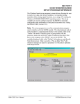
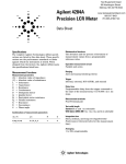
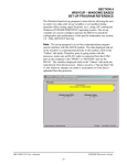
1
SECTION 4
HSMLT WINDOWS BASED
SET-UP PROGRAM REFERENCE
The Windows based set-up program is menu driven, allowing the user
to easily view data, alter set-up variables or set machine timing
(machine offset, timing signal locations, etc.), using a PC running the
Windows (95/98/ME/2000/XP/NT) operating system. The set-up
variables are used to configure and tune the M4503 to match the
configuration and performance of the specific tester (see Set-up
Reference, section 2.10).
Note: The set-up program is an on-line communications program
used to interface with the M4503 module. The data displayed and set
in the windows is communicated directly to the module, while in the
“Online” edit mode. Therefore, prior to going online with the
processor, make sure an RS-232 cable is connected from the COM
port on the computer to the "PROG" port on the M4503. The
variables displayed while in the “Online” edit mode are read directly
from the processor. Data is saved to a “Set-up Data” file (*.sdt)
whenever changes are made to a parameter or if the data is uploaded
from the processor.
HSL-LTA/LTS User’s Manual
SYSTEMS Electronics Group
- 39 -
SECTION 4
HSMLT WINDOWS BASED
SET-UP PROGRAM REFERENCE
________________________________________________________
4.1 GENERAL DESCRIPTION
Title Bar: At the top of the window is the “Title Bar”. The title bar
is used to display the name of the working “Set-up Data” file, as well
as, the name of the active “Window”. The title bar is dark if the
window is active and grayed if another window is active. The color
depends on the settings of the Display Properties of the Control Panel.
Status Bar: At the bottom of the window is the “Status Bar”. The
status bar is used to display system messages, online or offline mode,
as well as, the current time and date as set by the operating system.
The system messages panel displays general information about
operation of the system. The Online/Offline mode panel displays the
status of the current set-up program mode of operation. The mode of
operation can be changed by simply double clicking the online/offline
mode panel.
Hot Keys: Hot keys are activated by holding down the “ALT” key
and simultaneously pressing the underlined letter of the desired
function. Almost every function can be activated by either pressing a
series of hot keys or using the “TAB” key to move between fields.
Online/Offline Modes: The set-up program allows the user to
make changes while “Online” with the processor. The “Offline”
mode is used to preset parameters prior to download. All functions
are available to the user while “Online”, however, specific “Online”
functions are disabled in the “Offline” edit mode.
Note: Offline changes can only be made by enabling “Offline
Editing”, accessed under the “Edit” menu.
HSL-LTA/LTS User’s Manual
SYSTEMS Electronics Group
- 40 -
SECTION 4
HSMLT WINDOWS BASED
SET-UP PROGRAM REFERENCE
Getting Help: The entire contents of the user’s manual is contained
within the help file. Pressing Ctrl+H will display the help file
window.
Pressing the F1 key will display the contents file.
HSL-LTA/LTS User’s Manual
SYSTEMS Electronics Group
- 41 -
SECTION 4
HSMLT WINDOWS BASED
SET-UP PROGRAM REFERENCE
Hot spots allow jumps to other topics to display additional
information as desired.
Selecting About RTFCD7 from the Help menu will display a dialog
box listing information about the current revision of the setup
program and how to obtain technical support.
HSL-LTA/LTS User’s Manual
SYSTEMS Electronics Group
- 42 -
SECTION 4
HSMLT WINDOWS BASED
SET-UP PROGRAM REFERENCE
________________________________________________________
4.2 THE FILE MENU
The “File” menu allows the user to perform the following functions:
•
•
•
•
•
•
•
•
•
Create a “New” set-up “Data File”.
Open an existing “Data File”.
Save any changes made to the current “Data File” to disk.
Export Shift Data to a Text File.
Upload (save) Data from the Processor.
Download a SYSdev (.sdv) program to the processor
Download (restore) Data from the current set-up “Data File” to
the processor
Print a Report of the current set-up parameters.
Exit the set-up program
HSL-LTA/LTS User’s Manual
SYSTEMS Electronics Group
- 43 -
SECTION 4
HSMLT WINDOWS BASED
SET-UP PROGRAM REFERENCE
________________________________________________________
4.2.1 THE SET-UP DATA FILE
The set-up “Data File” (.sdt) is a binary access file, designed for fast
file I/O operation. When the set-up program is first invoked, the
default set-up parameters are loaded into memory. If changes are
made to any of the set-up parameters (either online or offline), as well
as shift data, the user will be flagged to “Save Changes” upon exit of
the program.
Note: Any windows based “Set-up” program can open a set-up
“Data File”, however, the data tables will not be properly aligned.
The user will be alerted to the problem if the set-up data file was
created by a different set-up program or a different revision of the
software.
The set-up “Data File” is similar to that of a word processing file.
When the program first starts a default file is loaded and the user is
able to make any changes as desired. The set-up program is unaware
of the settings and parameters that exist within the M4503.
Therefore, to normalize the set-up program with the processor, the
user should define or open an existing file, then upload “All”
variables from the processor. This allows the user to either create a
backup of the data or maintain an existing file. The user can even
open a data file for another tester, save the file to a new name, make
the necessary changes and simply download the new parameters to
another processor.
The following functions can be accessed any time, from any set-up or
display windows.
New: To create a “New” data file, select “New” from the “File”
menu or press “Ctrl + N”. This creates a completely new file, loaded
with the default variables and the word “[unnamed]” is displayed in
the title bar. If any changes were made to the existing file, the user is
prompted to save changes to the existing file.
Open: To “Open” and existing data file, select “Open” from the
“File” menu or press “Ctrl + O”. This displays a dialog box allowing
the user to select an existing data file to open. The name of the file
will be displayed in the title bar. If any changes were made to the
existing file, the user will be prompted to save any changes before
terminating the program.
HSL-LTA/LTS User’s Manual
SYSTEMS Electronics Group
- 44 -
SECTION 4
HSMLT WINDOWS BASED
SET-UP PROGRAM REFERENCE
Save: To “Save” data file to disk, select “Save” from the “File”
menu or press “Ctrl + S”. This displays a dialog box allowing the
user to select a folder and enter a name for the file. The user will be
notified if the file already exists and the extension “.sdt” will
automatically be added to the file name. If this is a “New” file, the
user will be prompted to enter a file name.
Save As: To save the data file to a new name, select “Save As”
from the “File” menu.. This displays a dialog box allowing the user
to select a folder and enter in a new name for the file. The user will
be notified if the file exists and the extension “.sdt” will automatically
be added to the file name.
Export Shift Data…: This function allows the user to export the
shift data to a “Tab Delimited” text file. This allows the user to easily
use the shift data to produce production reports.
________________________________________________________
4.2.2 UPLOAD (SAVE) DATA
The “Set-up” program allows the user to upload set-up parameters,
timing set-points and shift data from the M4503 into a set-up “Data
File”. This function is accessed from the “File” menu.
HSL-LTA/LTS User’s Manual
SYSTEMS Electronics Group
- 45 -
SECTION 4
HSMLT WINDOWS BASED
SET-UP PROGRAM REFERENCE
________________________________________________________
4.2.3 DOWNLOAD PROGRAM
The “Set-up” program allows the user to “Download” any SYSdev
program file to the M4503.
Note: To “Download” a SYSdev program to the processor, the
program must be “Online”. If “Online” mode cannot be achieved,
program download will not be executed. If the program is currently
“Offline”, the user will be prompted to first go “Online”.
Once selected, and the set-up program “Online” with the processor, a
dialog box will be displayed, allowing the user to select the SYSdev
file to download.
Note: Only the files with the “.sdv” file extension will be displayed.
It is important to keep in mind that only a valid M4500 PLC SYSdev
file can be downloaded through the set-up program. Care should be
taken when selecting a program to download.
HSL-LTA/LTS User’s Manual
SYSTEMS Electronics Group
- 46 -
SECTION 4
HSMLT WINDOWS BASED
SET-UP PROGRAM REFERENCE
Once selected, a message box is displayed informing the user of the
current program, revision and checksum of the program loaded in the
processor, as well as, that of the selected program. The user must
confirm their selection by clicking the “Yes” command button.
After the user confirms their choice, program download is initiated
and the current program download address is displayed. When
program download is complete, the user is prompted to acknowledge.
Control is passed back to the main program and the set-up program
remains in an “Online” edit mode.
HSL-LTA/LTS User’s Manual
SYSTEMS Electronics Group
- 47 -
SECTION 4
HSMLT WINDOWS BASED
SET-UP PROGRAM REFERENCE
________________________________________________________
4.2.4 DOWNLOAD (RESTORE) DATA
The set-up program allows the user to download “Set-up”
parameters, timing set-points and shift data to the M4503 from the
set-up “Data File”. This function is accessed from the “File” menu.
Note: Only the values contained within the current data file are used.
If the validity of the current data file is questionable, review the data
in an “Offline” mode prior to download.
________________________________________________________
4.2.5 PRINT REPORT
The “Set-up” program allows the user to generate a “Report” printout
of all the set-up parameters, timing set-points and shift data. This
function is accessed from the “File” menu.
At the top of each page, the report displays the name of the set-up file
being printed. At the bottom of each page is the date and time the
document was printed, as well as, the page number.
HSL-LTA/LTS User’s Manual
SYSTEMS Electronics Group
- 48 -
SECTION 4
HSMLT WINDOWS BASED
SET-UP PROGRAM REFERENCE
To printout a report of the settings contained in the set-up “Data File”,
perform the following:
1) From the “File” menu, select “Print Report” or press “Ctrl + P”.
This displays the “Print Setup” dialog box, allowing the user to
select a printer, as well as, the paper size and orientation. Once
the user selects “OK”, the report is generated and sent to the
specified printer device. This function makes use of the windows
print manager, which allows the user to continue with their work
while the document is being printed.
________________________________________________________
4.3 THE EDIT MENU
The “Edit” menu allows the user to perform the following functions:
•
•
•
Enable/Disable Offline Editing.
Set-up the Comm Port.
Set-Up Passcode
HSL-LTA/LTS User’s Manual
SYSTEMS Electronics Group
- 49 -
SECTION 4
HSMLT WINDOWS BASED
SET-UP PROGRAM REFERENCE
________________________________________________________
4.3.1 ENABLE OFFLINE EDITING
This function allows the user to perform “Offline” editing on the
currently loaded set-up data file. This allows the user the ability to
make any necessary changes to the set-up parameters while not online
with the processor.
If offline editing is not enabled, the user is only able to view the setup parameters and shift data. When the program is first invoked, the
default setting is offline editing disabled. The user will need to
specifically select “Enable Offline Editing” from the edit menu (or
press function key F2) to enable/disable this feature.
________________________________________________________
4.3.2 SETUP COMM PORT
This function allows the user to specify the serial communications
port and rate to talk to the M4503. The programming port of the
M4503 is set to 9600 baud.
Once selected, a dialog box requesting the user to select a “Comm
Port” and “Baud Rate” will be displayed. The default setting is
COM1 at 9600 baud. The option to select the 19200 baud rate is to
allow the user to communicate with the processor via the S4516 serial
communications board.
In most cases the user will only need to specify the communications
port and leave the baud rate at 9600. If communication problems
occur, make sure there is a secure connection from the PC to the PLC.
Then check the Comm port. In most cases the user will only need to
select a new Comm port. If communication problems persist there
may be another program causing a conflict with the port. Check the
port configuration from the “Settings” folder.
HSL-LTA/LTS User’s Manual
SYSTEMS Electronics Group
- 50 -
SECTION 4
HSMLT WINDOWS BASED
SET-UP PROGRAM REFERENCE
________________________________________________________
4.3.3 EDIT SETUP PASSCODE
The edit “Set-up Passcode” is an “Online” function only. This allows
the user the ability to directly change the value of the Keypad/Display
“Set-up Passcode”.
Once selected, an input box is displayed, allowing the user to view
the current “Passcode” setting and to change the value if necessary.
If the passcode is set to zero, passcode entry is disabled. The operator
can press the Set-up key on the Keypad/Display and simply press the
<ENTER> key to gain access to the set-up parameters without having
to enter a zero.
If the value of the “Set-up Passcode” is set somewhere between 1 and
65,000, “Passcode Entry” is enabled. This requires the operator to
enter in the “Correct” passcode to gain access to the set-up
parameters.
Note: Passcode entry is only in effect when the “Set-up Enable”
input is off.
If an invalid value is entered, the passcode value will not be reset and
a message box notifying the user of the error is displayed.
HSL-LTA/LTS User’s Manual
SYSTEMS Electronics Group
- 51 -
SECTION 4
HSMLT WINDOWS BASED
SET-UP PROGRAM REFERENCE
________________________________________________________
4.4 THE VIEW MENU
The “View” menu allows the user to perform the following functions:
•
•
•
View the “Target Board Interface”
View “Online” Data
View “Offline” Data
HSL-LTA/LTS User’s Manual
SYSTEMS Electronics Group
- 52 -
SECTION 4
HSMLT WINDOWS BASED
SET-UP PROGRAM REFERENCE
________________________________________________________
4.4.1 TARGET BOARD INTERFACE
This function allows the user to view fault codes, S3000 network
communication error codes and review the current “Ident” and
“Revision” of the application program. This is accessed from the
“View” menu, by selecting “Target Board Interface”.
Once invoked, the set-up program will prompt the user to select a
program to compare with the one existing in the processor. Whether
a program is selected or the user cancels, the setup program will
attempt to communicate with the M4503. If unsuccessful a warning
message will be displayed, prompting the user to either “Retry” or
“Cancel” the operation. If the operation is canceled and
communication with the processor cannot be established the system
will be placed in an “Offline” mode, however the “Target Board
Interface” window will be displayed.
HSL-LTA/LTS User’s Manual
SYSTEMS Electronics Group
- 53 -
SECTION 4
HSMLT WINDOWS BASED
SET-UP PROGRAM REFERENCE
________________________________________________________
4.4.2 VIEW ONLINE DATA
This function allows the user to place the set-up program in an
“Online” mode with the processor. This is accessed from the “View”
menu, by selecting “Online Data” or by simply pressing the “F3”
function key.
Note: The program can be toggled between “Offline” and “Online”
by simply double clicking on the “Online” or “Offline” panel
displayed in the status bar at the bottom of the window.
Once invoked, the set-up program will attempt to open the Comm
port and communicate with the M4503. If the set-up program is
unsuccessful, a warning message will be displayed prompting the user
to either “Retry” or “Cancel” the operation. If the operation is
canceled and communication with the processor cannot be established
the system will be placed in an “Offline” edit mode.
Note: Anytime while the set-up program is “Online” with the
processor and communication is interrupted, a warning message will
be displayed, prompting the user to either “Retry” or “Cancel” the
operation.
________________________________________________________
4.4.3 VIEW OFFLINE DATA
This function allows the user to place the set-up program in an
“Offline” mode. This is accessed by the “View” menu, by selecting
“Offline Data” or by simply pressing the “F4” function key. This
allows the user to perform “Offline” editing. All values displayed in
“Offline” edit mode reflect the actual values contained in the
currently loaded set-up data file.
Note: The program can be toggled between “Online” and “Offline”
by simply double clicking on the “Online” or “Offline” panel
displayed in the status bar at the bottom of the window.
Once invoked, the set-up program will close the Comm port and cease
communication with the M4503.
HSL-LTA/LTS User’s Manual
SYSTEMS Electronics Group
- 54 -
SECTION 4
HSMLT WINDOWS BASED
SET-UP PROGRAM REFERENCE
________________________________________________________
4.5 THE WINDOW MENU
The “Window” menu allows the user to select one of five different
Display/Set-up windows to modify set-up parameters, view shift data
or receive feedback about the current status of the control system.
Once a window menu item is selected, a check mark is placed next to
the selected item and the selected window is displayed and the name is
changed in the title bar of the main window.
Note: “Read” only variables are displayed in blue with a gray
background. Any variables that can be altered by the user are
displayed in black with a white background. In most cases, a
parameter that can be changed by the user will have associated with it
increment and decrement controls. The user can either click on the
desired parameter to adjust and enter in a new value, or use the
increment or decrement controls to change the value by 1 unit.
HSL-LTA/LTS User’s Manual
SYSTEMS Electronics Group
- 55 -
SECTION 4
HSMLT WINDOWS BASED
SET-UP PROGRAM REFERENCE
________________________________________________________
4.5.1 THE MAIN DISPLAY WINDOW
The “Main Display” window is used to display the general state of the
control system. This window is selected from the “Window” menu.
The following is a list of the functions of the “Main Display”
window.
Messages: The “Messages” display is continuously updated. It
displays alarm and status messages specific to the M4503, as well as,
the current “Online” or “Offline” status of the set-up program. By
simply scrolling the display, the user is able to view all active alarm
and status messages. If no alarm or status messages are active, a
default message is displayed.
Machine CPM: This display is only active while “Online” and
displays the current speed of the machine in “Cans Per Minute”.
Good Cans: This is the total number of good cans tested so far into
the shift. This is essentially a can counter.
Leaker Rejects: This is the total number of leaker cans rejected by
the machine so far into the shift.
HSL-LTA/LTS User’s Manual
SYSTEMS Electronics Group
- 56 -
SECTION 4
HSMLT WINDOWS BASED
SET-UP PROGRAM REFERENCE
Vision Rejects: This is the total number of cans rejected by the
vision inspection system (if used).
%Scrap (total): This is the total percentage of cans tested that were
blown off either due to a vision or leaker reject
%Scrap (leaker): This is the total percentage of cans tested that
were blown off due to a leaker reject signal.
%Scrap (vision): This is the total percentage of cans tested that
were blown off due to a vision reject signal.
Note: If a can is both a vision reject and a leaker reject, it will only
be counted as a leaker reject and not as both.
________________________________________________________
4.5.2 THE SET-UP PARAMETERS WINDOW
The “Set-up Parameters” window is used to view and adjust any of
the set-up parameters. This window is selected from the “Window”
menu.
This window utilizes a “TAB” control to divide the set-up parameters
into three categories, similar to that of the Keypad/Display.
HSL-LTA/LTS User’s Manual
SYSTEMS Electronics Group
- 57 -
SECTION 4
HSMLT WINDOWS BASED
SET-UP PROGRAM REFERENCE
Reject Shift Registers:
1) Can Presence Shifts (0-44): This is the number of pockets
from the Can Presence Sensor to the tester discharge (pocket
where cans are released from the machine).
2) Leaker Reject Shifts (0-44): This is the number of pockets
from the Reject Array Receiver pocket to the tester discharge
(pocket where cans are released from the machine).
3) Vision Reject Shifts (0-44): This is the number of pockets
from the vision inspection system reject pocket to the tester
discharge (pocket where cans are released from the machine).
4) Pocket #1 Offset (0-Number of Pockets): This number is
used to compensate for the number of pockets between the Reject
Receiver and discharge location on the tester. This is adjusted
such that a reject from pocket #1 is counted as a reject from
pocket #1 in the “Rejects per Pocket” screen. This number is
approximately = “Total Number of Pockets” – “Leaker Reject
Shift” plus or minus one pocket.
5) Rejected Pocket: This is the number of the last pocket that
generated a vision reject. This is only available in the online
mode.
6) Array Fault Offset (0-Number of Pockets): This number is
used to properly display a faulted array head when a Leak
Detection Array Fault alarm occurs.
7) Faulted Array Head: This displays the faulted array head when
a Leak Detection Array Fault alarm occurs.
HSL-LTA/LTS User’s Manual
SYSTEMS Electronics Group
- 58 -
SECTION 4
HSMLT WINDOWS BASED
SET-UP PROGRAM REFERENCE
Blow-off Parameters:
1) Can Neck Size (in 0.01 inches): This parameter is used to
calculate when to activate the reject blow-off as a function of the
can speed. The can neck size is simply the diameter of the neck at
it's most narrow point in 0.01 inches. For example, if the neck
measures 2.15" at it's most narrow point, simply enter 215 for the
can neck size. The valid range of this value is 180 to 350.
The “Can Neck Size” parameter can be used to compensate for the
response time of the blow-off solenoids. To advance the blow-off
(activate solenoids earlier), make the “Can Neck Size” larger. To
retard the blow-off (activate the solenoids later), make the “Can
Neck Size” smaller.
2) Reject Solenoid Pulse Time (msec): This is the number of
milliseconds that the reject solenoids will be pulsed for when a
bad can is rejected. This is adjusted to get a strong pulse of air to
reject the can. Too short of time will result in the can not being
fully rejected (jamming). Too long of time will disturb the
following can at high speeds also causing jamming. Typically this
is set from 10 to 12msec. The valid range for this parameter is 8 to
50msec.
HSL-LTA/LTS User’s Manual
SYSTEMS Electronics Group
- 59 -
SECTION 4
HSMLT WINDOWS BASED
SET-UP PROGRAM REFERENCE
3) Diverter Solenoid Pulse Time (.01sec): This is the amount
of time (in .01seconds) the “Leaker/Vision” diverter solenoid (if
used) is pulsed to divert a “Leaker Reject” into a separate reject
chute. The valid range for this parameter is 0 to 250 (2.5seconds).
4) Can Time (msec): This is the amount of time in milliseconds
that the reject photo eye sees a can.
5) Blow-off Solenoid “ON” Time (msec): The blow-off
solenoid “ON” time is the amount of time in milliseconds that the
blow-off solenoid will be activated to blow-off a can
6) Blow-off Solenoid Delay Time (msec): Based on the can
neck size and the can time, the control system calculates a “Delay
Time” based on the speed of the can.
Note: Adjusting the can neck size will affect the blow-off
solenoid delay time.
7) Bad Can Blow-off - Test Blow-off Solenoid: This button is
used to test the reject blow-off solenoid both while the machine is
running with cans or while the machine stopped. After making
adjustments to the can neck size, use this function to test the reject
blow-off solenoid.
HSL-LTA/LTS User’s Manual
SYSTEMS Electronics Group
- 60 -
SECTION 4
HSMLT WINDOWS BASED
SET-UP PROGRAM REFERENCE
Machine Timing:
1) Sync Timing (CH00): The Sync Timing is used to clock in the
reject data from the Reject Array Receiver, Array Fault Receiver,
and the vision system reject signal as well as clock the data from
the Can Presence sensor. The Sync Timing should be as far as
possible from the occurrence of the Can Presence sensor, Reject
Receiver, Array Fault Receiver and the Vision Reject input signal.
2) Pocket #1 Timing (CH01): The Pocket #1 Timing is used to
reset the pocket count to pocket #1. Set the Pocket #1 Timing 90
degrees following the Sync Timing.
3) Discharge Timing (CH02): The Discharge Timing (CH02)
should be set about 30 degrees before the location that the can is
released from the tester. With cans in the machine, rotate the
tester by hand to the location where the can is just released. Set
the Discharge Timing (CH02) to the position 30 degrees before
this can release position.
4) PLC Timing (CH03): The PLC Timing is provided as an extra
timing signal, which can be used by the existing host control
system. Set this timing as desired.
HSL-LTA/LTS User’s Manual
SYSTEMS Electronics Group
- 61 -
SECTION 4
HSMLT WINDOWS BASED
SET-UP PROGRAM REFERENCE
5) Machine Position: This displays the position of the resolver,
pocket to pocket (360 degrees per pocket).
6) Absolute Position: This displays the absolute position of the
resolver in counts for one full revolution of the discharge starwheel.
7) Zero Resolver: Position the machine at machine zero. This is
the location where the pocket #1 reject reset photo detector is
perfectly aligned with the reset lamp (see Machine Zero2.10.3).
Auto zero the resolver by clicking the “ZERO MACHINE"
button. The position of the machine will now be displayed at zero
Note: The “Zero Resolver” button is only active in the online
mode while the machine is at zero speed (no motion detected).
HSL-LTA/LTS User’s Manual
SYSTEMS Electronics Group
- 62 -
SECTION 4
HSMLT WINDOWS BASED
SET-UP PROGRAM REFERENCE
Calibrate FIFO:
This is used to calibrate the can tracking error detection logic, as well
as, observe the “Can Check Speed”, the instantaneous number of cans
in the FIFO, average number of cans in the FIFO, the min and max
error limits and the number of “Low” corrections, “High” corrections
and missed can presence counts.
Can tracking error detection logic is used to determine when a reject
FIFO error had occurred. This is generally due to the “Can Presence”
sensor missing a can (side wall damage on the can) or when the
“Reject Photo Eye” misses a can or double clocks a can (severe neck
damage).
The error detection logic verifies the reject FIFO is correct. This is
done by comparing the average number of cans in the FIFO to a
“calibrated” average.
The error detection logic is calibrated by running the machine at top
speed with a continuous flow of cans. By clicking on the “Calibrate
FIFO” button, the error detection logic is calculated based on the
speed of the machine.
Note: Clicking the “Calibrate FIFO” button when the machine is
stopped will disable the can tracking error detection logic.
HSL-LTA/LTS User’s Manual
SYSTEMS Electronics Group
- 63 -
SECTION 4
HSMLT WINDOWS BASED
SET-UP PROGRAM REFERENCE
To calibrate the FIFO error detection perform the following:
1) With the machine stopped, select “Calibrate FIFO” tab in the
“Set-up” window.
2) Click the “Calibrate FIFO” button. This disables the error
detection. The “Can Check Speed” is set at 4800 cpm and the
FIFO Min is set to 0.0 and the FIFO Max is set to 9.9.
3) With the FIFO error detection disabled, run the machine at top
speed with a continuous flow of cans.
Note: The machine must run for at least 10 seconds at top speed
to correctly calibrate the FIFO error detection.
4) Verify that the correct “Bad Can” is being blown off. This
verifies that the FIFO is correct when the calibration is performed.
5) Click the “Calibrate FIFO” button again. This enables the error
detection. The “Can Check Speed” is now set, as well as, the
FIFO Min and Max settings.
Note: FIFO error detection calibration can be performed
whenever the machine is running with a continuous flow of cans.
Calibrating the FIFO error detection also resets the fault counts.
Machine Speed (cpm): This is the current speed of the tester in
CPM.
Can Check Speed: This is calculated automatically when the
FIFO error calibration is performed and is set to approximately 80%
of the top speed of the machine. Whenever the speed of the tester is
at or above the can check speed, FIFO error detection is enabled.
Number of Cans in FIFO: This is the instantaneous number of
cans in the FIFO.
Number of Cans in FIFO - Max: This is calculated automatically
when the FIFO error calibration is performed. This number is set to
approximately 110% of the average number of cans in the FIFO when
the tester is running at top speed
Number of Cans in FIFO - Min: This is calculated automatically
when the FIFO error calibration is performed. This number is set to
approximately 90% of the average number of cans in the FIFO when
the tester is running at top speed.
HSL-LTA/LTS User’s Manual
SYSTEMS Electronics Group
- 64 -
SECTION 4
HSMLT WINDOWS BASED
SET-UP PROGRAM REFERENCE
Number of Cans in FIFO - Avg.: This is the average number of
cans in the FIFO when the machine is running above 800 cpm
FIFO Low Corrections Count: This is the number of FIFO faults
that have occurred when the average number of cans in the FIFO has
dropped below the FIFO Min. A FIFO low fault would be caused by
double clocking a can at the “Reject Photo Eye”. This count is
retained indefinitely but can be reset by clicking the “Calibrate FIFO”
button.
FIFO High Corrections Count: This is the number of FIFO faults
that have occurred when the average number of cans in the FIFO has
exceeded the MIFO Max. A FIFO high fault would be caused by
missing a can at the “Reject Photo Eye”. This count is retained
indefinitely but can be reset by clicking the “Calibrate FIFO” button.
Missed Can Presence Count: This is the number of FIFO faults
that have occurred due to missing a can at the “Can Presence” sensor.
This count is retained indefinitely but can be reset by clicking the
“Calibrate FIFO” button.
HSL-LTA/LTS User’s Manual
SYSTEMS Electronics Group
- 65 -
SECTION 4
HSMLT WINDOWS BASED
SET-UP PROGRAM REFERENCE
Critical Input Positions:
The “View Critical Input Positions” menu is used to view the
position, in degrees, that the Reject Receiver, Array Fault Receiver,
Can Presence Sensor, and Vision Reject signals are coming in at
while the machine is running. Primarily this is to verify that none of
these signals are coming in within +/-60 degrees of the “Sync” timing.
If any of them do, the system could potentially miss clock the FIFO
causing the wrong can to be intermittently rejected.
HSL-LTA/LTS User’s Manual
SYSTEMS Electronics Group
- 66 -
SECTION 4
HSMLT WINDOWS BASED
SET-UP PROGRAM REFERENCE
________________________________________________________
4.5.3 THE SERIAL COMMUNICATIONS WINDOW
The Serial Communications window is used to view the configuration
status of the S4516 serial communications board (if installed), as well
as, view the status of the Allen-Bradley DF1 communication protocol
and set-up the Allen-Bradley PLC communication parameters. From
this window the user can view or adjust the following parameters:
•
•
•
•
•
•
View the S4516 configuration status.
View the S4516-DF1 serial communication status.
View the Allen-Bradley Link Layer serial communication status.
Select the Allen-Bradley PLC type (PLC5 or SLC500) to
communicate to.
View/Set the Allen-Bradley PLC destination node.
Select the starting Allen-Bradley PLC destination file number.
HSL-LTA/LTS User’s Manual
SYSTEMS Electronics Group
- 67 -
SECTION 4
HSMLT WINDOWS BASED
SET-UP PROGRAM REFERENCE
1) S4516 Configuration Status: This displays the current state
of the configuration of the S4516 serial communications board.
System function sfunc19(); (S4516 configuration) is used to set
the S4516 configuration (network node address, network baud
rate and USER port baud rate). This must be executed prior to
executing ether system functions 10, 11 or 13. System function
19 is generally executed in the “Initialization” file of the user
program.
The following values are returned from a system function 19 call:
1 = Busy.
2 = Done (S4516 Successfully configured).
3 = Invalid Parameter (either network node address, network
baud rate or USER port baud rate is invalid).
4 = Timeout (no response form S4516)
32 = Hardware ACK error from S4516
34 = Invalid S4516 Slot Address (W8156 must be loaded with
the slot address of the S4516, prior to executing system
function 19).
2) Transmit Data Status: This represents the state of the data
packet transmission and will typically display either “Busy” or
“Done”. If there are problems delivering the message packet, the
response code, along with a description, will be displayed.
Note: The “Transmit Data Status (prev.)” is used to view the last
or previous status.
3) Current Transaction: This is the “Transaction” number
delivered to the Allen-Bradley PLC.
4) Active Command: This displays either “Read” or “Write”.
This is used to view the command type of the current transaction.
5) Number of BYTES Received: This displays the current
number of bytes received from either a “Command” or “Reply”
message packet.
6) Received Command BIT Status: This displays the state of
the command received. If this displays a “Reply”, then the
command was sent from the M4503. If this displays “Command”,
then a command action was received by the M4503.
HSL-LTA/LTS User’s Manual
SYSTEMS Electronics Group
- 68 -
SECTION 4
HSMLT WINDOWS BASED
SET-UP PROGRAM REFERENCE
7) A/B Link Layer Status: This displays the status of the receipt
of the message packet sent to the Allen-Bradley PLC. If the
delivery is not successful, an error code along with a description
is displayed. Refer the to the Allen-Bradley Communication
Protocol and Command Set reference manual for more
information on “Link Layer” error codes.
8) A/B Link Layer – Current Transaction Received: This is
the “Transaction” number received from the Allen-Bradley PLC.
9) PLC Type: This is used to specify the “Type” of PLC the
M4503 will communicate to. The user can choose from “PLC5”
or “SLC500”.
Note: This parameter should be set prior to communicating with
an A/B processor.
10) Destination Node: This is used to set the node number of the
A/B PLC to send and receive data from. This also displays the
node number of the A/B PLC that send a “Command” message
packet.
11) Destination File Number: This is the file number the M4503
will read and write data from. See Appendix B for a description
of the data read from and written to an Allen-Bradley PLC.
HSL-LTA/LTS User’s Manual
SYSTEMS Electronics Group
- 69 -
SECTION 4
HSMLT WINDOWS BASED
SET-UP PROGRAM REFERENCE
________________________________________________________
4.5.4 THE SHIFT DATA WINDOW
The “Shift Data” window is used to view the shift data collected by
the M4503. This window is selected from the “Window” menu.
This window utilizes a “TAB” control to divide the set-up parameters
into three categories, similar to that of the Keypad/Display. These
sections are as follows:
Rejects Per Pocket:
The number of leaker rejects per pocket menu is provided to aid in the
trouble-shooting of a light seal problem with a pocket or pockets. The
total number of rejects for each pocket since the last reset or end of
shift is displayed.
Note: Prior to selecting this selection, make sure the RS-232 cable is
connected from the COM port on the computer to the "PROG" port of
the M4503.
1) Rejected Pocket: This is the number of the last pocket that
generated a vision reject. This is only available in the online
mode.
HSL-LTA/LTS User’s Manual
SYSTEMS Electronics Group
- 70 -
SECTION 4
HSMLT WINDOWS BASED
SET-UP PROGRAM REFERENCE
2) Rejects Per Pocket #: This is the total number of leaker
rejects for each pocket. This data is displayed and updated
continuously in the respective field for each pocket. A
disproportionately high count for a particular pocket indicates a
light seal problem for that pocket.
3) Reset Rejects: This provides the operator the opportunity to
reset the counts for troubleshooting purposes. Resetting these
counts does not affect the total number of rejects per for the shift.
This function is only available in the online mode.
Current Shift:
This selection is used to view the Current Shift data. This data is the
totals so far into the shift. This data is transferred to the "Last shift"
data when the end of shift input transfers from a "0" to a "1". This can
be at the end of either an 8 or 12 hour shift or alternatively could be
done at label changes such that the data collected would be for label
runs rather than complete shifts.
Note: Prior to selecting this selection, make sure the RS-232 cable is
connected from the COM port on the computer to the PROG PORT
on the M4503. The following data is displayed in the "Current Shift
(Totals so far)" menu:
HSL-LTA/LTS User’s Manual
SYSTEMS Electronics Group
- 71 -
SECTION 4
HSMLT WINDOWS BASED
SET-UP PROGRAM REFERENCE
1) End of Shift - Transfer Data: This button is used to invoke an
end of shift data transfer. This will cause the current shift data to
be transferred to the last shift and then all counts reset to zero.
2) Total Good Cans Tested: This is the total number of good
cans tested so far into the shift. This is essentially a can counter.
3) Total Leaker Rejects: This is the total number of leaker cans
rejected by the machine so far into the shift.
4) Total Vision Inspection Rejects: This is the total number of
cans rejected by the vision inspection system (if used).
5) %Scrap (total): This is the total percentage of cans tested that
were blown off either due to a vision or leaker reject
6) %Scrap (leaker): This is the total percentage of cans tested that
were blown off due to a leaker reject signal.
7) %Scrap (vision): This is the total percentage of cans tested that
were blown off due to a vision reject signal.
Note: If a can is both a vision reject and a leaker reject, it will
only be counted as a leaker reject and not as both.
8) Rejects Per Pocket: This is the total leaker rejects for each
pocket. A disproportionately high count for a particular pocket
indicates a light seal problem for that pocket.
HSL-LTA/LTS User’s Manual
SYSTEMS Electronics Group
- 72 -
SECTION 4
HSMLT WINDOWS BASED
SET-UP PROGRAM REFERENCE
Last Shift:
The "Last Shift" data is identical to the current shift data except it is
the totals for the previous 8 or 12 hour shift or previous label run,
how ever the shift collection is set-up. This allows data collection and
diagnostics to take place automatically over a two shift period. Refer
to the previous section for definitions of the data fields in the "Last
Shift" data menu.
HSL-LTA/LTS User’s Manual
SYSTEMS Electronics Group
- 73 -
SECTION 4
HSMLT WINDOWS BASED
SET-UP PROGRAM REFERENCE
________________________________________________________
4.5.5 THE I/O STATES WINDOW
The “I/O States” window is provided to display states of the inputs
and outputs. The control boards, the states of the timing channels, as
well as states of the M4503 are shown. This includes the interrupt
inputs (IN0 and IN1), the analog I/O and the resolver. These values
are displayed as read by the M4503 processor
HSL-LTA/LTS User’s Manual
SYSTEMS Electronics Group
- 74 -