1
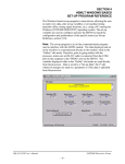
SECTION 2
INSTALLATION
________________________________________________________
2.7 HSM-DUCTOR SET-UP
The HSM-DUCTOR is shipped from the factory with the
“HSMDCTR” application program loaded into the M4503 module.
This is a standard program used to implement the HSM-DUCTOR
pneumatic ductor algorithms.
Once the HSM-DUCTOR is installed and the control system is
powered up, perform the following.
1) Modify the existing host PLC program such that the PLC output
connected to B100.2 (Ductors Auto ON) is “ON” whenever cans
are feeding into the decorator.
2) Set the desired Maximum Cycle Duration. The Maximum Cycle
Duration is set to 1/10th of a can resolution. The range of this
parameter is from 140 to 650 and defines the upper limit or the
longest amount of time between ductor cycles. Care should be
taken not to set this parameter too low, as this would restrict the
operators range of adjustment. The “Cycle” duration is set
individually for each ink station and is the rate at which ink is
transferred from the fountain roll.
3) Set the desired Maximum "On" Duration. The maximum “On”
duration is set to 1/10th of a can resolution. The range of this
parameter is from 0 to 200 and defines the upper limit or the
longest amount of time the ductor roll can be in contact with the
fountain roll. The “On” duration is set individually for each ink
station and is the amount of time the ductor roll is in contact with
the fountain roll.
4) Set the Response Time Compensation. The response time
compensation parameters is used to adjust the “On” duration
based on the difference between the “ON” and “off” response
time of the ductor solenoid. As and example, if the “ON”
response time were 40 msec. and the “off” response time was 15
msec., then this parameter would need to be set to 25 msec.
The “ON” response time is defined as the time ductor is activated
to the time it comes in contact with the fountain roll. The “off”
response time is the time the ductor is deactivated to the time it
lifts off of the fountain roll. If the optional feedback sensors are
to be used, this parameter should be set to zero.
HSM-DUCTOR User’s Manual
SYSTEMS Electronics Group
- 13 -
SECTION 2
INSTALLATION
5) Set the Color Gain parameter. This parameter allows the color
density to be increased proportionately up or down as a function
of machine speed. The valid range of this parameter is 50% to
150% per 2000 CPM. When set to 100%, no increase or decrease,
as a function of speed will occur. When set to 50%, the color
density will drop 50% from 0 to 2000CPM. When set to 150%
the color density will increase by 50% from 0 to 2000CPM. This
parameter is used to compensate for ink atomization (misting) as a
function of speed (higher speed = proportionately higher ink
misting).
6) If the ductor feedback sensors are to be used, enable the particular
stations that have feedback. If the ductor feedback is not used,
disable all stations. This parameter enables the individual
feedback faults and should only be enabled when the optional
feedback sensors are used. Once enabled, the M4503 will verify
that the ductor is cycling properly. If a ductor is not detected as
cycling properly, the “Ductor Feedback Fault” is energized,
indicating a problem with the ductor cycling control.
If a “Ductor Feedback Fault” does occur, the ductors should be
manually activated to verify proper cycling operation, as well as,
the sensor for proper feedback operation. The feedback sensor
should be set such that it is only “ON” when the ductor is in
contact with the fountain roll.
7) Enable “Set Passcode” and select “Color Control” to enter a new
passcode. If “Set-Up” is enabled the user will not be prompted to
enter a new passcode. Factory default is set to zero.
8) Once set-up is complete, upload this data to disk using the “Setup” program software. This allows the data to be downloaded to
the module again if the module is replaced. This data should be
backed up on a periodic basis as labels are added or changed.
HSM-DUCTOR User’s Manual
SYSTEMS Electronics Group
- 14 -