1
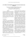
Freescale Semiconductor
Simple Real-time Sonar
with the DSP56824
Application Note
by
Mihai V. Micea, Lucian Muntean, and Daniel Brosteanu
AN2086/D
Rev. 0, 06/2001
How to Reach Us:
Home Page:
www.freescale.com
E-mail:
[email protected]
USA/Europe or Locations Not Listed:
Freescale Semiconductor
Technical Information Center, CH370
1300 N. Alma School Road
Chandler, Arizona 85224
+1-800-521-6274 or +1-480-768-2130
[email protected]
Europe, Middle East, and Africa:
Freescale Halbleiter Deutschland GmbH
Technical Information Center
Schatzbogen 7
81829 Muenchen, Germany
+44 1296 380 456 (English)
+46 8 52200080 (English)
+49 89 92103 559 (German)
+33 1 69 35 48 48 (French)
[email protected]
Japan:
Freescale Semiconductor Japan Ltd.
Headquarters
Information in this document is provided solely to enable system and software
ARCO Tower 15F
implementers to use Freescale Semiconductor products. There are no express or
1-8-1, Shimo-Meguro, Meguro-ku,
Motorola reserves the right to make changes without further
notice
to any
products
Motorola
no any
warranty,
implied
copyright
licenses
grantedherein.
hereunder
to design makes
or fabricate
integrated
Tokyo
153-0064
representation or guarantee regarding the suitability of its products
fororany
particular
purpose,
northe
does
Motorola
assume
any liability
circuits
integrated
circuits
based on
information
in this
document.
Japan
arising out of the application or use of any product or circuit, and
specifically
disclaimsreserves
any andthe
allright
liability,
including
without
Freescale
Semiconductor
to make
changes
withoutlimitation
further notice to
0120
191014 oror+81
3 5437damages.
9125
consequential
incidental
“Typical” parameters which
be provided
in Motorola
data sheets
and/or
specifications
can or
any may
products
herein. Freescale
Semiconductor
makes
no warranty,
representation
and do vary in different applications and actual performance may
vary over
time. the
All operating
including
“Typicals”
must
guarantee
regarding
suitability ofparameters,
its products for
any particular
purpose,
nor does
[email protected]
be validated for each customer application by customer’s technical
experts.
Motorolaassume
does not
any license
under
its patent
Freescale
Semiconductor
anyconvey
liability arising
out of the
application
or use of
rights nor the rights of others. Motorola products are not designed,
intended,
authorized
use as
systems
any product
or circuit,or
and
specifically for
disclaims
anycomponents
and all liability,inincluding
without
Asia/Pacific:
intended for
surgical implant
into
the Ltd.
body, or other applications
intended
to support
life, or for
any other
application
in which
the be
limitation
consequential
or incidental
damages.
“Typical”
parameters
which may
Freescale
Semiconductor
Hong
Kong
failure of the Motorola product could create a situation whereprovided
personal
injury or Semiconductor
death may occur.
Shouldand/or
Buyer
purchase can
or use
in Freescale
data sheets
specifications
and do
Technical
Information
Motorola products
for Center
any such unintended or unauthorized application,
Buyer
shall indemnify
hold Motorola
officers,
vary in different
applications
and actual and
performance
may varyand
overits
time.
All operating
2employees,
Dai King Street
subsidiaries, affiliates, and distributors harmless parameters,
against all including
claims, “Typicals”
costs, damages,
and expenses,
and reasonable
must be validated
for each customer
application by
Tai
Po Industrial
Estateout of, directly or indirectly, any claimcustomer’s
attorney
fees arising
of personal
injury
or death
associated
with such
unintended
technical
experts.
Freescale
Semiconductor
does not
convey anyor
license
unauthorized
use, even
negligent
regarding
the
manufacture
the part.
its patent
rights nor
thedesign
rights oforothers.
FreescaleofSemiconductor
products are
Tai
Po, N.T., Hong
Kongif such claim alleges that Motorola wasunder
not designed, intended, or authorized for use as components in systems intended for
+800 2666 8080
Motorola, Inc. is an Equal Opportunity/Affirmative Action Employer.
surgical implant into the body, or other applications intended to support or sustain life,
[email protected]
or for any other application in which the failure of the Freescale Semiconductor product
Motorola and the Stylized
Logo are registered trademarkscould
of Motorola,
Inc. Reg.
U.S.
Pat. &injury
Tm. or
Off.
create a situation
where
personal
death may occur. Should Buyer
For Literature Requests Only:
purchase or use Freescale Semiconductor products for any such unintended or
Freescale Semiconductor Literature Distribution Center
unauthorized application, Buyer shall indemnify and hold Freescale Semiconductor
P.O. Box 5405
and its officers, employees, subsidiaries, affiliates, and distributors harmless against all
How
to reach us:
claims, costs, damages, and expenses, and reasonable attorney fees arising out of,
Denver, Colorado 80217
directly or indirectly, any claim of personal injury or death associated with such
1-800-441-2447
or
303-675-2140
USA/EUROPE/Locations Not Listed: Motorola Literature
Distribution;
P.O. Box
Denver,
Colorado,
80217.
unintended
or unauthorized
use, 5405,
even if such
claim alleges
that Freescale
Fax:
303-675-2150
1–303–675–2140 or 1–800–441–2447
Semiconductor was negligent regarding the design or manufacture of the part.
[email protected]
JAPAN: Motorola Japan Ltd.; SPS, Technical Information Center, 3–20–1, Minami–Azabu, Minato–ku,
Tokyo 106–8573 Japan. 81–3–3440–3569
ASIA/PACIFIC: Motorola Semiconductors H.K. Ltd., Silicon Harbour Centre, 2 Dai King Street,
Tai Po Industrial Estate, Tai Po, N.T., Hong Kong. 852–26668334
Technical Information Center: 1–800–521–6274
HOME PAGE: http://www.motorola.com/semiconductors/
© Copyright Motorola, Inc., 2001
Abstract and Contents
The focus of this paper is on the techniques of analysis and implementation of a simple real-time SONAR
system with a DSP56824-based board connected to a host computer.
SONAR system’s general architecture and its principles of functioning are further presented. Specific
digital signal processing algorithms developed for the ultrasound frequencies are described in detail, along
with their implementation using the DSP56824 processor.
Finally, a particular application developed with the proposed SONAR system is presented as a case study.
Some prospects and future work related to this subject are also mentioned as conclusion.
1
Introduction . . . . . . . . . . . . . . . . . . . . . . . . . . . . . . . . . . . . . . . . . . . . . . . . . . . . . . . . . . 1
1.1
General Description of a Sonar System . . . . . . . . . . . . . . . . . . . . . . . . . . . . . . . . . . . . . . . 1
2
Proposed Sonar System Description . . . . . . . . . . . . . . . . . . . . . . . . . . . . . . . . . . . 3
2.1
2.2
2.3
General System Architecture . . . . . . . . . . . . . . . . . . . . . . . . . . . . . . . . . . . . . . . . . . . . . . . 3
Transducer Interface Circuits . . . . . . . . . . . . . . . . . . . . . . . . . . . . . . . . . . . . . . . . . . . . . . . 5
Stepper Motor Control . . . . . . . . . . . . . . . . . . . . . . . . . . . . . . . . . . . . . . . . . . . . . . . . . . . . 6
3
Sonar Implementation on the DSP56824 . . . . . . . . . . . . . . . . . . . . . . . . . . . . . . . . 7
3.1
3.2
3.3
3.4
3.5
3.6
Definition and Initialization Phase . . . . . . . . . . . . . . . . . . . . . . . . . . . . . . . . . . . . . . . . . . . 7
Emitted Wave Generation. . . . . . . . . . . . . . . . . . . . . . . . . . . . . . . . . . . . . . . . . . . . . . . . . 11
Echo Signal Sampling and Storing . . . . . . . . . . . . . . . . . . . . . . . . . . . . . . . . . . . . . . . . . . 11
Target Polar Coordinates Calculation. . . . . . . . . . . . . . . . . . . . . . . . . . . . . . . . . . . . . . . . 12
Transmission of Results to the Host . . . . . . . . . . . . . . . . . . . . . . . . . . . . . . . . . . . . . . . . . 15
Transducer Platform Rotation. . . . . . . . . . . . . . . . . . . . . . . . . . . . . . . . . . . . . . . . . . . . . . 17
4
Sonar Implementation on the Host . . . . . . . . . . . . . . . . . . . . . . . . . . . . . . . . . . . . 19
4.1
4.2
Serial Data Link Implementation . . . . . . . . . . . . . . . . . . . . . . . . . . . . . . . . . . . . . . . . . . . 19
Graphical User Interface Implementation. . . . . . . . . . . . . . . . . . . . . . . . . . . . . . . . . . . . . 21
5
Conclusions . . . . . . . . . . . . . . . . . . . . . . . . . . . . . . . . . . . . . . . . . . . . . . . . . . . . . . . . . 22
6
References . . . . . . . . . . . . . . . . . . . . . . . . . . . . . . . . . . . . . . . . . . . . . . . . . . . . . . . . . . 24
Abstract and Contents
iii
iv
Simple Real-Time Sonar with the DSP56824
1
Introduction
SONAR (SOund NAvigation and Ranging) systems, like RADAR and electro-optical systems, have a
large field of applications in robotics, navigation, and target detection. The common principle of
functioning is based on the propagation of waves between a target and the detector. Sonar, however, differs
fundamentally from radar and electro-optics because the energy is transferred by acoustic waves.
Digital signal processing techniques increase the versatility of modern sonar systems, resulting in a wider
range of detection, better precision, data storage and post-processing capabilities, as compared to previous,
analog sonar systems. Digital filtering algorithms can be applied to the received data, thus improving the
target detection capabilities in noisy environments. Therefore, using digital signal processors (DSPs) to
enhance sonar performance is advantageous.
This application note presents a simple real-time sonar implementation using the DSP65824.
Section 1.1, “General Description of a Sonar System,” explains a typic sonar system, along with its
principles of operation.
Section 2, “Proposed Sonar System Description,” introduces the suggested sonar implementation using
the DSP56824. Also presented is a general block diagram of the system, the hardware and functional
description of its components, and the specialized DSP algorithms.
The focus of Section 3, “Sonar Implementation on the DSP56824,” provides details of the sonar-specific
algorithms on the DSP56824 processor. This section also discusses the routines developed for generating
the emitted wave samples, echo signal reception and pre-processing, noise filtering, emitted pattern
recognition and target distance calculation. The implementation of data communication routines between
DSP and the host computer are also presented.
Section 4, “Sonar Implementation on the Host,” describes the sonar implementation on the host side: the
data link routines with the DSP and the graphical user interface developed under the Windows platform.
Finally, Section 5, “Conclusions,” presents a synthesis of the work along with practical results,
performance estimations of the sonar system, and investigates additional applications for simple sonar
systems.
1.1
General Description of a Sonar System
The basic sonar system estimates the distance to a target by calculating the overall propagation time of a
specially selected audio or ultrasound wave between the sonar and target. In an active sonar system the
wave propagates from the transmitter to the target and back to the receiver analogous to pulse-echo radar
and passive sonar systems in which the target is the source of the energy that propagates to the receiver.
In an active sonar system, the source of the acoustic wave is part of the sonar system. The electrical energy
from the transmitter must be converted into acoustic energy, by a transducer. In a passive sonar system, the
source is the target itself.
Knowing the propagation speed of the acoustic waves in the particular environment where the sonar
operates—say, in air—the estimated target distance from the sonar is determined using Equation 1.
Introduction
1
t propagation
D = v s ⋅ -------------------------2
where:
Eqn. 1
m
v s = 340 ---- - is the propagation speed of acoustic waves in air, and;
s
t propagation [ s ] - is the total propagation delay of acoustic waves.
Transducers are used to receive acoustic energy. When they are designed to receive equally in all
directions, they are called omni-directional. Transducers can be constructed with minimal directionality in
which case they have a range of angles, known as beamwidth, from which to receive energy.
While receiving, the narrow beamwidth allows the transducer to reject interfering noise because the
ambient noise comes from all directions. This is represented mathematically by a logarithmic term called
the directivity index, DI.
The criterion for detection requires that the amount of power collected by the receiver to exceed the noise
level by a certain threshold. The ratio of signal-to-noise in logarithmic form is the SNR. The minimum
SNR for detection is called the detection threshold, DT. Therefore detection generally occurs, meaning
more than 50% of the time, whenever SNR > DT.
The transmission loss (noted here as TL) represents the signal loss from source to receiver. The
transmission loss term includes all the effects of the energy spreading out, attenuation, and other various
effects.
As a result, the SNR at the sonar receiver can be written explicitly for a passive system (which has a
one-way transmission) as shown in Equation 2.
SNRpassive = SL + DI - TL - NL
Eqn. 2
where: SL- is the source level of emitted acoustic energy;
DI- directivity index of the receiver;
TL- transmission loss;
NL- noise level.
For an active system, there is an additional term, called target strength (TS), which describes the reflection
of energy from the target. The target strength acts as a source level after reflection, and therefore includes
any directional effects of reflection. The target strength is a function of the target size, surface material,
shape, and orientation in the same way that radar cross-section varies. Equation 3 also shows that there is a
two-way transmission loss for the active system.
SNRactive = SL - 2TL + TS - NL + DI
Eqn. 3
Although these terms look similar in active and passive systems the values for each term will generally be
quite different.
2
Simple Real-Time Sonar with the DSP56824
General System Architecture
2
Proposed Sonar System Description
This section introduces the proposed sonar implementation using the DSP56824 processor. Also presented
is a general block diagram of the system, the hardware and functional description of its components, and
the specialized DSP algorithms.
2.1
General System Architecture
The application presented uses the DSP65824 to implementation an active sonar system. Figure 1 illustrates the general system architecture of our example.
Figure 1. Sonar System Architecture
The primary feature of this active sonar system is that both the acoustic wave source and the receptor are
assembled together on a rotating platform. The two transducers were selected as a pair of ultrasonic emitter
and receiver with similar electro-acoustic properties. They define the sonar working frequency for the
acoustic signals as: fSonar = 40 kHz. The emitter/receiver platform is driven by a stepper motor,
controlled from the DSP board.
The electronic amplifier and driver circuits for the ultrasound transducers, as well as the analog-to-digital
conversion logic for properly receiving of the incoming echo signal are additional features of this system.
They can be assembled on a separate circuit board, or on the rotating platform, in close proximity to the
transducers. The first option is preferred because it reduces the total weight of the platform, thus requiring
a stepper motor with relatively low parameters (for example, size, power consumption, and weight).
We used the DSP56824-based Evaluation Module (EVM) as the core unit of the sonar system. It is directly
connected to the transducer interface logic through Port B, configured as the General Purpose I/O port
(GPIO). It is also connected to the host computer using the standard PC serial interface.
The DSP performs all the sonar-specific data processing operations (for example, emitted-wave samples
generation, received signal filtering, detection of the emitted pattern in the received data buffer, and target
distance calculation), as well as the data communication routines for both the host side and the transducer
interface, the analog-to-digital converter, and the stepper motor control routines.
The host computer provides the graphical user interface of the sonar. The user starts and stops the sonar
operation and the GUI displays the detected targets in a graphical, intuitive manner, simulating the real-life
radar and sonar scopes.
Proposed Sonar System Description
3
When activated, the proposed sonar system performs the steps illustrated in the general data flow shown in
Figure 2.
Figure 2. General Sonar Operations Flow
Figure 2 emphasizes the most important routines developed for the sonar system, as well as their relative
position in time during the operation of the sonar. One of the most important characteristics of the sonar
general data flow, evident in the illustration, is the parallelism of routine execution between the host side
and the DSP side.
Items denoted in Figure 2 as ‘α’ and ‘β’ are stable states of the data flow. When the execution on the DSP
reaches the ‘α’ state, it waits asynchronously for an external event in order to go further—that is, the host
computer signal is ready to receive results from the DSP. After receiving the signal, the DSP executes a
series of routines ultimately reaching the distance calculation loop which corresponds to a 1.8 degree
horizontal scan (two 0.9 degree step rotations of the stepper motor) from a total of 180 degrees—the sonar
angular detection range.
In the same manner, when the execution on the host side reaches the ‘β’ state, the computer sends a ‘wait
for data’ command to the DSP and loops indefinitely until one of the following conditions occur: the DSP
sends results through the serial link, or the user stops the sonar operation from the graphical user interface.
Detailed descriptions of the routines depicted in Figure 2 are provided in Section 3 and in Section 4 of this
application note.
4
Simple Real-Time Sonar with the DSP56824
Transducer Interface Circuits
2.2
Transducer Interface Circuits
Two ultrasound transducers, one for acoustic emission and the other for echo reception, and the
corresponding signal conditioning circuits represent the analogue component of the sonar.
We used a 400SR-400ST pair of capacitive transducers because of their good acoustic characteristics:
40 kHz ultrasound transducers, frequency tolerance of ± 1 kH z , good directivity, and small size.
To accommodate the small emitting transducer impedance and to increase the signal gain, an operational
amplifier-based interface logic was implemented, as presented in Figure 3.
Figure 3. Emitter and Receiver Transducer Circuits
This scheme obtains a theoretical voltage gain of +20, for the emitted signal. Filtering capacitors were
provided to eliminate the noise on the circuit power lines.
From the DSP Evaluation Module’s GPIO Port, the 40 kHz generated rectangular signal is amplified and
filtered through the emitting transducer interface circuits, resulting in a sine wave of the same frequency as
the input of the transducer.
For the echo signal reception and conditioning we implemented a similar signal amplification (this time
with a theoretical voltage gain of +40) and impedance regulation circuit. Consecutively, the resulted output
signal needs to be converted from analog to digital in order to be sent to the DSP for further processing.
Because of the relatively high frequency of the ultrasound signal (40 kHz), the DSP56824EVM on-board
audio codec (MC145483 13-bit linear single-channel) is not appropriate for our sonar application. Instead,
we developed a Burr-Brown sampling ADS774-based analog-to-digital scheme, able to work at 108 kSps
(kilo-Samples per second).
The ADS774 is controlled by the DSP through two dedicated GPIO lines: one for starting the conversion
cycles on the ADS and the other for pooling the conversion status to detect an ‘end of conversion’ that
acknowledges available data from ADS shown in Figure 4.
From the total of 12 bits output of the converter, the DSP uses the 9 most significant bits as a
supplementary noise-reduction measure.
Proposed Sonar System Description
5
Figure 4. Analog-Digital Converter Circuit
2.3
Stepper Motor Control
Both transducers, assembled on a small platform are driven by the stepper motor (see Figure 1 on page 3).
The motor is controlled by the DSP through 2 dedicated GPIO lines interfaced by the control circuit
illustrated in Figure 5.
Figure 5. Stepper Motor Control Circuit
The stepper motor rotates the transducers platform with a total angle of 180 degrees. left and right, with a
two-step resolution; one step corresponds to 0.9 degrees. More details on commanding the stepper are
provided in Section 3.
6
Simple Real-Time Sonar with the DSP56824
Program Definition and Initialization Phase
3
Sonar Implementation on the DSP56824
As shown in previous sections, all the sonar-specific algorithms are implemented on the DSP56824. The
main program on the DSP follows the general steps presented in Figure 2 on page 4.
Code Listing 1 presents the main program sequence of sonar implementation. First, the general data
structures used by the main program and the subsequent routines are defined, and the DSP initialization is
made. In the Section 3.1 we describe this initial phase of the program.
The main program incorporates into an infinite loop all the routines developed for the target detection,
distance calculation and communicates the results to the host.
Code Listing 1. Sonar main program on DSP
Defines_and_Init
; here are the general data structures defines
; and the Sonar initialization
main
jsr
jsr
jsr
jsr
jsr
jsr
move
jsr
move
jsr
jsr
jmp
Gen_Signal
Read_ADC
Moving_Average
Seek_MAX
Calc_Position
Gen_Sincro
angle,y1
Out_y1
distance,y1
Out_y1
rotate_motor
main
Generation of the emitted signal is the first step performed by the sonar program - the ‘Gen_Signal’
routine. Next, the DSP commands the analog-to-digital converter to fill a 2048-word buffer with samples
from the received echo signal. This is accomplished by the ‘Read_ADC’ procedure.
Actual calculation of the distance to a target is performed on the data buffer written during the
‘Read_ADC’ step. First, the received signal is filtered using a Moving Average type of low-pass digital
filter. Next, we look for the maximum value on the buffer. Its relative position will then be represented in
millimeters and stored into the ‘distance’ variable. The ‘Calc_Position’ results in the angular coordinate of
the target—the ‘angle’ parameter.
At this point, the DSP has a complete set of results to be sent to the host computer through the serial data
link. It starts the synchronization procedure, ‘Gen_Sincro’, which waits for the host to acknowledge it is
ready to receive the results and at the same time ensures a correct data transaction on the serial interface.
After the correct synchronization step the two target coordinates (‘distance’ and ‘angle’) are sent to the
host computer for display.
Finally, the stepper motor is commanded for a 1.8 degree rotation of the transducer platform, and the main
sonar program loops back to the next target detection iteration.
Extensive implementation details of all the above routines will be given in the following sub-sections.
3.1
Program Definition and Initialization Phase
All the general program parameters and variables are defined in this section: peripheral and core DSP
registers used by the sonar program, temporary values, sonar functional parameters, constants, and so on.
Sonar Implementation on the DSP56824
7
Code Listing 2. General Program Defines
; Program defines
define
ipr
’x:$fffb’
; Interrupt priority register
define
bcr
’x:$fff9’
; Bus control register
define
pcr1
’x:$fff3’
; PLL control register 1
define
pcr0
’x:$fff2’
; PLL control register 0
define
pbd
’x:$ffec’
; Port B data register
define
pbddr
’x:$ffeb’
; Port B data direction register
define
pbint
’x:$ffea’
; Port B Interrupt register
define
pcd
’x:$ffef’
; Port C data register
define
pcddr
’x:$ffee’
; Port C data direction register
define
pcc
’x:$ffed’
; Port C control register
define
spcr1
’x:$ffe6’
; spi 1 control register
define
spsr1
’x:$ffe5’
; spi 1 status register
define
spdr1
’x:$ffe4’
; spi 1 data register
; Variables used in program to retain temporary values,
;; results and to perform software loops.
define
go
’x:$0’
define
loopc1
’x:$1’
define
loopc2
’x:$2’
define
save_r0
’x:$3’
define
save_m
’x:$4’
define
leftcount
’x:$5’
define
rightcount
’x:$6’
define
angle
’x:$7’
define
distance
’x:$8’
; Program equates
SPIF
equ
$0080
; SPIO Interrupt complete flag
dummy
equ
$0000
; dummy value to write
pc7
equ
$0080
; port C bit 7
WRITEUP
equ
$0080
; write upper instruction byte
READ
equ
$0000
; read command
PLL_DIV
equ
19
; PLL Feedback Multiplier
dim
equ
2048
; receive buffer dimension
dim_mot_buf
equ
4
; the dimension of command motor
;; buffer words
no_detection
equ
0
; constant used to indicate that
;; no object is detected
noise_level
equ
6
; maximum noise level
av_points
equ
20
; the number of coefficients for
;; moving average filter
no_wave
equ
40
; the number of periods for the
;; emitted signal
In the next sequence of code, we define a circular buffer for the stepper motor command. In order to
perform a 0.9 degrees one-step rotation, the stepper we used needs a two-bit input code explained in
Table 1.
Table 1. Stepper Motor Command Sequence
GPIO Pin Numbers: 14,15
One Step Left Rotation
One Step Right Rotation
11
01
00
10
8
Simple Real-Time Sonar with the DSP56824
Program Definition and Initialization Phase
Depending on the current configuration of the two command lines (GPIO Pin 14 and 15), the next step
rotation will be commanded by following the corresponding direction shown in Table 1 (see also Figure 5
on page 6). For example, if the current command lines configuration is ‘01’ and we need to perform a one
step right rotation of the stepper motor, the next sequence on the GPIO lines 14, 15 needs to be: ‘00’.
The motor command data structure implements a circular buffer, which will be scanned upwards or
downwards, depending on the rotation type needed. The command is shown in the Code Listing 3.
Code Listing 3. Stepper Motor Command Data Structure
org
x:$1000
; this circular buffer retains the command words for the motor
buffer
m,dim_mot_buf
pas
dc
$0000
dc
$8000
dc
$c000
dc
$4000
endbuf
Further on, the DSP stack initialization, along with the PLL, GPIO, and interrupts setup is made:
Sonar Implementation on the DSP56824
9
Code Listing 4. Main Program Initialization Sequence
org
; receive buffer
buffer
m_buf
ds
endbuf
x:$2000
m,dim
dim
org
jmp
org
jsr
org
p:$0000
Start
p:$0014
Irqa_ISR
p:$0100
move
#$40,sp
move
#$0000,bcr
move
#(PLL_DIV-1)<<5,pcr0
bfset
#$4208,pcr1
; start of program
; Port B GPIO Interrupt
; Starting location of this
;; program
Start
; Delay to meet the pll lock setup time
move
#$1fff,lc
do
lc,delay1
nop
nop
delay1
move
#$1fff,lc
do
lc,delay2
nop
nop
delay2
move
#$F000,pbddr
move
#$8000,ipr
bfset
#$0100,sr
bfclr
#$0200,sr
move
#dim,m01
move
#1,n
move
#pas,save_r0
move
#100,x0
move
x0,leftcount
move
#0,x0
move
x0,rightcount
; Set stack pointer to first
;; location
;; after page 0
; Initialize BCR for zero wait
;; states
; Configure PLL feedback divider
; 3.6864 MHz * 19 = 70.0416 MHz
; Enable PLL using oscillator
;; clock—PLLE=1, PS1=1, VCS0=1
; Configure GPIO pins
; Enable GPIO interrupts
; Enable all level of interrupts
The routine which programs SPI on port C to communicate with host computer is given below. When the
SPI is configured as a master, the software selects one of the eight different bit rates for the clock. The
routine also configures the MAX3100 UART (universal asynchronous receiver transmitter) used as
RS-232 interface.
10
Simple Real-Time Sonar with the DSP56824
Emitted Wave Generation
Code Listing 5. Serial Interface Configuration Routine
Serial_Program
bfset
bfset
bfset
move
#pc7,pcd
#pc7,pcddr
#$0070,pcc
#$0111,spcr1
bfset #$0040,spcr1
; configure max3100
move #$00e4,y0
move #$0001,y1
bfclr #pc7,pcd
move y0,a1
jsr
Write
move y1,a1
jsr
Write
bfset #pc7,pcd
; configuration max3100 done
rts
3.2
;
;
;
;
;
;
;
;
;
;
;
;
max3100 CS high
make pc7 output
enable spi-1 on port c 4-6
configure spi1 control register
divide by 32
70MHZ % 32 = 2.1875MHZ
idles 0
push-pull drivers
interrupts disables
master mode
cpl = 0 and cph = 0
spi disable
enable SPI1
;
;
;
;
;
;
;
;
;
fifo off, rm = 1
115.2k, length = 8, no parity, 1 stop bit
disable ir mode
cs low
get data
transfer data to max3100
get data
transfer data to max3100
cs high
Emitted Wave Generation
Sonar uses a rectangular signal as source wave. The required signal parameters are: 40 kHz frequency—to
be compatible with the emitting transducer, and 40 periods—to ensure enough signal energy for range
maximization.
Routine ‘Gen_Signal’ uses GPIO pin 13 for transmitting the source signal to the transducer interface
circuits. The variable ‘no_wave’ stores the total number of signal periods—that is, 40 periods.
Code Listing 6. Source Signal Generation Routine
Gen_Signal
do
bfclr
move
rep
nop
bfset
move
rep
nop
nop
#no_wave,semnal
#$2000,pbd
#430,a0
a0
#$2000,pbd
#430,a0
a0
; reset the bit 13 (pin 13 - low)
; delay to obtain the 40kHz wave
; set the bit 13 (pin 13 - high)
semnal
nop
rts
3.3
Echo Signal Sampling and Storing
After the emitted wave is generated and sent to the corresponding transducer, the sonar enters the echo
signal reception and sampling procedure. Here, the ADS is commanded for 2048 consecutive conversion
cycles, by asserting the GPIO pin 12—the ‘Start Conversion’ line, within the ‘reads’ routine as shown in
Code Listing 7.
Sonar Implementation on the DSP56824
11
A valid conversion result is acknowledged by the ADS through its ‘Status’ line, connected to the DSP’s
GPIO pin 0. When it is activated, an interrupt occurs and a 9-bit data is read from the converter and stored
into the buffer. A new ‘Start Conversion’ command will be issued after the read-store operation completed
successfully onto the interrupt handler subroutine.
Although the converter is capable of 12 bits resolution, the data-read routines use only the 9 most
significant bits of the conversion result to perform an initial noise filtering of the received signal.
Code Listing 7. Read 2048 Echo Signal Samples
Read_ADC
move
#$0101,pbint
move
move
do
jsr
nop
nop
#m_buf,R0
#dim,lc
lc,read_sample
reads
; Configure GPIO pin 0 to generate
;; interrupt on falling edge detection
read_sample
nop
move
#$0000,pbint
; GPIO pins masked to prevent other
;; interrupts
#$1000,pbd
; Reset GPIO pin 12
; Use two NOPs to obtain
;; the required shape.
rts
reads
bfclr
nop
nop
bfset
move
#$1000,pbd
#0,go
read1
; Test the ‘go’ variable to be altered
;; by the interrupt handler.
bftsth
jcc
rts
#1,go
read1
Irqa_ISR
movep
ror
ror
ror
bfclr
move
move
rti
3.4
pbd,x0
x0
x0
x0
#$FE00,x0
x0,x:(R0)+
#255,go
; Interrupt handler routine: read a
;; conversion result from ADS and
;; store the 9 MSB into the buffer
Target Polar Coordinates Calculation
At this point, the sonar program on the DSP has a received data buffer ready for the specialized algorithms
of extracting the target’s polar coordinates.
First, the digital signal stored in the buffer is low-pass filtered to eliminate the noise, as much as possible.
The ‘Moving_Average’ routine described in the Code Listing 8 implements a Moving Average—type of
low-pass digital filter, with 20 coefficients.
12
Simple Real-Time Sonar with the DSP56824
Target Polar Coordinates Calculation
Code Listing 8. Moving Average Digital Filter Implementation
Moving_Average
move
move
move
do
move
move
#m_buf,R0
#255,y0
#dim,lc
lc,m1
R0,R1
#0,a
move
#av_points,x0
move
sub
x:(R1)+,b
y0,b
abs
move
move
add
dec
jne
move
b
b1,b0
#0,b1
b,a
x0
m2
#av_points,x0
jsr
move
nop
nop
divide
y1,x:(R0)+
; Scan entire buffer
; Store the sum of ’av_points’ number
;; of samples into A
;;
m2
; Values in the buffer, read from the
;; ADS converter are Bipolar Offset
;; Binary coded with 9 bits.
;; As result we need to subtract
;; the 255 value to comply the
;; internal integer coding scheme
; Divide the sum with the number of
;; points to obtain the average.
;; This value is stored back in the
;; current position.
m1
rts
divide
; Divide A with X0 and return the
;; quotient in Y1 and the remainder
;; in A using a repetitive
;; division method.
asl
bfclr
rep
div
move
add
asr
rts
a
#$0001,sr
#16
x0,a
a0,y1
x0,a
a
The filtered data buffered is then processed to find the maximum value and its index in the buffer. The
sonar program will interpret this information to extract the target distance in millimeters and to store it into
the ‘distance’ variable.
Furthermore, to avoid considering fake targets when the sonar receives only noise, the resulted maximum
value is compared to a predefined threshold (the ‘noise_level’ variable). If it is below the threshold, the
result is considered noise and ignored (variable ‘distance’ is written with the ‘no_detection’ predefined
value).
Sonar Implementation on the DSP56824
13
Code Listing 9. Maximum Value and Its Buffer Index Calculation
Seek_MAX
move
move
move
do
move
cmp
jge
move
move
move
sub
#0,y0
#m_buf,R0
#2020,lc
lc,_search
x:(R0)+,x0
x0,y0
_is_ge
x0,y0
#m_buf,x0
R0,y1
x0,y1
; Search entire buffer for the maximum
;; value of a sample and store
;; it along with its index position.
_is_ge
nop
nop
nop
_search
nop
move
cmp
jgt
move
rts
#noise_level,x0
x0,y0
_is_greater
; Compare the obtained value with
;; the ’noise_level’
; If the maximum level found is lower,
;; then we consider no object detected
#no_detection,distance
_is_greater
move
mpy
asr
#170,x0
x0,y1,a
a
move
jsr
move
rts
#108,x0
divide
y1,distance
; Calculate the distance in
;; millimeters, by multiplying with
;; 170 (sound speed / 2) and dividing
;; with 108 (codec samplingrate)
; Store the result in ’distance’
The second target polar coordinates parameter to be calculated is the angle. The ‘Calc_Position’ routine
described in Code Listing 10, uses two general program parameters, ‘rightcount’ and ‘leftcount’ to
calculate - in degrees - the actual angular position of the transducer platform.
The two rotation parameters (‘rightcount’ and ‘leftcount’) are altered by the stepper motor control routine.
For example, if the transducer platform is currently turning leftward, ‘leftcount’ contains the number of
rotation steps to be done until the complete rotation to the left will be performed (totalling 180 degrees),
while ‘rightcount’ variable is forced to ‘0’ value. This stepper motor routine will be described Section 3.6.
The ‘Calc_Position’ routine returns the calculated angle, in degrees, to the Y1 register.
Code Listing 10. Angle Coordinate Calculation Procedure
Calc_Position
move
cmp
jgt
move
sub
leftcount,x0
#0,x0
_multiply
#100,x0
rightcount,x0
move
mpy
asr
move
jsr
move
rts
#9,y0
x0,y0,a
a
#5,x0
divide
y1,angle
_multiply
14
; Calculate the angle in degrees,
;; multiplying with 9 and dividing with 5
;; (9/5=1.8).1.8 degrees represent the angle
;; of 2 motor steps
; Store the result into ’angle’
Simple Real-Time Sonar with the DSP56824
Transmission of Results to the Host
3.5
Transmission of Results to the Host
A complete set of target coordinates is now available and stored into the ‘distance’ and ‘angle’ variables on
the DSP. The next step is to transmit these results to the host computer to be used for the real-time sonar
display procedures.
The DSP initiates the synchronization procedure which waits for the host to acknowledge that it is ready to
receive the results and at the same time ensures a correct data transaction on the serial interface.
The synchronization routine has twin roles: to ensure that the correct data transfers on the serial link, and,
more importantly, to synchronize the data flow between the host and the DSP (‘α’ and ‘β’ execution states
depicted in Figure 2 on page 4).
Code Listing 11 presents the synchronization routine ‘Gen_Sincro’. Basically, it waits for the host
computer to reach its own synchronization phase, doing a blocking read on the serial port (SPI) until the
host sends a data byte. The routine acknowledges with a ‘0 × 55’ response byte and waits for the next host
serial write. This time the DSP responds with a different value: ‘0 × AA’. Both steps are repeated five
times.
The host computer performs serial communication error checking using the two values sent during the
synchronization procedure.
Code Listing 11. Synchronization Procedure on the DSP
Gen_Sincro
do
jsr
move
jsr
jsr
move
jsr
nop
nop
#5,sincro
Read_Char
#$55,x0
SendChar_x0
Read_Char
#$AA,x0
SendChar_x0
; Define the five-times iteration
; Read a byte from host computer
; Write $55 to host
; Read a byte from host
; Write $AA to host
sincro
nop
rts
After the synchronization phase is completed successfully, the transmission of the actual sonar detection
results follows. Code Listing 12 describes the basic serial data communication routines used by the DSP.
Sonar Implementation on the DSP56824
15
Code Listing 12. Serial Data Communication Routines
Out_y1
jsr
move
jsr
jsr
move
lsrr
jsr
rts
Read_Char
y1,x0
SendChar_x0
Read_Char
#8,x0
y1,x0,x0
SendChar_x0
SendChar_x0
jsr
Check_Write
bfclr
move
jsr
move
jsr
#pc7,pcd
#WRITEUP,a1
Write
x0,a1
Write
#pc7,pcd
bfset
rts
; Send a word (2 bytes) from DSP to host
;; computer using the ’SendChar_x0’
;; routine to send a byte.
; Wait a byte from host
; Send the least significant byte
; Wait a byte from host
; Right shift the word with 8 bits
; Send the most significant byte
; A routine used to send the LSB of X0
;; to host computer.
; First check to see if MAX3100 will
;; accept a new byte and, if yes, send 2
;; bytes (command + data byte).
; Check to see if a new character can be
;; sent
; cs low
; Upper byte of write sequence
; Write to max3100
; Data
; Write to max3100
; cs high
Write
move
spsr1,a0
move
a1,spdr1
; Dummy read (read SPSR1 to clear SPIF
;; so SPI can write).
; Output data is in a1
bftsth
bcc
rts
#SPIF,spsr1
Txbyte
; If SPIF = 1 then data is transferred.
; If SPIF = 0 then rx is not finished.
bfclr
move
jsr
move
move
jsr
bfset
move
bftsth
bcc
rts
#pc7,pcd
#READ,a1
Read
a1,b1
#READ,a1
Read
#pc7,pcd
a1,b0
#$0040,b1
Again1
;
;
;
;
;
;
;
;
;
;
move
move
spsr1,a0
a1,spdr1
; Dummy read.
; Output data to spi1.
bftsth
bcc
move
rts
#SPIF,spsr1
Rxbyte
spdr1,a1
; If SPIF = 1 then data is transferred.
; If SPIF = 0 then rx is not finished.
; Input data is in a1.
Txbyte
Check_Write
Again1
cs low
Command to Read from max3100.
Send command to SPI1.
Save upper byte of status in b1.
Command to Read from max3100.
Send command to SPI1.
cs high
Save lower byte of status in b0.
Check Transmit empty bit.
If T = 0 then tx is not finished.
Read
Rxbyte
Read_Char
16
jsr
Check_Read
clr
a
; Read a byte from host computer.
;; Before this, it is necessary to
;; check if a byte is available and then
;; to send a command to max3100.
; Check to see if there is a new
;; character to read.
Simple Real-Time Sonar with the DSP56824
Transducer Platform Rotation
bfclr
move
jsr
move
jsr
bfset
rts
#pc7,pcd
#READ,a1
Read
#READ,a1
Read
#pc7,pcd
;
;
;
;
;
;
cs low.
Command to Read
Send command to
Command to Read
Send command to
cs high.
bfclr
move
jsr
move
move
jsr
bfset
move
bftsth
bcc
#pc7,pcd
#READ,a1
Read
a1,b1
#READ,a1
Read
#pc7,pcd
a1,b0
#$0080,b1
Again2
; cs low.
; Command to Read from max3100.
; Send command to SPI1.
; Save upper byte of status in b1.
; Command to Read from max3100.
; Send command to SPI1.
; cs high.
; Save lower byte of status in b0.
; Check Transmit empty bit R.
; If R = 0 then rx have not a new
;; character.
from max3100.
SPI1.
from max3100.
SPI1.
Check_Read
Again2
rts
3.6
Transducer Platform Rotation
The final procedure of the sonar main program specifies the rotation of the transducer platform with a
1.8 degree step to the left or to the right.
In general, the sonar sensors platform is designed to perform consecutive 180 degrees rotations to the left
and to the right. This is implemented with software by using two general parameters ‘rightcount’ and
‘leftcount’.
At startup, ‘leftcount’ is set to ‘100’ while in ‘rightcount’ we have ‘0’. As a result, the transducer platform
will begin rotating toward the left, with a 1.8 degree step. For each step performed, the corresponding
variable (in our case, ‘leftcount’) is decremented. When ‘leftcount’ reaches the ‘0’ value, the sonar rotating
platform finished its complete 180 degrees left turn and ‘rightcount’ is set to ‘100’. A consecutive 180
degrees right turn is then initiated.
Sonar Implementation on the DSP56824
17
Code Listing 13. Transducer Platform Rotation Command Routines
rotate_motor
; Command the motor to rotate two steps
;; to the left until ’leftcount’
;; reaches to zero, then to the right in
;; the same manner.
; Test if leftcount is zero.
tstw
jgt
move
jsr
decw
jgt
move
jmp
leftcount
go_left
#2,x0
rotate_right_x0
rightcount
over
#100,leftcount
over
move
jsr
decw
jgt
move
#2,x0
rotate_left_x0
leftcount
over
#100,rightcount
; If ’leftcount’ isn’t zero,
;; rotate 2 steps to the left
;; and decrement ’leftcount’.
;; If ’leftcount’ reaches zero
;; initialize ’rightcount’ to 100.
move
move
m01,save_m
save_r0,r0
; Rotate the motor to the left with a
;; number of steps specified in X0.
;; This routine calls ’rotate_left’ to
;; rotate the motor one step left.
; Save the M01 register into memory.
; Load R0 with a value stored into
move
move
#3,m01
x0,loopc2
; Initialize M01 with the length of
;; stepper command circular buffer.
jsr
decw
bgt
move
move
rts
rotate_left
loopc2
loopa2
save_m,m01
r0,save_r0
; Rotate left with one step until
;; the value of ’loopc2’ reaches zero.
; If ’rightcount’ is zero,
;; rotate 2 steps to the right
;; and decrement ’rightcount’.
;; If ’rightcount’ reaches zero
;; initialize ’leftcount’ to 100.
go_left
over
rts
rotate_left_x0
memory.
loopa2
rotate_right_x0
move
move
move
move
loopa3
jsr
decw
bgt
move
move
rts
m01,save_m
save_r0,r0
#3,m01
x0,loopc2
; Restore M01 and save R0 into memory.
; Rotates the motor to the right.
;; The number of steps for rotating
;; are stored in X0.
rotate_right
loopc2
loopa3
save_m,m01
r0,save_r0
; The next two routines rotate the motor one step left/right using 2 GPIO pins.
rotate_left
; Read a command word from the circular
;; buffer and send it to GPIO.
movep
andc
pbd,y0
#$3fff,y0
; Mask needed bits to preserve the
move
x:(r0)-,x0
; Read a motor command word and
or
movep
y0,x0
x0,pbd
; Set/reset bits 14 and 15.
; Output the result to GPIO.
other ones.
decrement R0.
18
Simple Real-Time Sonar with the DSP56824
Serial Data Link Implementation
jsr
delay
; Wait to ensure the correct motor
;; functioning.
rts
rotate_right
movep
andc
move
pbd,y0
#$3fff,y0
x:(r0)+,x0
or
movep
jsr
rts
y0,x0
x0,pbd
delay
; Read a motor command word and
decrement R0.
delay
setup
; This routine assures the proper motor
;; time. It is used after sending the
command
move
#350,loopc1
move
rep
nop
decw
bgt
rts
#250,x0
x0
;; (two bits) to the motor driver.
; Initialize a counter.
loopa1
loopc1
loopa1
; Use a software counter.
After executing the rotation procedures, the main sonar program loops back to generate another source
signal to the transducer—the beginning of another target detection sequence.
4
Sonar Implementation on the Host
As mentioned in the Section 2, the host computer performs two basic tasks:
•
establishes a serial data link with the DSP for command and result transactions,
•
provides an intuitive and interactive graphical user interface for the sonar.
In the following paragraphs we get into further implementation details for the two components mentioned
above.
4.1
Serial Data Link Implementation
Command and data communication with the DSP is implemented on the host side through the PC standard
serial interface (RS232), configured at its maximum bit rate: 115200 bps (bits per second), with 8 data bits,
one stop bit and no parity (‘8N1’).
The selected bit rate is high enough for the proper sonar functioning in real-time, because the necessary
data throughput between the host computer and DSP has medium values.
When the sonar program is started on the host computer, it preforms the serial port initialization. The
corresponding routine (‘initSerialInterface()’)is shown in Code Listing 14.
Sonar Implementation on the Host
19
Code Listing 14. Host Serial Port Initialization Routine
void initSerialInterface(void){
outportb(0x3fb,0x80);
outportb(0x3f8,1);
outportb(0x3f9,0);
outportb(0x3fb,3);
//set the serial speed to 115200 bps
//set the serial mode to 8N1
}
Now, the host computer is ready to receive consecutive sets of detection results from the DSP for further
display. To get a single set of results—that is, consisting of a pair of two-byte words, one for the calculated
distance of a target (in millimeters) and one for the current orientation angle of the sonar transducer
platform (in degrees)— the main program activates the serial transaction synchronization routine,
‘sincro()’.
The synchronization routines, both on the host and on the DSP, have twin roles: to ensure correct data
transfers on the serial link, and, more important, to synchronize the data flow between the host and the
DSP (‘α’ and ‘β’ execution states depicted in Figure 2 on page 4).
Code Listing 15. Synchronization Routine on the Host Computer
int sincro(){
int k;
for(k=0;k<10;k++){
Application->ProcessMessages();
//prevent complete lock of
// other Windows
// applications
writeByte(0xff);
//send a synchronization
// byte and check correct
// sequence when receiving
// from DSP
if (readByte()!=(0x55+(k % 2)*0x55)) return 0;}
return 1;
}
Code Listing 15 presents the synchronization routine ‘sincro()’ on the host. Basically, it sends ten
consecutive synchronization data bytes to the DSP and waits for a response byte from peer, after each one
sent. The routine also checks the received bytes to correspond to the predefined sequence of ‘0x55’,
‘0xAA’.
Serial communication is completed by the byte read and write pair of routines, called also from the
synchronization procedure. Code Listing 16 describes the two routines.
Code Listing 16. Byte Read and Write Pair of Routines
void writeByte(unsigned char b)
{
while(!(inportb(0x3fd)&0x20))
Application->ProcessMessages();
outportb(0x3f8,b);
}
unsigned char readByte()
{
while (!(inportb(0x3fd)&0x01))
Application->ProcessMessages();
return inportb(0x3f8);
}
20
Simple Real-Time Sonar with the DSP56824
Graphical User Interface Implementation
After the synchronization between host computer and DSP is established, a set of detection results is
automatically sent to PC. The results are then processed by the graphical user interface on the host for
display, and, at the same time, the DSP starts a new detection iteration for the next angular step
(1.8 degrees).
A new synchronization phase will begin after the host displays the current results and the DSP finishes its
detection iteration.
4.2
Graphical User Interface Implementation
The sonar GUI was designed to run under Windows 9x/NT platforms on a recommended graphical
resolution of 800 × 600 pixels.
Users control the general sonar behavior—’start’, ‘stop’, and ‘exit’—using the corresponding buttons
provided by the interface.
Sonar activity and detection results are displayed in real-time using three modes:
1. Graphical display window—depicts the detected targets at relative coordinates
corresponding to their real position to the sonar transducers. This is the most intuitive mode,
similar to classical radar and sonar scopes.
2. Numerical mode—displays the exact polar coordinates of the currently displayed target in
two separate boxes: one for the target range (in millimeters) and one for the angular position
(in degrees).
3. Progress bar display—presents the distance to the currently displayed target in an intuitive
manner by showing a scale of the sonar minimum and maximum detection range.
Figure 6 presents a screen capture of the sonar graphical user interface during a real-time example.
Sonar Implementation on the Host
21
Figure 6. Sonar Graphical User Interface
5
Conclusions
A simple real-time sonar implementation with the DSP56824 is presented in this paper. We described the
general characteristics of a sonar system, emphasizing the advantages of introducing a specialized DSP as
the core of the system.
Additionally, we provided details of the general architecture of the proposed sonar system and the
hardware components.
The implementation of the sonar-specific digital signal processing algorithms on the DSP56824 is
extensively explained in the Section 3, along with the serial communication routines developed for data
transactions with a host computer.
A classical sonar scope-like graphical user interface was also designed on the PC, for visualizing the
results as intuitively as possible.
The proposed sonar system was tested using targets of different sizes, shapes, and surfaces. Theoretical
performance characteristics are based on two main parameters.
22
Simple Real-Time Sonar with the DSP56824
Graphical User Interface Implementation
First, the maximum sonar detection range is a parameter of sound velocity (application-independent
variable) and of the data buffer length and echo sampling rate, the two application-dependent variables:
v sound
L buff
D max = --------------------- ⋅ --------------F sampling
2
Eqn. 4
where: Lbuff = 2048 words- is the received data buffer length used;
Fsampling = 108 kHz- represents the sampling frequency used for echo receiving;
vsound = 340 m/sec- is the velocity of acoustic waves in air at normal temperature.
As a result, the theoretical maximum detection range of the implemented sonar is:
Dmax = 3223.7 mm
Eqn. 5
The value in Equation 5, resulting from Equation 4, is a theoretical one, because we ignored the energy
loss of acoustic waves during their propagation in the air, from source to the target and backwards, and also
because of the reflection loss on the target. These parameters are dependent on local air pressure and
temperature, as well as the size, surface, and shape of a particular target (see discussion in Section 1.1).
The acoustic noise present in the environment as well as the inducted electrical noise at the reception side
were also ignored.
Our practical results demonstrate the importance of the parameters ignored in the equations above. At the
maximum theoretical limit of the distance (about 3.2 m) and using a large surface (1000 × 500 mm
rectangle) the system was able to detect the target, but the results were highly unstable (at the limit of error
threshold).
The second main sonar parameter is the so-called detection resolution—the uncertainty of distance
calculation. For the proposed sonar implementation, the detection resolution is given by:
vsound
ε = --------------------- = 3.148 mm
F sampling
Eqn. 6
Again, practical evaluations of this parameter issued higher results, for the same reasons explained above.
Further improvements of the sonar system will start by reducing the noise in the system as much as
possible. Transducer interface circuits will be better designed, the amplification schemes optimized
(especially on the receiver side) with special care on maximizing the Signal-to-Noise Ratio (SNR).
Optimization of the sonar-specific algorithms implementation on the DSP is another potential performance
enhancement of the system. We intend to develop and test a sonar detection algorithm based on the
cross-correlation of digital signals.
For increasing sonar’s detection range, a more powerful ultrasound transducer pair can be used along with
higher gain amplifier circuits, as well as a CODEC with higher sampling rate and conversion resolution.
A straightforward application of the proposed sonar system is an autonomously, self-guided mini-robot,
able to move from a predefined start point towards a destination, avoiding possible obstacles encountered
on its route.
Other possible applications include intelligent devices like autonomous vacuum-cleaners, object searchers
operating in difficult environments (gas-poisoned or no-visibility areas), self-guided devices, car-parking
systems, etc.
A simple sonar system can also serve as a very versatile and intuitive support for teaching and
experimenting with digital signal processing algorithms and their implementation on DSPs.
Conclusions
23
6
References
[1] DSP56800 16-Bit DSP Family Manual (order number DSP56800FM/D).
[2] DSP56824 16-Bit DSP User’s Manual (order number DSP56824UM/D).
[3] DSP56824 Evaluation Module Hardware Reference Manual (order number
DSP56824EVMUM/D).
[4] Motorola DSP Assembler Reference Manual, Motorola, Inc., 1996.
[5] 3D Tracking Sonars with High Accuracy of Range Measurements for Autonomous Mobile Robot
Navigation, A. M. Sabatini, EUSIPCO’96, European Signal Processing Conference, Trieste, Italy,
1996.
[6] Wideband Inverse Filtering to Improve Active Sonar Detection in Background Reverberation,
P. Delachartre et. al., EUSIPCO’96, European Signal Processing Conference, Trieste, Italy, 1996.
[7] RADAR Signal Extraction Using Correlation, F. Lancon et. al., EUSIPCO’96, European Signal
Processing Conference, Trieste, Italy, 1996.
24
Simple Real-Time Sonar with the DSP56824