1
Acronyms
(If you don't see one of the acronyms from the diagram below - check the Registers
section (next).
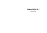
AGU - Address Generation Unit - This block does all the manipulations necessary to
figure out all of the various memory addresses that will be used.
CGDB - Core Global Data Bus - Used for many of the data transfers around the
processor.
Data ALU - Arithmetic Logic Unit - This block performs all of the math that is
performed on data by the DSP.
MAC - Multiply-ACcumulate - This unit does a multiplication and accumulation very
quickly (the core process of a DSP); recall that convolution is defined as a series of
multiply and accumulate operations:
OnCE (JTAG) - On Chip Emulation (Joint Test Action Group) - This is hardware on
the processor that allows real time debugging to be accomplished it; it allows us to
access memory and registers, single step through programs, set breakpoints... It
makes life easier.
PAB - Program Address Bus - This is a 16 bit address bus that determines the address
of the instruction in the program this is to be executed.
PGDB - Peripheral Data Bus - This is a 16 bit data bus that transfers data back and forth
to and from peripherals (e.g., serial ports, A/D and D/A converters.
PDB - Program Data Bus - This is a 16 bit data bus that holds the instruction that is to
be executed.
XAB1 - eXternal Address Bus 1 - This is a 16 bit address bus that is used to specify a
memory location whose contents are to be used as data. XAB1 can be used either for
on-chip or off-chip memory.
XAB2 - eXternal Address Bus 2 - This is another 16 bit address bus that is used to
specify a memory location whose contents are to be used as data. XAB2 can be used
only for on-chip memory. Because there are two of these address buses, two pieces
of data can be fetched simultaneously.
XDB2 - eXternal Data Bus 2 - This 16 bit data bus is used in conjunction with the
CGDB (see above) when simultaneous memory reads (using XAB1 and XAB2) are
performed.
X0, Y0, Y1 - Three general purpose 16 bit registers. Used as input to ALU. Y0 and Y1
can be combined as a 32 bit register.
A0, A1 and A2, B0, B1 and B2 - A0 and A1 are referred to as register A - a 32 bit
register. They can be extended to 36 bits by including A2 (which can be used to
handle overflow).
R0-R3, SP - These registers are used to hold addresses (pointers) to enable quick access
to memory. SP is the stack pointer.
N - Offset register. The value of N can be added to one of the pointers to create a new
address.
M01 - Modifier register. This register is used when Modulo (circular) Addressing is
used.
PC - Program Counter. The PC determines the address of the next instruction to be
executed.
HWS - Hardware Stack . This register is used to support hardware looping. It is only
two levels deep.
Software Stack - This is used as the stack (temporary storage) for most purposes. It is
in X memory, and is variable in size.
SR - Status Register. This has a number of bits that is used to describe the status of the
processor (e.g., how overflows are handled, was the result of the last operation zero?
Was it negative? Did it cause an overflow - we'll look more at this one later). It is
split up into two parts:
MR - Mode Register - This determines the mode of the processor; i.e., how it is
configured (e.g., how overflows are handled). This register is typically written by the
user.
CCR - Condition Code Register - The bits of this register are determined by the
sequence of operations performed (e.g., was the result of the last operation zero?).
This register is typically read by the user.
OMR - Operating Mode Register. The bits in this register determine in which of
several mode the processor is operating.
LA - Loop Address - The memory address of the beginning of the loop.
LC - Loop Counter. Keeps track of how many times a loop has executed.
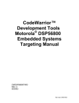
The core is shown in pink, the DSP56824 peripheral registers in green.
COP - Computer Operating Properly - A method for ensuring an embedded program is
working properly. We won't worry about this.
GPIO - General Purpose Input/Output - We will use these to control physical devices;
particularly 3 LED's.
Interrupts - Used to force the processor to perform a particular routine.
Memory - Where data and program are stored.
PLL - Phase Locked Loop - Used to generate clock signals.
RTI - Real Time Interrupt - Hardware used to generate interrupts on a periodic basis
(e.g., for sampling)
SPI - Serial Peripheral Interface - We will use this to communicate with the PC
SSI - Serial Synchronous Interface - We will use this to communicate with the CODEC
(A/D and D/A converter)
Timer/Event Counters - We can use these to keep track of time (e.g., to set a sampling
rate).
The EVM has several peripherals attached will be useful. In particular it has:
•
•
•
•
•
64k of program memory and 64k of data memory - more than we will need.
A JTAG interface so we can do debugging.
A 13 bit A/D and D/A converter (CODEC - Coder/Decoder)
3 LED's (Light Emitting Diodes) that we can use for debugging.
Two push-button switches (not shown) used for input.
Accessing the LED's
The DSP56824 has several General Purpose I/O (GPIO) ports. One of these (called port
B) can be used to control three LED's on the EVM. Port B is controlled by two registers
located in the X memory of the processor. The registers are:
pbddr - Port B Data Direction Register. This register determines whether the
individual pins on port b are inputs or outputs. For example if pbddr is set as shown:
pbddr at memory location 0xffeb
Bit# 15 14 13 12 11 10
Value 0 0 0 0 0 1
9
1
8
1
7
0
6
0
5
1
4
1
3
1
2
1
1
0
0
0
would set bits 10, 9, 8, 5, 4, 3, and 2 as outputs and the rest as inputs.
pbdr - Port B Data Register. This register determines the value of the bits set at port b.
The red, yellow, and green LED's are connected to bits 8, 9 and 10 of port b,
respectively. The pbddr must be used to make sure the pins are outputs. For example,
if pbddr is set as shown above and pbdr is set as shown below
pbdr at memory location 0xffec
Bit# 16 15 14 13 12 11 10
Value 0 0 0 0 0 0 1
9
0
8
1
7
0
6
0
5
0
4
0
3
0
2
0
1
0
0
0
then the red and green LED's (bits 8 and 10) will be on and the yellow LED (bit 9) will
be off.
Using C:
The C compiler has pointers to pbddr and pbdr predefined. To set the registers as
shown above you would use the lines:
*pbddr=0x073c;
*pbdr=0x0500;
//0x073c=0b0000011100111100
//0x0500=0b0000010100000000
Note: Each digit in hexadecimal is color coded in the binary.
Using Assembly:
In assembly language to set the bits you could use the following (note: this code would
not set any of the bits in the registers, it would just ensure that the specified bits are set):
bfset #$073c,x:$ffeb
bfset #$0500,x:$ffec
;Location ffeb is pbddr
;Location ffec is pbdr
We could make this more readable by predefining some constants:
RedGreenOn
PBDDR
PBDR
EQU
EQU
EQU
$0500
$ffeb
$ffec
bfset #$073c,x:PBDDR
bfset #RedGreenOn,x:PBDR
Mixing Assembly into C:
We can also insert individual assembly language instructions into C for direct control of
hardware (and sometimes increased efficiency). For example, the two lines of C code
shown below have the same effect:
1) *pbddr=0x073c;
//0x073c=0b0000011100111100
2) asm(bfset #$073c,x:$ffeb) //Use inline assembly
Interrupts
Often real-time programming utilizes interrupts to handle events asynchronously.
Rather than having a program run and monitor every condition, we allow these
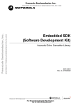
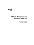
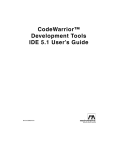
conditions to actually interrupt whatever the processor is doing. The diagram below
shows what happens when an interrupt occurs, in this case from the SSI (Synchronous
Serial Interface).
1. The program is initially executing the main program. After it executes the
MOVE instruction at location $0102 the hardware recognizes an interrupt on the
SSI line.
2. The processor executes one more instruction (while it performs a check of the
priority of the interrupt, among other things) and then set the PC (Program
Counter) to the appropriate interrupt vector. At this point it saves the SR (Status
Register) and the PC (Program Counter) so it can return to the same state. Note
that is does not save any other registers. If your ISR needs to use registers, it
must save them. In C we won't worry about this -- it is handled automatically.
3. The interrupt vector performs a JSR (Jump Subroutine) instruction to the actual
code that performs the desired action in response to the interrupt.
4. The RTI instruction returns the program back to where it came from. The SR
and PC are restored.
5. The program resumes as if nothing happened.
There are two fundamental types of interrupts, maskable (level 0) and non-maskable
(level 1). A maskable interrupt can be turned off (masked), an non-maskable interrupt
cannot. The non-maskable interrupts are used for such things as illegal instructions that
we want to always cause an interrupt. The interrupts that we will use are maskable
interrupts which operate at a lower priority.
Important Registers for the interrupt process.
Two Registers are important for the interrupt process, the IPR (Interrupt Priority
Register) and the SR (Status Register)
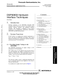
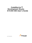
A level sensitive interrupt will generate interrupts whenever the line is low (or high). It
is more common to use an edge triggered interrupt that generates a single interrupt when
the interrupt line goes low. The image below shows the schematic of the IRQA and
IRQB lines.
The resistors normally hold the line (IRQx_IN\ -- the \ denotes that the line is active
(i.e., the button is pushed) when low). So in order to generate an interrupt when the
button is pushed, we will make the interrupts falling-edge sensitive. To do this and
enable the interrupts we should set IxL1 to 1, IxINV to 0 and IxL0 to 1 (x = A or B).
To enable both IRQA and IRQB as falling-edge sensitive interrupts we want to set the
bits in IPR as follows, where x's denote a don't care condition.
We can do this by using a Bit Field SET command:
asm(bfset #$0036, x:0xfffb);
//Recall 36hex=0011 0110binary, and IPR is at location 0xfffb.
Note that technically we should clear the bits we want set to zero - but they should be
zero when the processor resets.
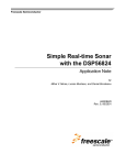
The last thing we have to do is set bits in the SR (Status Register) to enable these
interrupts. The status register is shown below. The only bit we have to worry about is
I0 which enables maskable interrupts (like IRQA and IRQB).
Status Register
asm(bfset #$0100, sr);
//Recall 0100hex=0000 0001 0000 0000binary.
Putting it all together.
Let's write an interrupt routine in C that uses IRQA.
void IRQA_Routine() {
#pragma interrupt
printf("The IRQA button was pushed.");
}
Note that this code has a line telling the compiler that this is an interrupt service routine
(#pragma interrupt). This is important for the compiler because an interrupt
procedure must end with an RTI (ReTurn from Interrupt) instruction, whereas a regular
procedure ends with an RTS (ReTurn from Subroutine) instruction.
Note also that this routine uses printf, which can be a bad idea in an interrupt routine.
If the processor is in the middle of a printf routine and it receives an interrupt that uses
printf, it can get very confused. Nevertheless, we will do this and be careful to write
code where the aforementioned difficulty will not arise.
Before we can use it we have to do 3 things.
1) Write the interrupt vector. For the IRQA interrupt the interrupt vector is at memory
location 0x0010 (recall that the SSI interrupt in the example above was at location
$000E). First we write the JSR instruction (which decode to 0xE98C) and then we
write the address of our routine (&IRQA_Routine). The pmemwrite() function is
included with lesson 4 of the CodeWarriorU DSP56824 tutorial. It writes the specified
data to the program memory (recall that in a Harvard Architecture the program memory
is physically distinct from the data memory). Because the interrupt vector is part of the
program, it must be in the program memory.
//Write the JSR instruction into the IRQA vector at location 0x0010 of
program memory.
pmemwrite((WORD) 0xE98C, (WORD) 0x0010);
//The next memory location holds the address of our interrupt service
routine.
pmemwrite((WORD) &IRQA_Routine, (WORD) 0x0011);
2) Set the appropriate bit in the IPR
//Set IRQA to be falling edge sensitive and enable it.
asm(bfset #$0006, x:0xfffb);
3) Set the appropriate bit in the SR.
//Enable all of the maskable (level 1) interrupts.
asm(bfset #$0100, sr);
That's all there is to it. Now whenever we hit the IRQA button, we will execute the
subroutine.
IRQA_Routine()
Timers & Clocks
To control and respond to process that happen in real time it is often necessary to keep
track of time. In DSP the most obvious manifestation of this need is the sampling
process in which samples must be taken (A/D) or generated (D/A) at the specified
sampling interval. In other application it may be necessary to keep track of the time of
day or to check for an incoming phone call every second or two...
To describe how timers are used to generate periodic interrupts two sets of resources on
the DSP are used, the timers (or counters) and the clock generator. The clock generator
is used to generate a clock or constant frequency square wave. It is relatively
inflexible. The timers are used to count events (e.g., the aforementioned clock) and to
respond after a fixed number of them have been counted. We will discuss timers first,
and then clocks. These topics correspond to chapters 9 and 10 in the DSP56824 User's
Manual, where you can go for more detail.
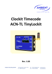
The Timers
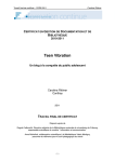
The DSP56824 has three timers called Timer0, Timer1 and Timer2. They are depicted
in the block diagram below.
The three timers obviously have a lot of similarities. They each have a similar input
stage (an exclusive-OR gate followed by a 4-to-1 MUX). They have a 16 bit preload
and 16 bit count register. Each one also has an 8 bit control register. Timer0 and
Timer1 share one 16 bit register (TCR01), with each using 8 bits. Timer2 uses only 8
bits of the 16 bit register TCR2.
The input to each timer can come from one of several sources, chosen by the MUX.
Each low to high transition from the MUX output causes the corresponding count
register to decrement. When the count register gets to zero it generates an overflow
signal, which can have one of several effects (e.g., generating an interrupt). Let's look
quickly at the registers involved.
Registers
TCTx - Timer Count register
This 16 bit register counts down whenever there is a low to high transition on the output
of the MUX.
TPRx - Timer Preload Register
This is a 16-bit register that holds that contains the value to be loaded into the count
register when the corresponding Timer Count Register has counted down to zero.
TCRx - Timer Control Register
The Timer Control Register is the most complex of the three registers. The bit functions
are shown in the image below. The bit functions are described in the text that follows.
TE - Timer Enable
This bit must be set to one to enable the corresponding timer.
INV - INVert
When the TOI bit is used as an input this bit determines whether the input is rising edge
or falling edge sensitive. We won't use this.
OIE - Overflow Interrupt Enable.
This bit allows the overflow of the corresponding timer to trigger an interrupt. The
vector locations are as follows.
Timer Interrupt Vector Location
0 $0018
1 $001A
2
$001C
Note that you still have to enable the interrupt by also setting the appropriate bits in the
IPR and SR. See the section on Interrupts.
TO - Timer Output Enable - This specifies the operation of the TIO pin on the DSP
chip. We will be using internally generated interrupts, so this pin won't matter.
TO[1:0]
TIO Pin Function
00
TIO is input
01
(Reserved)
10
TIO is output - pulses on overflow
TIO is output - toggles on
11
overflow
ES - Event Select
ES[1:0]
Clock Source
00
Internal Phi Clock/4
01
Internal Prescaler Clock
Previous Timer Overflow (Timers 1 &
10
2)
11
External Event form TIO Pin
The bits that are of concern to us are the TE bit (which turns the timer on and off) the
OIE bit (which enable and disables timer interrupts) and the ES bits (which determine
which of the four MUX inputs to feed into the timer).
We will generally drive each timer either from one of the system clocks (Internal Phi
Clock/4, Internal Prescaler Clock) or from the output of the previous timer (Previous
Timer Overflow). We will use the output from the previous timer when we want to
generate long delays. For example, the longest delay from Timer0 might be 3.74 mS. If
we want a 1 second delay we can feed this overflow (every 3.74 mS) into Timer1 and
wait for 267 (267*0.00374 ~= 1) of these overflows to occur to give us our 1 second
delay.
However we will generally use the Phi Clock/4 as our time base. The Phi Clock is
generated from the processor's crystal (which, in our case, runs at 3.6864 MHz), and
determines how fast the processor actually runs. The Phi Clock is run through a PLL
(Phase Locked Loop) which generates a clock frequency that is actually higher than the
input clock frequency by an amount that is programmable. We want the processor to
run at 70 MHz, so we want the PLL to generate a signal that is 19 times higher than the
crystal frequency (19*3.6864 MHz ~= 70 MHz). To do this we need to program the
clock synthesis portion of the DSP56824.
Clock Synthesis
The clock synthesis portion of the hardware is shown in light green on the left of the
diagram below. The clock feeds many parts of the processor. In particular it feeds the
timer module which we examined above.
The clock synthesis is controlled predominantly by two registers, PCR0 and PCR1, the
Phase Locked Loop Control Registers. Let's examine PCR0 first.
PCR0
This register holds the PLL multiplier+1. In our case since we want a multiplier of 19
(to get a 70 MHz clock from a 3.6864 MHz crystal) we put a value of 20
(000010100binary) into bits 5 through 14 of the register. So four our purposes
PCR0=0000 0010 1000 0000binary=0x0280 (the pertinent bits are bold)
The other register is more complicated. Let's quickly run through the bits.
PCR1
PLLE - PLL Enable - We will set this to 1 to enable the PLL.
PLLD - PLL Power Down - This bit should be cleared to put the PLL in active mode.
We will set this bit to 0.
LP - Low Power Stop - The low power stop it is used to places the chip in a low power
configuration when stopped. It is not critical for our application. However, we will set
this bit to 0.
PSx - Prescaler Divide - Another clock signal can be generated by the clock synthesis
module with the prescaler. The bits (PS[2:0]) determine whether to divide, disable or
deliver the oscillator clock. It is most often used to drive the COP timer and real time
clocks. The bits function as given in the table. We will set these bits to 010.
TSTEN / CSx - Test Enable / CLK0 Select - Chooses which signal to use for CLK0.
We will set these bits to 000.
VCS - Voltage Controlled Oscillator (VCO) curve select - If this bit is zero, the VCO is
optimized for 40 to 70 MHz. If it is set to one, the VCO is optimized for 10 to 40 MHz
operation. We are operating at 70 MHz, so will set this bit to 0.
Summary: We will set PCR0=0000 0010 1000 0000binary=0x0280, PCR1=0100 0010
0000 0000binary=0x4200 (pertinent bits are in bold).
SSI & CODEC
The DSP needs a way to exchange data with the real world. This is done with the
CODEC (COder DECoder -- a separate chip) and the SSI (Synchronous Serial Interface
-- an on chip peripheral). The CODEC is simply an A/D converter (the COder) to get
analog values into the DSP and a D/A converter (the DECoder). The SSI is a serial port
that is used to transmit data back and forth between the CODEC and the DSP. We will
look only briefly at the SSI registers needed to set up a regular sampling interval and to
correctly process the data. We will then briefly look at the CODEC, though there is
little we can do to program it.
You can get more information about the SSI in the DSP56824 User's Manual. The
CODEC is described in the Product Preview MC145483. The actual circuit diagrams
that are pertinent for us are in the DSP56824 Evaluation Module Hardware Reference
Manual.
The SSI
The registers that we need to program to get the SSI working properly are PCC,
SCRRX, SCRTX, SCR2, and the IPR (Interrupt Priority Register - to enable the SSI
interrupts). I will not cover the IPR since we discussed that previously.
I will start with the PCC (Port C control register) which must have certain bits set so
that the SSI (an internal peripheral)
In particular, we need to set bit 13 through bit 8 to a logic 1. For more detail see
DSP56824 User's Manual, Chapter 8.
After this, we need to configure the SSI control Register 2 (SCR2). I will only briefly
describe each bit. Most of the bit specifications are specified by the CODEC and the
EVM circuitry. I won't go into detail on each bit, but will give the logic level (and a
brief description of each). For more details see DSP56824 User's Manual, Chapter 8.
Bit 15 - RIE=1 - Receive Interrupt Enable: We will set this to one, allowing interrupts
when data is received from the SSI (which is connected to CODEC). The interrupt
vector is given below. One vector is used when there is an error in transmission,
another for no error. We will set these to the same place and hope for no errors.
Vector
Receive with exception
Receive without
exception
Interrupt Vector Location
$0020
$0022
Bit 14 - TIE=0 - Transmit Interrupt Enable: We will set this to zero. We will simply
transmit a word to the D/A for every word we get from the A/D (and received via the
Receive Interrupt).
Bit 13 - RE=1 - Receive Enable: We will set this to one, enabling the receive register.
Bit 12 - TE=1 - Transmit Enable: We will set this to one, enabling the transmit register
Bit 11 - RBF=0 - Receive Buffer Enable: We will set this to zero, which ensures that we
will get an interrupt after each datum is received from the CODEC. If the buffer is
used, an interrupt is generated only after two data are received.
Bit 10 - TBF=0 - Transmit Buffer Enable: We will set this to zero, so data is sent
immediately upon being written to transmit register. Similar to RBF.
Bit 9, 8, 7 - RXD=0, TXD=1, SYN=1. RXD is the Receive Transmit Direction, TXD is
the Transmit Receive Direction, and SYN is the Synchronous mode. By setting them as
specified the transmitter and receiver are clocked internally and share clock lines.
Bit 6 - SHFD=0 - SHiFt Direction: Data is transmitted with the most significant bit
first.
Bit 5 - SCKP=0 - ClocK Polarity: Data is clocked out on the rising edge.
Bit 4 - SSIEN=1 - SSI ENable: Set to one to enable the SSI.
Bit 3 - NET=0 - NETwork mode: Set this to zero since we are not on any kind of
network.
Bit 2 - FSI=0 - Frame Sync Invert: This bit controls the logic of the frame sync. Frame
sync is active high when FSI=0.
Bit 1 - FSL=1 - Frame Sync Length: If FSL is set, the frame sync bit is only one clock
period long.
Bit 0 - EFS=0 - Early Frame Sync: By clearing FSL the frame sync is initiated as the
first bit of data is received or transmitted.
Before you can understand SCRRX and SCRTX you need to understand a little of the
hardware.
There are several counters on board the DSP56824 that are used by the SSI to generate
evenly spaced interrupts. These counters divide down the Phi clock to something near 8
kHz for our operations. A block diagram is shown below. The numbers in blue give
the clock rates for the configuration we will be using.
We will use the Phi Clock at 40.55 MHz.
Bit 15 - PSR=0 - Prescaler Range is zero, so the prescaler is set to 1. The input
frequency is 20.275 MHz, as is the output frequency.
Bits 7-0 - PM[7:0]=0000 01002=410. Setting the Prescaler Modulus select to 4 gives a
divide by 5 at this stage. The input frequency is 20.275 MHz and the output is 4.055
MHz.
Bits 14-13 -WL[1:0]=112. Setting these bits both to 1 gives a sixteen bit word length.
The word length of the CODEC is only 13 bits -- we'll have to make an adjustment for
this in our software. The input frequency is 2.0275 MHz, the output is 126.7 kHz.
Bits 12-8 - DC[4:0]=0 11112=1510. Setting the frame rate Divider Control to 15 sets the
frame divider to divide by 16 giving us a sampling rate near 8 kHz. The input to this
stage is 126.7 kHz, the output is 7.92 kHz.
The only registers left are the SRX and the STX. We read from the SRX when data has
been received from CODEC's A/D by SSI. We write to the STX when we want to send
data to the CODEC's D/A.
The only other register that will concern us at all is the SCSR, the SSI Control/Status
Register (referred to as the SSR in the CodeWarrior Documentation).
We are only concerned with bit RFSL (Receive Frame Sync Length) which is set
whenever a word is received. I couldn't figure out why -- you could try setting it in the
initialization code instead of the Interrupt Service Routine. This could be a bug in the
DSP hardware, poor coding of the software, or some subtlety of the hardware of which I
am unaware.
That's all there is to it. Let's look at some isolate sections of the code we'll use to see
what they do.
Some Relevant DSP Code
//*******************Start of Section*****************
//Set Oscillator near 40 MHz
*PCR0 = (PLL_MUL-1)<<5; // 3.6864 MHz * 11 = 40.5504MHz
*PCR1 = 0x4208; // Enable PLL
//*********************End of Section*****************
//*******************Start of Section*****************
*PCC = 0x3f00; // PortCC[13-8]=1 enable ssi peripheral
*SCRRX = 0x6F04; //PSR=0, WL=3, DC=15, PM=4
*SCRTX = 0x6F04; // PSR=0, WL=3, DC=15, PM=4
*SCR2 = 0xB182; // RIE=1, TIE=0, RE=1, TE=1 ...
*IPR |= 0x200; // Enable SSI interrupts
*SCR2 |= 0x0010; // SSIEN=1
//*********************End of Section*****************
//*******************Start of Section*****************
// SSI Interrupt Handler
void SSI_rx_isr(void)
{
#pragma interrupt
int status;
short data;
__fixed__ data1;
*SSR |= 0x0200; // set rfsl
status = *SSR; // read the status reg
data = *SRX; // read the receive reg
data1 = __int2fixed((data << CODEC_BIT_SHIFT)); // adjust the data
data1 = fir_filter(data1,FIRCoefs,numTaps,histBuff);
data = ((__fixed2int(data1)) >> CODEC_BIT_SHIFT); // readjust the data
*STX = data; // put into transmit reg
} // end SSI_rx_isr()
//*********************End of Section*****************
//*******************Start of Section*****************
/* Low-pass filter coefficients */
__fixed__ FIRCoefs[] = {
CFF( -0.00146148), CFF( -0.00302057), CFF( -0.00535611), CFF( 0.00789890),
CFF( -0.00986130), CFF( -0.01015001), CFF( -0.00754271), CFF( 0.00095777),
CFF( 0.01023872), CFF( 0.02595341), CFF( 0.04522235), CFF(
0.06623663),
CFF( 0.08657257), CFF( 0.10358802), CFF( 0.11490465), CFF(
0.11887384),
CFF( 0.11490465), CFF( 0.10358802), CFF( 0.08657257), CFF(
0.06623663),
CFF( 0.04522235), CFF( 0.02595341), CFF( 0.01023872), CFF( 0.00095777),
CFF( -0.00754271), CFF( -0.01015001), CFF( -0.00986130), CFF( 0.00789890),
CFF( -0.00535611), CFF( -0.00302057), CFF( -0.00146148) };
/* Global variables */
short dataArr[BUFLEN];
short numTaps = sizeof(FIRCoefs)/sizeof(__fixed__);
__fixed__ histBuff[37];
//*********************End of Section*****************
The CODEC
A block diagram of the CODEC is shown below. We won't worry about most of the
signals, but it is good to have some idea of what is contained there.
The Purple Section on the right takes care of all the logic involved with transmitting
information back and forth to and from the DSP.
The Green Section is the heart of the CODEC with the actual A/D and D/A converter.
The Yellow section has several Op-Amps that can be used for signal conditioning,
amplification... There is also an amplifier that generates a virtual ground midway
between Vdd and Vss (3.3 and 0 Volts), since there is no negative power supply on this
device. There is an internal gain setting that can be set by transmitting 3 bits. Recall
that we sent 16 bits to the CODEC but only 13 bits were D/A values. The other 3 bits
are a gain for the A/D -- we will always set them to zero.
The Red Section contains an 8th order low pass anti-aliasing filter (one pole is and RC
active filter, 7 poles are switched capacitor). It also has an optional 3rd order switched
capacitor high-pass filter. The high-pass filter is selected by setting HB to ground. We
will generally not use this option.
The Blue Section contains a 7th order low-pass filter (5 poles are switched capacitor,
and 2 poles are active RC). It also has sin(x)/x correction (more on that later in the
semester).
The CODEC on the EVM
The CODEC as implemented on the EVM is shown below.
The Blue Section contains circuitry for input scaling and conditioning.
The Red Section contains circuitry for output scaling and conditioning.
The Green Section contains the jumper that selects or deselects the high-pass filter. We
will generally have it deselected.
The rest of the circuitry is necessary to set internal voltages or to interface with the
DSP.
Assembly Language Instructions
I will try to keep a running list of important assembly language instructions. This will
be a subset of the full complement of instructions described in the DSP56800 Family
Manual (either Chapter 6 or Appendix A) The descriptions below are quite brief, you
can get fuller descriptions in the DSP56800 Family Manual. You may need to look up
additional instructions for some labs.
bfclr #data,location - test Bit Field and CLeaR - Whatever bits are set in data will be
cleared in the memory at location. It does not change bits in the specified memory
location that are already set to 1. It also does some tests (see manual).
bfset #data,location - test Bit Field and SET - Whatever bits are set in data will be set in
the memory at location. It does not change bits in the specified memory location
that are already set to 1. It also does some tests (see manual).
debug - returns the program to the debugger.
eor - exclusive or.
jsr - Jump Subroutine - this causes the program to go to a subroutine. However the
contents of the program counter are saved so that the program can return whence it
came.
move #data,location - This instruction moves the quantity data to the specified memory
location, overwriting all bits.
nop - No OPeration - This instruction does nothing. It is used primarily for delays in a
loop.
rti - ReTurn from Interrupt - This is placed at the end of an interrupt service routine to
return the program to the spot in memory where it was running before the interrupt
occurred.
rts - ReTurn from Subroutine - This is placed at the end of an interrupt service routine
to return the program to the spot in memory where it was running before the jsr
(Jump to Subroutine) instruction occurred.
All Acronyms
AGU - Address Generation Unit - This block does all the manipulations necessary to
figure out all of the various memory addresses that will be used.
A0, A1 and A2, B0, B1 and B2 - A0 and A1 are referred to as register A - a 32 bit
register. They can be extended to 36 bits by including A2 (which can be used to
handle overflow).
CGDB - Core Global Data Bus - Used for many of the data transfers around the
processor.
CODEC - COder/DECoder - Essentially and A/D and D/A converter.
COP - Computer Operating Properly - A method for ensuring an embedded program is
working properly. We won't use this.
Data ALU - Arithmetic Logic Unit - This block performs all of the math that is
performed on data by the DSP.
GPIO - General Purpose Input/Output - We will use these to control physical devices;
particularly 3 LED's.
HWS - Hardware Stack . This register is used to support hardware looping. It is only
two levels deep.
Interrupts - Used to force the processor to perform a particular routine.
IPR - Interrupt Priority Register - The bits in this register determine how the processor
deals with interrupts.
IRQ - Interrupt ReQuest
LC - Loop Counter. Keeps track of how many times a loop has executed.
MAC - Multiply-ACcumulate - This unit does a multiplication and accumulation very
quickly (the core process of a DSP)
Memory - Where data and program are stored.
M01 - Modifier register. This register is used when Modulo (circular) Addressing is
used.
N - Offset register. The value of N can be added to one of the pointers to create a new
address.
OMR - Operating Mode Register. The bits in this register determine in which of
several mode the processor is operating.
OnCE (JTAG) - On Chip Emulation (Joint Test Action Group) - This is hardware on
the processor that allows real time debugging to be accomplished it; it allows us to
access memory and registers, single step through programs, set breakpoints... It
makes life easier.
PAB - Program Address Bus - This is a 16 bit address bus that determines the address
of the instruction in the program this is to be executed.
PC - Program Counter. The PC determines the address of the next instruction to be
executed.
PDB - Program Data Bus - This is a 16 bit data bus that holds the instruction that is to
be executed.
PGDB - Peripheral Data Bus - This is a 16 bit data bus that transfers data back and forth
to and from peripherals (e.g., serial ports, A/D and D/A converters.
PLL - Phase Locked Loop - Used to generate clock signals.
R0-R3, SP - These registers are used to hold addresses (pointers) to enable quick access
to memory. SP is the stack pointer.
SPI - Serial Peripheral Interface - We will use this to communicate with the PC
Software Stack - This is used as the stack (temporary storage) for most purposes. It is
in X memory, and is variable in size.
SR - Status Register. This has a number of bits that is used to describe the status of the
processor (e.g., was the result of the last operation zero? Was it negative? Did it
cause an overflow - we'll look more at this one later).
SSI - Serial Synchronous Interface - We will use this to communicate with the CODEC
(A/D and D/A converter)
TCTx - Timer Count register - a 16 bit count down register. (x can be 0, 1 or 2)
Timer/Event Counters - We can use these to keep track of time. We will use them
primarily to set our sampling rate.
TPRx - Timer Preload Register - This 16-bit register holds the value loaded into the
count register when it gets to zero. (x can be 0, 1 or 2)
TCRx - Timer Control Register - TCR01 is a 16 bit register that holds the two 8 bit
control registers for timers 0 and 1. TCR2 uses only 8 bits that comprise the timer 2
control register. (x can be 01 or 2)
XAB1 - eXternal Address Bus 1 - This is a 16 bit address bus that is used to specify a
memory location whose contents are to be used as data. XAB1 can be used either for
on-chip or off-chip memory.
XAB2 - eXternal Address Bus 2 - This is another 16 bit address bus that is used to
specify a memory location whose contents are to be used as data. XAB2 can be used
only for on-chip memory. Because there are two of these address buses, two pieces
of data can be fetched simultaneously.
XDB2 - eXternal Data Bus 2 - This 16 bit data bus is used in conjunction with the
CGDB (see above) when simultaneous memory reads (using XAB1 and XAB2) are
performed.
X0, Y0, Y1 - Three general purpose 16 bit registers. Used as input to ALU. Y0 and Y1
can be combined as a 32 bit register.
References
Many of the images, and most of the information, on this page came from these
publications.
•
•
•
•
•
DSP56800 Family Manual (Motorola Part #DSP56800FM/D)
DSP56824 User's Manual (Motorola Part #DSP56824UM/D)
DSP56824 Evaluation Module Hardware Reference Manual (Motorola Part
#DSP56824EVMUM/D)
DSP56824 Data Sheet (Motorola Part #DSP56824/D)
Product Preview MC145483 (Motorola Part #MC145483/D)