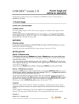
1
user manual
chromatography software
UNICORN Version 3.20
Frac-950 module for UNICORN applications
um 18-1138-53AB, 2000-07
to order:
Asia Pacific Tel: +852 2811 8693 Fax: +852 2811 5251 Australasia Tel: +61 2 9894 5152 Fax: +61 2 9899 7511
Austria Tel: 01 576 0616 20 Fax: 01 576 0616 27
Belgium Tel: 0800 73 888 Fax: 03 272 1637 Canada Tel: 1 800 463 5800 Fax: 1 800 567 1008 Central, East, South East Europe Tel: +43 1 982 3826 Fax: +43 1 985 8327
Denmark Tel: 45 16 2400 Fax: 45 16 2424 Finland Tel: 09 512 3940 Fax: 095121710 France Tel: 0169 35 67 00 Fax: 0169 41 9677
Germany Tel: 0761 4903 401
Fax: 0761 4903 405 Italy Tel: 02 27322 1 Fax: 02 27302 212 Japan Tel: 81 3 5331 9336 Fax: 81 3 5331 9370 LatinAmerica Tel: +55 11 3667 5700
Fax: +55 11 3667 87 99 Middle East and Africa Tel: +30 (1) 96 00 687 Fax: +30 (1) 96 00 693 Netherlands Tel: 0165 580 410 Fax: 0165 580 401 Norway Tel: 2318 5800
Fax: 2318 6800 Portugal Tel: 01 417 7035 Fax: 01 417 3184 Russian Federation Tel: +7 (095) 232 0250,956 1137 Fax: +7 (095) 230 6377 South East Asia Tel: 60 3 724 2080
Fax: 60 3 724 2090 Spain Tel: 93 594 49 50 Fax: 93 594 49 55 Sweden Tel: 018 612 19 00 Fax: 018 612 19 10 Switzerland Tel: 01 802 81 50 Fax: 01 802 81 51
UK Tel: 0800 616 928 Fax: 0800 616 927 USA Tel: +1 800 526 3593 Fax: +1 800 329 3593
BioPilot, BioProcess, UNICORN, and ÄKTA are trademarks of Amersham Biosciences Limited or its subsidiaries. Amersham is a trademark of Nycomed Amersham plc.
Microsoft and Windows NT are trademarks of the Microsoft Corporation. Amersham Biosciences
AB Björkgatan 30, SE-751 84 Uppsala, Sweden. Amersham Biosciences UK Limited Amersham Place, Little Chalfont, Buckinghamshire HP7 9NA, England.
Amersham Biosciences Inc 800 Centennial Avenue, PO Box 1327, Piscataway, NJ 08855 USA. Amersham Biosciences Europe GmbH Munzinger Strasse 9, D79111 Freiburg, Germany. All goods and services are sold subject to the terms and conditions of sale of the company within the Amersham Biosciences group that supplies
them. A copy of these terms and conditions is available on request. © Amersham Biosciences AB 2000 - All rights reserved.
CONTENTS
Frac-950 Setup and Documentation
1.1 Introduction . . . . . . . . . . . . . . . . . . . . . . . . . . . . . . . . . . . . . . 3
1.2 Method editor: Run Setup . . . . . . . . . . . . . . . . . . . . . . . . . . 4
1.2.1 Rack type . . . . . . . . . . . . . . . . . . . . . . . . . . . . . . . . . . . . . . . 4
1.2.2 Fraction order . . . . . . . . . . . . . . . . . . . . . . . . . . . . . . . . . . . . 5
1.3 System control . . . . . . . . . . . . . . . . . . . . . . . . . . . . . . . . . . . 5
1.3.1 Last tube . . . . . . . . . . . . . . . . . . . . . . . . . . . . . . . . . . . . . . . . 5
1.4 Evaluation . . . . . . . . . . . . . . . . . . . . . . . . . . . . . . . . . . . . . . . 6
1.4.1 Documentation . . . . . . . . . . . . . . . . . . . . . . . . . . . . . . . . . . . 6
1.4.2 Fraction text alignment. . . . . . . . . . . . . . . . . . . . . . . . . . . . . . 7
A Strategy for ÄKTAexplorer 100
A.1 Method instructions . . . . . . . . . . . . . . . . . . . . . . . . . . . . . A-1
A.1.1
A.1.2
A.1.3
A.1.4
A.1.5
A.1.6
Pump . . . . . . . . . . . . . . . . . . . . . . . . . . . . . . . . . . . . . . . . A-1
Flowpath . . . . . . . . . . . . . . . . . . . . . . . . . . . . . . . . . . . . . . A-4
Frac . . . . . . . . . . . . . . . . . . . . . . . . . . . . . . . . . . . . . . . . . A-6
Alarms & Monitors . . . . . . . . . . . . . . . . . . . . . . . . . . . . . . . A-9
Watch . . . . . . . . . . . . . . . . . . . . . . . . . . . . . . . . . . . . . . . A-10
Other . . . . . . . . . . . . . . . . . . . . . . . . . . . . . . . . . . . . . . . . A-11
A.2 Manual control . . . . . . . . . . . . . . . . . . . . . . . . . . . . . . . . A-13
A.2.1
A.2.2
A.2.3
A.2.4
A.2.5
Pump . . . . . . . . . . . . . . . . . . . . . . . . . . . . . . . . . . . . . . .
Flowpath . . . . . . . . . . . . . . . . . . . . . . . . . . . . . . . . . . . . .
Frac . . . . . . . . . . . . . . . . . . . . . . . . . . . . . . . . . . . . . . . .
Alarms & Monitors . . . . . . . . . . . . . . . . . . . . . . . . . . . . . .
Other . . . . . . . . . . . . . . . . . . . . . . . . . . . . . . . . . . . . . . . .
A-13
A-13
A-13
A-14
A-15
A.3 System settings instructions . . . . . . . . . . . . . . . . . . . . A-15
A.3.1
A.3.2
A.3.3
A.3.4
Alarms. . . . . . . . . . . . . . . . . . . . . . . . . . . . . . . . . . . . . . .
Specials. . . . . . . . . . . . . . . . . . . . . . . . . . . . . . . . . . . . . .
Monitors . . . . . . . . . . . . . . . . . . . . . . . . . . . . . . . . . . . . .
Curves . . . . . . . . . . . . . . . . . . . . . . . . . . . . . . . . . . . . . . .
A-15
A-17
A-18
A-20
B Technical Specifications
B.1 System Requirements . . . . . . . . . . . . . . . . . . . . . . . . . . . B-1
• p1
B.1.1 Hardware requirements . . . . . . . . . . . . . . . . . . . . . . . . . . B-1
B.1.2 Software requirements . . . . . . . . . . . . . . . . . . . . . . . . . . . B-1
B.1.3 Network requirements . . . . . . . . . . . . . . . . . . . . . . . . . . . B-1
B.2 Control Capacity . . . . . . . . . . . . . . . . . . . . . . . . . . . . . . . .B-2
B.2.1 Stand-alone installations . . . . . . . . . . . . . . . . . . . . . . . . . . B-2
B.2.2 Network installations. . . . . . . . . . . . . . . . . . . . . . . . . . . . . B-2
C Installation of the PCI expansion card . . . . . . . . C-1
INDEX . . . . . . . . . . . . . . . . . . . . . . . . . . . . . . . . . . . . . . . . i
• p2
1
1 Frac-950 Setup and Documentation
1.1 Introduction
UNICORNTM is a control system developed and marketed by
Amersham Biosciences AB for real-time control of
chromatographic separation systems from a personal computer. The
package operates together with systems in the ÄKTATMdesign
platform (referred to as ÄKTAdesign systems), BioPilotTM System and
BioProcessTM System from Amersham Biosciences. Standard
configurations are provided for ÄKTAdesign systems and BioPilot
System, while configurations for process-scale separation with
BioProcess System may be customised for a particular installation.
UNICORN runs under the operating system MicrosoftTM Windows
NTTM version 4.0.
This manual describes the functions of the fraction collector Frac-950
within UNICORN 3.20. For a detailed background on other
UNICORN functions, the user is referred to the UNICORN 3.10
manual (for a detailed description of the Frac-950 functions, see the
Fraction collector Frac-950 user manual).
Functional features of Frac-950 include:
•
•
•
User-defined rack choice, including tubes and microtubes.
A variety of sampling orders during the fractionation process.
Method templates, providing method frameworks for fractionation
applications, eliminating the need to program methods from scratch.
For the purposes of this user manual, examples are displayed for an
ÄKTAexplorer 100 system. You should refer to the user instructions
specific to the chromatography system that you are using.
In this manual, menu commands, the names of dialogue boxes and
windows, the contents of dialogue boxes windows, and option buttons
are written with a bold helvetica typeface. Menu commands are
written in the order of the menu name and then the command,
separated by a colon. For example:
“Select File:Save As to display the Save As dialogue. Locate the
destination drive and folder and enter a file name. Click on Save.”
This directs you to click on the File menu and select the command,
Save As. A dialogue called Save As is displayed in which you must
locate the destination folder for the saved file and give the file a name.
You then click on the button called Save in the dialogue to execute the
save command.
• p3
1
1.2 Method editor: Run Setup
User-defined options for Frac-950 are selected on the Frac-950 tab in
Run Setup in the Method editor. To reach Method editor from the
Main menu, create a new method as described in the UNICORN 3.10
manual. To access the Frac-950 tab in Run setup, either click on the
Run setup icon on the toolbar, or select View:Run Setup from the
menu. The Frac-950 tab allows the user to choose rack type, the
fractionation order, and the last tube position
Note: The Frac-950 tab is only available if your strategy supports Frac-950.
Figure 1-1. The Frac-950 tab.
1.2.1 Rack type
Begin the fractionation set up by choosing the appropriate rack type
from the Rack drop-down menu.
Figure 1-2. The Rack drop down menu within the Frac-950 tab.
um
18-1138-53AB • p4
1
1.2.2 Fraction order
Next, use the Fraction order radio buttons to choose the appropriate
order for fractionation.
Figure 1-3. The Fraction order radio buttons.
1.3 System control
In System control, for manual runs, the Frac-950 tab cannot be used in
Documentation. Instead, use the manual fractionation instructions,
starting with Man_ (see also Appendix A, Manual control).
1.3.1 Last tube
The last tube position can only be selected from within Start Protocol
before starting a run. Click the Define box within the Last tube panel,
and then move the cursor over the appropriate tube (circle) within the
tube matrix and click again.
• p5
1
Figure 1-4. The Frac-950 tab, illustrating the Last tube function.
If the fractionation process proceeds beyond this position during a run,
an alarm will be executed. The lower right box within the Last tube
panel shows the currently selected last tube.
If a new last tube has been chosen, but the user wishes to return to the
default last tube position, simply click on the Set default button. This
will automatically set the last tube to its default position.
Note: When using different sized tubes (racks: 18mm tubes or Microplates)
the last tube can be set for both tube sizes. Use the Tube type drop
down menu to choose the desired tube size, and then follow the
procedures outline above to select the last tube.
Note that the total number of tubes sampled may differ according to
which Fraction order has been chosen.The Number of tubes equation
in the bottom left corner of the Frac-950 tab shows the current number
of available tubes chosen for fractionation, followed by the total
possible number in parentheses. For example, in the figure above, 120
of the total 120 small tubes, and all 8 of the large tubes will be
available for fractionation.
1.4 Evaluation
1.4.1 Documentation
The Frac-950 tab can be displayed within the Evaluation module by
um
18-1138-53AB • p6
1
choosing View:Documentation, or pressing the Documentation icon on
the toolbar, and pressing the Frac-950 tab. You can print out the
selected settings by pressing the Print button, or return to the main
Evaluation window by pressing OK or Cancel.
Figure 1-5. The Frac-950 tab in Documentation in the Evaluation module.
1.4.2 Fraction text alignment
In the Evaluation module, click on the chromatogram with the righthand mouse button, select Properties... from the menu and then select
the Curve Style and Colour tab. This will allow you to select Vertical,
Horizontal, or Fly Over orientation for the Fraction text mark.
• p7
1
Figure 1-6. The chromatogram layout dialogue, with the Fraction text alignment
box highlighted.
To change the fraction text alignment from the default option
(horizontal), select the appropriate radio button, and then click on the
OK button.
Figure 1-7. A chromatogram window in the Evaluation module, showing
Vertical fraction text mark alignment.
um
18-1138-53AB • p8
A
Strategy for ÄKTAexplorer 100
A dedicated strategy is available for each system in the ÄKTAdesign
platform. The instructions available differ slightly between strategies,
although the majority are common. To find a description of any
instruction in your particular strategy, mark the instruction and click
on <F1>. To obtain a printout of the instructions, select File:Print in
the Method editor and click on the Instruction set option box.
As an example, this appendix lists the instructions for methods,
manual control and system settings supported by the strategy for
ÄKTAexplorer 100 with Frac-950 (E100F200).
A.1
Method instructions
A.1.1
Pump
Instruction
Description
Parameters
Flow
Starts the flow for the gradient pump at the set flow rate
Flow rate
(0-100 ml/min)
Gradient
Defines a linear gradient for
gradient pump (pump A and
B). Reaches the target value
after the specified length.
Length is expressed in time,
volume or column volume
depending on selected base.
Target
(0-100 %B)
Length
(0-9999 base)
BufferPrep_pH
Selects pH for a defined BufferPrep recipe. When BufferPrep is not used, the
instruction should be set to
zero, otherwise an alarm will
be given.
pH
(0-14)
SampleFlow
Starts the flow of the sample
pump at the set flow rate. The
sample pump can be calibrated in the calibration module.
Flow rate
(0-5 ml/min)
• A1
um
18-1138-53AB • A2
DirectLoad
The sample is directly loaded
onto the column. ReduceFlow
makes it possible to automatically reduce the flow during
sample loading to avoid a
pressure alarm. An alarm will
be received if the flow is lower
than the flow specified in
MinFlow. If an alarm is executed and the run is continued
by pressing Continue, the
sample loading will be
stopped and the run will continue.
SampleFlow
(0-50)
Volume
(0-1000)
ReduceFlow
No
Yes
MinFlow
(OFF, 0.1-49.9) ml/
min
PumpWashExplorer
PumpWash is used to change
eluents in the inlet tubings,
pump and mixer. THE
PUMPS MUST BE PURGED
PRIOR TO USING PUMPWASH. Flow is diverted to
the waste position of the
injection valve. Up to four
inlets can be washed simultaneously; InletA1, InletA2,
InletB1 or Inlet B2. One of the
eight inlets of buffer valve A1
can be selected for InletA1.
The system is set to Pause
during PumpWash and the
pressure limit is set to the
value given in instruction
Wash_alarm_pressure in System:Settings. After PumpWash the injection valve turns
back to its previous position
and the flow and pressure limits are set to their previous
values.(Flow rate: 25 ml/min,
Wash volume: 30 ml/inlet).
InletA1
OFF
(A11-A18)
InletA2
OFF
ON
InletB1
OFF
ON
InletB2
OFF
ON
PumpWashPurifier
PumpWashBasic
PumpWash instructions for
ÄKTApurifier and
ÄKTAbasic, respectively.
-
SystemWash
SystemWash is used to change InletA1
eluents in the system, includ(A11-A18)
ing inlet tubings, pumps,
mixer and flow cells. THE
PUMPS MUST BE PURGED
PRIOR TO USING SYSTEMWASH. Flow is diverted
to the waste at the outlet
valve. The ColumnPosition is
set to Position1Bypass during
SystemWash. One inlet can be
selected, A11-A18. When running BufferPrep methods the
SystemWash instruction will
deliver buffer with the
selected composition (Recipe
and BufferPrep_pH). The system is set to Pause during SystemWash and the pressure
limit is set to the value given
in instruction Wash_alarm
_pressure in System:Settings. After SystemWash the
OutletValve and ColumnValves turn back to their previous positions and the flow
and pressure limit are set to
their previous values.(Flow
rate: 25 ml/min, Wash volume: 75 ml)
MethodBase
Sets the method volume calcu- Base
lation from either GradientGradientPump
Pump or SamplePump
SamplePump
• A3
A.1.2
um
18-1138-53AB • A4
Flowpath
Instruction
Description
Parameters
InjectionValve
Sets the Injection Valve positions. The
Injection Valve is switched to position
1 with parameter "load", to position
2 with parameter "inject" and to
position 3 with parameter "waste".
The instruction gives an injection
mark when the injection valve
switches to the "inject" position.
Position Load
Inject Waste
ColumnPosition
Selects the position for the column.
ColumnPosition switches the two column valves at the same time.
Position1Bypass corresponds to a
tubing connected to valve port 1 and
Position2 corresponds to a column
connected to valve port 2, etc. The
flow rate is reduced to 0 ml/min when
the valves switch.
Position
Position1Bypass,
Position2-8)
OutletValve
Selects the position for the Outlet
valve. Feed switches the outlet valve
one step forward from its actual position. The OutletValve gives fraction
marks.
Position
(WasteF1 FracF2
F3-F8 Feed)
BufferValveA1
Selects the position for Buffer Valve
A1. Position A11 corresponds to
position 1 on the Buffer Valve A1,
position A12 to position 2, etc.The
flow rate is reduced to 0 ml/min when
the valve is switched.
Position (A11A18)
PumpAInlet
Sets the position of the pump A inlet.
The instruction is not allowed in a
method when running BufferPrep
(gives an alarm in BufferPrep mode).
Position A1 A2
PumpBInlet
Sets the position of the pump B inlet.
The instruction is not allowed in a
method when running BufferPrep
(gives an alarm in BufferPrep mode).
Position B1 B2
SampleValve
Selects the position for the SampleValve.
Position (S1-S8)
FlowDirection
Sets the flow direction for the column. The instruction is useful for
example when cleaning columns. The
instruction switches the Flow Direction Valve to position 2 with parameter UpFlow and to position 1 with
parameter DownFlow. The flow rate
is reduced to 0 ml/min when the valve
switches.
Direction
Downflow
Upflow
InjectionMark
The instruction gives an injection
mark. The instruction is useful when
the sample is introduced onto the column with the gradient pump.
-
• A5
A.1.3
um
18-1138-53AB • A6
Frac
Instruction
Description
Parameters
Fractionation
Starts fraction collection if the fraction size specified by the FracSize
parameter is >0. Tube change is
delayed with respect to the set delay
volume. FractionCollector is
stopped with the instruction FractionationStop.
Parameters:
Tube type: The tube type to fractionate in
FracSize: The size of the fractions
Start at: Where to start the fractionation, if a specific position is
desired use Tube number
Base: The fractionation can be performed in time or volume base.
TubeType
FracSize
(0.000 99999.999)
base
StartAt
(First tube
Next tube
Next line
Next group
Tube number)
Base
(Volume
Time)
FractionationStop
Stops fraction collecting after the
set delay volume has been collected.
The flow is diverted to the waste of
the outlet valve.
-
FeedTube
During Fractionation or
Peak_Fractionation, FeedTube
moves the tube rack forward one
tube after the set delay volume has
been collected. A fraction mark is
given.
-
Peak_Fractionation
Peak_Fractionation enables only
peaks to be collected. The UV monitor is used to determine when there
is a peak to collect. PeakSize determines max volume to be collected
in each tube. To collect the peak in
one tube set PeakSize>peak volume.
If Peak_FracParameters are not set
in the method, default values in system settings will be used. Tube
change is delayed with respect to
the delay volume. To stop PeakFractionation use the instruction
Peak_FracStop.
Parameters:
Tube type: The tube type to fractionate in
PeakSize: The size of the peak fractions
Start at: Where to start the fractionation, if a specific position is
desired, use Tube number
Base: The peak fractionation can be
performed in time or volume base.
TubeType
FracSize
(0.00099999.999)
base
StartAt
(First tube
Next tube
Next line
Next group
Tube number)
Base
(Volume
Time)
Peak_FracStop
Stops the peak fraction collection
after the set delay volume has been
collected.
-
Peak_Frac- Parameters
UV1 Parameter settings for
Peak_Fractionation. To obtain suitable values, perform a test run and
measure the slope at the beginning
and end of the smallest and flattest
peak you want to collect, using
Operations: Differentiate in Evaluation. Time (min) as base must be
used. Minwidth prevents collection
of noise spikes. Enter a value of
about half the width of the narrowest peak to collect.
StartSlope
(0.01-10000
mAu/min)
EndSlope
(0.01-10000
mAU/min)
MinWidth
(0.01-1500
min)
Reset_Frac_Position
Resets the position of the fraction
collector for small and large tubes,
and for start at next tube.
• A7
OutletFractions
Enables fraction collection in subsequent outlets from the Outlet Valve.
Fractionation starts at the selected
outlet. If the number of programmed fractions exceeds the
number of outlets, the fractionation
will resume in position F3. After
completing the last fraction the position selected before executing OutletFractions instruction will be
executed.
AccumulatorWash*
The accumulator makes 10 strokes, OFF
with 1 ml in each. The flow must be ON
> 0 ml/min.
How many?
(0-7)
Volume
(5 - 100000 ml)
Start at (F2-F8)
* When using the AccumulatorWash instruction for ÄKTAdesign systems,
use manual control to begin flow and turn the
Outlet valve to the frac position.
um
18-1138-53AB • A8
A.1.4
Alarms & Monitors
Instruction
Description
Parameters
Wavelength
Sets the wavelength and number
of wavelengths to monitor. The
range is 190-700 nm for UV1,
UV2 and UV3. 0=OFF for UV2
and UV3. Wavelengths <190 nm
are automatically set to 0=off.
UV1
(190-700
nm) UV2,
0=OFF
(0-700 nm)
UV3,
0=OFF
(0-700 nm)
AutoZeroUV
Sets the relative AU to zero.
-
AveragingTimeUV
Filters the noise in the UV-signal.
Averaging time is the time interval used for calculating the moving average of the absorbance
signal. A long averaging time will
smooth out noise efficiently, but
will also distort the peaks.
Choose an averaging time of the
greatest value that can be set
which is less than (1/11)*60(s/
min)*typical peak width (ml) /
flow rate (ml/min). The averaging
time should not be less than
1.28s when more than one wavelength is monitored. A columnspecific averaging time is automatically set when a column and
template are selected.
AvTimeUV
0.01
0.02
0.04
0.08
0.16
0.32
0.64
1.28
2.56
5.12
Alarm_UV1
Alarm_Cond
Alarm_pH
Alarm_ Pressure
Alarm_SamplePressure
Sets the alarm limits for the signal. An alarm will set the system
in Pause.
Mode
Disabled
Enabled
HighAlarm
LowAlarm
SetCondScale 0%
Sets the 0% scale of the relative CondValue
conductivity signal. The relative (0-999.9
conductivity is displayed as a per- mS/cm)
centage of bufferB in run data
(Cond%) and as a curve
(Cond%).
• A9
SetCondScale 100%
Sets the 100% scale of the relaCondValue
tive conductivity signal. The rela- (0-999.9
tive conductivity is displayed as a mS/cm)
percentage of bufferB in run data
(Cond%) and as a curve
(Cond%).
WatchPar_UV1
WatchPar_cond
WatchPar_Conc
WatchPar_pH
WatchPar_Pressure
WatchPar_SamplePressure
WatchPar_SampleFlow
The Delta_Peak setting affects
Delta_Peak
only the Less_than_or_valley and Delta_Base
Peak_max_conditions when
using the Watch instruction (see
UNICORN User Manual chapter 5.8.8). As a general guideline,
set the value to 2-3 times the
noise level and 5-10% of the
smallest expected peak height.
Delta_Base setting affects only
the Stable_baseline condition.
For this condition to be activated, the signal may not vary by
more than the Delta_Base value
above or below beyond the time
interval specified in the
Stable_baseline condition in the
watch instruction.
UVlampOFF
Sets the UV lamp OFF. This
command only influences the
specific run.
A.1.5
um
-
Watch
Instruction
Description
Parameters
Hold_Until
Puts the method on Hold
until a specific condition
(signal, test, or value) of
the instruction is met, or
the time out limit for the
instruction is reached.
Signal
(UV
Cond
pH
Pressure)
Test*
(see below)
Value
TimeOut
(0.0-999.9, INFINITE)
18-1138-53AB • A10
Watch_UV1
Watch_Cond
Watch_Conc
Watch_pH
Watch_Pressure
Watch_SamplePressure
Watch_SampleFlow
Sets a watch on the signal
(UV1 for UV), to perform
a set action if a given test
condition is fulfilled. The
watch is cancelled automatically when the condition has been fulfilled
once.
Test *
(see below)
Value
Action *
(see below)
Value
Watch_Off
Cancels a watch on a
specified monitor.
Signal
Pressure
Conc
UV
pH
Cond
*Test
Greater_than
Less_than
Slope_greater_thanLes
s_than_or_
valley
Peak_max
Stable_baseline
*Action
Block names
Ready
Pause
Hold
End_Method
End_Block
Continue
A.1.6
Other
Instruction
Description
Parameters
Base
Defines the base for a block for calcu- Column (Any/
lating breakpoints. Each block must column name)
have a defined base.
Base
Time
Volume (ml)
CV
SameAsMain
Block
Calls a block unconditionally.
Continue
Resumes execution of a paused or
held method. This instruction has the
same effect as clicking on the Cont.
button in System control.
End_Method
Terminates method execution, equiva- lent to clicking on the End button in
System control.
Block name
• A11
um
Evaluate
Calls an evaluation procedure. The
procedure must be stored together
with the current method.
Hold
Places the system in Hold state. This instruction has the same effect as
clicking on the Hold button in System
control.
Loop
Runs the instructions between Loop
and Loop_end for the specified
number of times.
No of loops
(1 - 9999)
Loop_end
Specifies the end of the instructions
contained within a loop.
-
Message
Generates a user-defined message
"Message"
which is recorded in the log book and Mode: Screen /
may be displayed on the screen.
Noscreen
New_ chromatogram
A new chromatogram is created
within the result file and all data collected after this instruction is stored
within the newly created chromatogram until another New_ chromatogram instruction is issued.
Name
Pause
Places the system in the Pause state
for the specified length of time.
Time
(-1 (infinite) 9999.9 in minutes)
Ready
Indicates that the next step in a
MethodQueue may start.
-
Set_Mark
Inserts a specified text into the
chromatogram.
-
End_Block
Terminates a block and returns con- trol to the point from which the block
was called.
;
Inserts a comment in the method
below the marked instruction.
18-1138-53AB • A12
Procedure
name
Comment
A.2
Manual control
A.2.1
Pump
This group contains the same instructions as the Pump group in
method instructions (Section A.1.1).
A.2.2
Flowpath
This group contains the same instructions as the Flowpath group in
method instructions (Section A.1.2).
A.2.3
Frac
This group contains the same instructions as the Flowpath group in
method instructions (section A.1.3), with the following instructions
replacing the Frac instructions:
Instruction
Description
Man_Fractionation Starts fraction collection if the fraction size specified by the FracSize
parameter is >0. Tube change is
delayed with respect to the set delay
volume. FractionCollector is
stopped with the instruction FractionationStop.
Parameter(s):
Rack: The rack used.
Frac_order: The fractionation order
can be selected as Serpentine-row,
Row-by-row, Serpentine-Column
or Column-by-column.
Tube type: The tube type to fractionate in.
FracSize: The size of the fractions.
Start at: Where to start the fractionation, if a specific position is
desired, use Tube number.
Base: The fractionation can be performed in time or
volume base.
Parameters
Rack
Frac_order
(Serpentine-row
Row-by-row
Serpentine-column
Column-by-column
Tube type
FracSize
(0.000 99999.999) base
StartAt
(First tube
Next tube
Next line
Next group
Tube number)
Base
(Volume
Time)
• A13
Man_Peak_
Fractionation
Peak_Fractionation enables only
peaks to be collected. The UV monitor is used to determine when there
is a peak to collect. Peak size determines max volume to be collected
in each tube. To collect the peak in
one tube set PeakSize>peak volume.
If Peak_FracParameters are not set
in the method, default values in system settings will be used. Tube
change is delayed with respect to
the delay volume. To stop PeakFractionation use the instruction
Peak_FracStop.
Parameters:
Rack: The rack used.
Frac_order: The fractionation order
can be selected as Serpentine-row,
Row-by-row, Serpentine-column or
Column-by-column.
Tube type: The tube type to fractionate in.
PeakSize: The size of the peak fractions.
Start at: Where to start the fractionation, if a specific position is
desired use Tube number.
Base: The peak fractionation can be
performed in time or volume base.
Ignore_LastTube
Allows for fractionation after the
last tube position has been reached.
A.2.4
Rack
Frac_order
(Serpentine-row
Row-by-row
Serpentine-column
Column-by-column
Tube type
PeakSize
(0.000 99999.999) base
StartAt
(First tube
Next tube
Next line
Next group
Tube number)
Base
(Volume
Time)
Alarms & Monitors
This group contains the same instructions as the Alarms&Mon group
in method instructions (Section A.1.4).
um
18-1138-53AB • A14
A.2.5
Other
Instruction
Description
Parameters
Block
Calls a block. Only available when a
method is running.
Block
Block name
Next_ breakpoint
Jumps to the next breakpoint in the
current method (only relevant when a
method is running).
-
BufferPrepRecipe
Selects a recipe for running BufferPrep Recipe Name
manually. The recipe must be selected
as the first instruction for the manual
run.
Set_Mark
This inserts a specified text into the
chromatogram.
End_Timer
This is used to set the time out limit, in Accumulated
time or volume, for the End instructime or voltion.
ume
0-9999 min or
0-9999 l or
disabled
Record_on
Begins recording a run that has been
started manually. A result file will be
generated.
A.3
System settings instructions
A.3.1
Alarms
-
-
Instruction
Description
Parameters
Alarm_UV1
Alarm_Cond
Alarm_ pressure
Alarm_pH
Sets the alarm limits for the signal. Mode
An alarm will set the system in
Disabled
Pause.
Enabled
HighAlarm
LowAlarm
• A15
um
Wash_Alarm _pressure Sets the alarm limits for pressure
when instruction PumpWash or
SystemWash are used. This pressure limit only applies when these
instructions are executed.
Mode
Disabled
Enabled
High Alarm
0-10 MPa
Low Alarm
0-5 MPa
Alarm_SamplePressure Sets the alarm limits for sample
pressure. An alarm:
SamplePressureHighAlarm/
SamplePressureLowAlarm
will set the system in Pause.
Mode
Disabled
Enabled
High Alarm
0-1.0 MPa
Low Alarm
0-1.0 MPa
18-1138-53AB • A16
A.3.2
Specials
Instruction
Description
Parameters
FracParameters Parameter settings for fraction collector. Delay volume is defined as the volume from UV flow cell to the outlet of
the fraction collector. Collection of
flow during tube change can be handled in different ways. Accumulator:
The flow will be collected in the accumulator during tube change and then
be delivered in the next tube.
DropSync: Tube change synchronised
to drop release. Should only be used at
flow rates generating drops (below 5
ml/min if capillary 0.5 mm id is used,
and below 3 ml/min for 0.25mm id
tubing). Tube: No synchronisation of
collection. Note! The delay volume
must be changed when the parameter
TubeChange is altered to or from
Accumulator - see the manual for the
correct delay volume.
DelayVol
(0-10 ml)
TubeChange
(Accumulator
DropSync
Tube)
Peak_FracPara- UV1 parameter settings for
meters
Peak_Fractionation. To obtain suitable
values, perform a test run and measure
the slope at the beginning and end of
the smallest and flattest peak you want
to collect, using Operations: Differentiate in Evaluation. Time (min) as base
must be used. Minwidth prevents collection of noise spikes. Enter a value of
about half the width of the narrowest
peak to collect.
StartSlope
(0.01-10000
mAu/min)
EndSlope
(0.01-10000
mAU/min)
MinWidth
(0.01-1500 min)
Keyboard
Mode
Open
KeyLocked
KeyAndDialLocked
Sets the mode of the user interface of
the instruments.
• A17
A.3.3
um
Monitors
Instruction
Description
Parameters
Wavelength
Sets the wavelength and number of
wavelengths to monitor. The range is
190-700 nm for UV1, UV2 and UV3.
0=OFF for UV2 and UV3. Wavelengths <190 nm are automatically set
to 0=off.
UV1
(190-700 nm)
UV2, 0=OFF
(0-700 nm)
UV3, 0=OFF
(0-700 nm)
AveragingTimeUV
Filters the noise in the UV-signal. Averaging time is the time interval used for
calculating the moving average of the
absorbance signal. A long averaging
time will smooth out noise efficiently,
but will also distort the peaks. Choose
an averaging time of the greatest value
that can be set which is less than (1/
11)*60(s/min)*typical peak width (ml)
/flow rate (ml/min). The averaging
time should not be less than 1.28s
when more than one wavelength is
monitored. A column-specific averaging time is set automatically when a
column and a template are selected.
AvTimeUV
0.01
0.02
0.04
0.08
0.16
0.32
0.64
1.28
2.56
5.12
SetCondScale 0%
Sets the 0% scale of the relative conCondValue
ductivity signal. The relative conduc- (0-999.9 mS/cm)
tivity is displayed as a percentage of
bufferB in run data (Cond%) and as a
curve (Cond%).
SetCondScale
100%
CondValue
Sets the 100% scale of the relative
conductivity signal. The relative con- (0-999.9 mS/cm)
ductivity is displayed as a percentage
of bufferB in run data (Cond%) and as
a curve (Cond%).
18-1138-53AB • A18
CondTempComp
Relates conductivity to concentration CompFactor
and/or compares conductivity values. (0-9.9%)
The compensation consists of a compensation factor together with a reference temperature (CondRefTemp). All
conductivity values will then automatically be converted to the set reference
temperature. The factor is expressed in
percentage increase of conductivity per
°C increase in temperature. If the
CompFactor is unknown, a general
approximate value of 2% can be set
for many common salt buffers. 0% =
off.
CondRefTemp
Selects the reference temperature to
which the measured conductivity values will be converted. CondRefTemp
is active when a factor of CondTempComp is selected.
pHTempComp
Sets the temperature compensation on pHTempComp
or off. For more accurate measureON
ments during temperature changes, the OFF
pH measurement can be temperature
compensated. When using pHTempComp it is important that the temperature of the pH electrode is the same as
that of the conductivity flow cell since
that is where the temperature is measured.
WatchPar_UV1
WatchPar_Cond
WatchPar_Conc
WatchPar_pH
WatchPar_Pressure
WatchPar_SamplePressure
WatchPar_SampleFlow
The Delta_Peak setting affects only the Delta_Peak
Less_than_or_valley and
Delta_Base
Peak_max_conditions when using the
Watch instruction (see UNICORN
User Manual). As a general guideline,
set the value to 2-3 times the noise
level and 5-10% of the smallest
expected peak height. Delta_Base setting affects only the Stable_baseline
condition. For this condition to be
activated, the signal may not vary by
more than the Delta_Base value above
or below the time interval specified in
the Stable_baseline condition in the
watch instruction.
RefTemp
(0-99.9°C)
• A19
A.3.4
um
Curves
Instruction
Description
Parameters
UV1
UV2
UV3
Cond
Cond%
Conc
pH
Pressure
Flow
Temp
Sample_Pressure
Sample_Flow
Set the specific signal curve on/off for
storing in the Result file. The time
between samples determines the frequency with which curve data is
recorded
Store
ON / OFF
Time between
samples
18-1138-53AB • A20
B
B.1
B.1.1
Technical Specifications
System Requirements
Hardware requirements
• Pentium II/333 MHz or later (minimum Pentium/90 MHz)
• 64 Mb RAM (minimum 32 Mb) for one system
128 Mb RAM (minimum 64 Mb) for two or more systems
• 1 Gb of available hard disk space (150 Mb to run UNICORN),
NTFS file system
• Colour monitor, 1024x768 pixels (minimum 800x600*), small
fonts, 64k colours
• 1 ISA or 1 PCI slot per connected system
• CD-ROM drive
• 1.44 Mb (3.5") diskette drive
• Mouse
* option when industrially hardened screens are required
B.1.2
Software requirements
Microsoft Windows NT Workstation 4.0 (with Service Pack 5 or
later).
B.1.3
Network requirements
These are the recommended network requirements for running
UNICORN in a network installation:
• Supported Network cards:
3COM Etherlink III
Compaq Netelligent 10/100 TX Embedded UTP Controller
Compaq Integrated NetFlex-3 Controller
AMD PCNET PCI Ethernet Adapter (Integrated)
• Novell NetWare version 4.50.189 or later or Microsoft Windows
NT Server 4.0. The UNICORN software works on earlier versions
as well even though some versions of the Novell Netware driver
have known problems.
• A valid network connection
• B1
B.2
B.2.1
Control Capacity
Stand-alone installations
Simultaneous control of up to four chromatography systems. Each
module is separately configured in a system strategy supplied by
Amersham Biosciences.
B.2.2
Network installations
A few basic facts about a network installation:
• Chromatography systems must be locally linked to a workstation
and then the workstation is linked to the network, i.e. the
chromatography systems are not directly linked up to the network.
• Each local workstation can be connected to four separate
chromatography systems.
• A network can support up to 90 chromatography systems, which
are connected locally to the workstations in the network.
• A workstation can locally or remotely actively control up to four
chromatography systems. This is achieved using the four possible
System control windows in UNICORN available on each
workstation.
• Each chromatography system may be controlled by only one active
System Control window, and be viewed by seven different other
System control windows in UNICORN.
um
18-1138-53AB • B2
C
Installation of the PCI expansion
card
Information for service personnel: In most cases, UNICORN is
delivered pre-installed by qualified service personnel. The installation
procedure described below should not be attempted by unqualified
personnel.
The PCI expansion card replaces the ISA cards for the CU-900 control
board supplied in earlier computer models. The upgrade is needed only
for stand-alone installations (i.e. systems not connected to a network)
and for local computers in network installations.
Note: This expansion card cannot be used with other CU units.
Note: Pentium 2 computers will require a BIOS update, available from:
www.compaq.com/support/files/desktops/us/index.html.
1. Turn off the power to the PC and unplug the main power cables.
2. Open the PC cover (see manufacturer’s instructions).
3. Locate an empty PCI expansion slot.
Caution! Electrostatic discharges can permanently damage electronic
components on the card. Discharge any electricity from your body by
touching an earthed metal surface. (e.g., a water tap or radiator) before
handling the card.
4. Remove the expansion card from the anti-static bag. Handle the
card by its edges, and, as far as possible, avoid touching the
electronic components.
Figure C-1. The PCI expansion card and dipswitch settings for the CU.
• C1
5. Set the control unit (CU) setting by using a dip switch. To check
the CU setting, compare the expansion card with the settings
shown in Fig. C-1. Record the number of the set CU. During
installation of UNICORN software, the Setup program will
request these card settings. Enter the correct value for the selected
CU so that UNICORN can find the systems.
6. Close the cover of the PC.
7. Connect the expansion card to the liquid handling module CU
connector using the communication cable provided. Additional
liquid handling modules, up to a total of four, may be connected.
um
18-1138-53AB • C2
INDEX
A
alarms and monitors instructions A-9
alarms and monitors manual control instructions
alarms system settings instructions A-15
A-14
C
chromatography systems
used with UNICORN 3
curve system settings instructions
A-20
D
documentation
for manual runs 5
printing 7
viewing the Frac-950 tab
7
F
flowpath
instructions A-4
manual instructions A-13
frac
manual instructions A-13
frac instructions A-6
Frac-950
summary of functional features
tab within Documentation 6
tab within Run setup 4
Frac-950 tab
within Documentation 7
fraction order options 5
fraction text alignment
changing 8
illustrated 8
location 7
3
I
installation
network B-2
PCI expansion card
C-1
•i
stand-alone B-2
instructions
manual control A-13
pump A-1
system settings A-15
instructions manual control
alarms and monitors A-14
flowpath A-13
frac A-13
miscellaneous A-15
pump A-13
instructions system settings
alarms A-15
curve A-20
monitors A-18
specials A-17
introduction to UNICORN 3
L
last tube
illustration 6
options 5
setting default position
6
M
manual control instructions A-13
method instructions
alarms and monitors A-9
flowpath A-4
Frac A-6
miscellaneous A-11
pump A-1
watch A-10
monitors system settings instructions
A-18
N
network
installation
B-2
P
PCI expansion card installation C-1
pump
manual control instructions A-13
um
18-1138-53AB • ii
pump instructions
A-1
R
rack type options
4
S
specials system settings instructions A-17
stand-alone installation B-2
strategy
finding description of instruction A-1
for ÄKTAexplorer 100 A-1
system requirements
hardware B-1
networks B-1
software B-1
system settings
instructions A-15
T
technical specifications
typeface conventions 3
B-1
U
UNICORN
chromatography systems
introduction 3
3
W
watch
instructions
A-10
• iii