1
Customer Notification
V850ES/Fx2
32-bit Single-Chip Microcontrollers
Operating Precautions
µPD70F323x,
µPD70323x,
µPD70F323xA,
µPD70323xA,
µPD70F323xB
Document No. U18385EE6V0IF00
Date Published March 2010
© NEC Electronics (Europe) GmbH
DISCLAIMER
The related documents in this customer notification may include preliminary versions. However, preliminary
versions may not have been marked as such.
The information in this customer notification is current as of its date of publication. The information is subject
to change without notice. For actual design-in, refer to the latest publications of NEC’s data sheets or data
books, etc., for the most up-to-date specifications of NEC PRODUCT(S). Not all PRODUCT(S) and/or types
are available in every country. Please check with an NEC sales representative for availability and additional
information.
No part of this customer notification may be copied or reproduced in any form or by any means without prior
written consent of NEC. NEC assumes no responsibility for any errors that may appear in this customer
notification. NEC does not assume any liability for infringement of patents, copyrights or other intellectual
property rights of third parties by or arising from the use of NEC PRODUCT(S) listed in this customer
notification or any other liability arising from the use of such PRODUCT(S).
No license, express, implied or otherwise, is granted under any patents, copyrights or other intellectual
property rights of NEC or others. Descriptions of circuits, software and other related information in this
customer notification are provided for illustrative purposes of PRODUCT(S) operation and/or application
examples only. The incorporation of these circuits, software and information in the design of customer’s
equipment shall be done under the full responsibility of customer. NEC assumes no responsibility for any
losses incurred by customers or third parties arising from the use of these circuits, software and information.
While wherever feasible, NEC endeavors to enhance the quality, reliability and safe operation of
PRODUCT(S) the customer agree and acknowledge that the possibility of defects and/or erroneous thereof
cannot be eliminated entirely. To minimize risks of damage to property or injury (including death) to persons
arising from defects and/or errors in PRODUCT(S) the customer must incorporate sufficient safety measures
in their design, such as redundancy, fire-containment and anti-failure features.
The customer agrees to indemnify NEC against and hold NEC harmless from any and all consequences of
any and all claims, suits, actions or demands asserted against NEC made by a third party for damages
caused by one or more of the items listed in the enclosed table of content of this customer notification for
PRODUCT(S) supplied after the date of publication.
Applicable Law:
The law of the Federal Republic of Germany applies to all information provided by NEC to the Customer under
this Operating Precaution document without the possibility of recourse to the Conflicts Law or the law of 5th
July 1989 relating to the UN Convention on Contracts for the International Sale of Goods (the Vienna CISG
agreement).
Düsseldorf is the court of jurisdiction for all legal disputes arising directly or indirectly from this information.
NEC is also entitled to make a claim against the Customer at his general court of jurisdiction.
If the supplied goods/information are subject to German, European and/or North American export controls,
the Customer shall comply with the relevant export control regulations in the event that the goods are
exported and/or re-exported. If deliveries are exported without payment of duty at the request of the
Customer, the Customer accepts liability for any subsequent customs administration claims with respect to
NEC.
Notes: 1. “NEC” as used in this statement means NEC Electronics Corporation and also includes its direct
or indirect owned or controlled subsidiaries.
2. “PRODUCT(S)” means ‘NEC semiconductor products’ (NEC semiconductor products means any
semiconductor product developed or manufactured by or for NEC) and/or ‘TOOLS’ (TOOLS
means ‘hardware and/or software development tools’ for NEC semiconductor products’
developed, manufactured and supplied by ‘NEC’ and/or ‘hardware and/or software development
tools’ supplied by NEC but developed and/or manufactured by independent 3rd Party vendors
worldwide as their own product or on contract from NEC)
2
Customer Notification U18385EE6V0IF00
Operating Precautions for V850ES/Fx2
(A)
Table of Operating Precautions . . . . . . . . . . . . . . . . . . . . . . . . . . . . . . . . . . . . . . . . 5
(B)
Description of Operating Precautions. . . . . . . . . . . . . . . . . . . . . . . . . . . . . . . . . . . 7
(C)
Valid Specification . . . . . . . . . . . . . . . . . . . . . . . . . . . . . . . . . . . . . . . . . . . . . . . . . 14
(D)
Revision History . . . . . . . . . . . . . . . . . . . . . . . . . . . . . . . . . . . . . . . . . . . . . . . . . . . 15
Customer Notification U18385EE6V0IF00
3
Operating Precautions for V850ES/Fx2
4
Customer Notification U18385EE6V0IF00
Operating Precautions for V850ES/Fx2
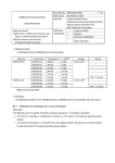
(A)
Table of Operating Precautions
µPD70F323x, µPD70323x
Rev.
No.
✓
✗
RankNote
Outline
K
E
1
AFCAN: Sleep Mode Wakeup
(Specification change notice)
✗
✗
2
Stand-by Mode Release
(Specification change notice)
✗
✗
3
Undefined Voltage Level on Analog ports
(Specification change notice)
✗
✗
:Not applicable
:Applicable
Note: The rank is indicated by the letter appearing at the 5th position from the left in the lot number, marked
on each product.
µPD70F323xA, µPD70323xA
Rev.
No.
RankNote
Outline
K
1
AFCAN: Sleep Mode Wakeup
(Specification change notice)
✗
2
Stand-by Mode Release
(Specification change notice)
✓
3
Undefined Voltage Level on Analog ports
(Specification change notice)
✗
✓ : Not applicable
✗ : Applicable
Note: The rank is indicated by the letter appearing at the 5th position from the left in the lot number, marked
on each product.
Customer Notification U18385EE6V0IF00
5
Operating Precautions for V850ES/Fx2
µPD70F323xB
Rev.
No.
RankNote
Outline
K
1
AFCAN: Sleep Mode Wakeup
(Specification change notice)
✗
2
Stand-by Mode Release
(Specification change notice)
✓
3
Undefined Voltage Level on Analog ports
(Specification change notice)
✓
✓ : Not applicable
✗ : Applicable
Note: The rank is indicated by the letter appearing at the 5th position from the left in the lot number, marked
on each product.
6
Customer Notification U18385EE6V0IF00
Operating Precautions for V850ES/Fx2
(B) Description of Operating Precautions
No. 1
AFCAN: Sleep Mode Wakeup
(Specification change notice)
1. Description
When the AFCAN macro is set into SLEEP mode, it can be waken up by CAN bus activity.
This waking up is asynchronous to the operation of the macro and the CPU. By configuration setting, a WAKEUP interrupt can be generated by the AFCAN macro on the wakeup event.
While the interrupt is generated asynchronously, the AFCAN macro may need another dominant
edge on the CAN bus, or software clearing of the SLEEP mode, in order to restart its synchronous
operation.
During the time, after the interrupt already has been indicated, and before the CAN macro has
restarted its synchronous operation, the registers of the AFCAN macro will not operate, because
the AFCAN macro still remains in SLEEP mode. This time we will refer to as “wakeup dead time”
in the following context.
To resolve from the wakeup dead time, software and/or hardware measures are required.
2. Exclusions
This Operating Precaution is only applicable to applications, which are fulfilling at least one of
the following three conditions:
• SLEEP Mode of AFCAN is used and the possibility to wake up AFCAN by CAN-Bus
events is given (see remark 1 below).
• During SLEEP mode of the AFCAN macro, a CAN-Bus wakeup condition occurs, while
the AFCAN macro is supplied with clock (see remark 2 below) and
- after waking up from SLEEP mode of the AFCAN macro, the application software does
not wait until the SLEEP mode is released by polling the CnCTRL (PSMODE) register,
before continuing operation with the AFCAN macro (see remark 3 below) and
- the CPU can reach instructions, where AFCAN registers are accessed while the
AFCAN macro is still in SLEEP mode, due to the missing waiting condition.
• During SLEEP mode of the AFCAN macro, a CAN-Bus wakeup condition occurs, while
the AFCAN macro is supplied with clock (see remark 2 below) and
- after waking up from SLEEP mode of the AFCAN macro, the CAN Bus Transceiver
generates a long-lasting or permanent dominant level to the CRXD input of the
AFCAN macro, instead of the propagated CAN-Bus level.
Remarks: 1. If the CAN-Bus Transceiver does not propagate the CAN-Bus signal, while the
AFCAN macro is in SLEEP mode, and also does not forward a wakeup signal to
CRXD, this Operating Precaution is not applicable.
2. The clock supply to the AFCAN macro can be stopped, depending on the features
of the device, and the system design of the application. If the clock supply to the
AFCAN macro is stopped, while a wakeup condition occurs, this Operating Precaution is not applicable.
3. The maximum waiting time for this loop can be up to 10 bits of the CAN-Bus
Baudrate.
Waiting while retrying to clear CnINTS (Bit 5) can be used alternatively.
All other applications are not affected by this Operating Precaution.
Customer Notification U18385EE6V0IF00
7
Operating Precautions for V850ES/Fx2
No. 1
AFCAN: Sleep Mode Wakeup
(Specification change notice)
3. Application Dependency
3.1 Overview
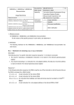
The following flowchart illustrates, how and whether additional measures have to be taken in software, to avoid the wakeup dead time.
Figure: Additional Measures in case AFCAN clock is active when waking up
AFCAN sleep mode
(In case AFCAN Clock is disabled)
Releasing AFCAN sleep mode
by CAN bus activity
Releasing AFCAN sleep mode
by user
(In case AFCAN Clock is active)
Releasing AFCAN sleep mode
by CAN bus activity
After detected dominant edge
PSMODE0 = 0
CINTS5 = 1
After detected dominant edge
PSMODE0 = 0/1
CINTS5 = 1
Clear PSMODE0 bit:
Additional Measure
Clear PSMODE0 bit
Clear CINTS5 bit
Clear CINTS5 bit
END
3.2 Not affected Applications
3.2.1 Applications not using SLEEP mode
If SLEEP mode is not used, this Operating Precaution is not applicable.
3.2.2 Applications waking up from SLEEP mode by User Request only
If there is no condition, when SLEEP mode can be left by CAN-Bus activity, but only on User
Request (by clearing the PSMODE flag by software), this Operating Precaution is not applicable.
3.2.3 Applications using a CPU Power Save Mode
If the clock to the AFCAN macro is disabled, while it is waken up from SLEEP mode, this operating precaution is not applicable.
This means, if the user selects a power save mode of the target device, which switches off the
clock of the AFCAN macro, immediately after it had been set into SLEEP mode, like the CPU
STOP mode, the precaution needs not to be considered.
This is associated with the software improvement hints below.
8
Customer Notification U18385EE6V0IF00
Operating Precautions for V850ES/Fx2
No. 1
AFCAN: Sleep Mode Wakeup
(Specification change notice)
3.3 Affected Applications
3.3.1 Applications not waiting until SLEEP mode is left
If bus transceivers are used in conjunction with AFCAN, which will propagate the CAN bus signal
to AFCAN permanently (not switched off or not in power saving modes), or, if bus transceivers are
used in conjunction with AFCAN, which will propagate the unmodified CAN-Bus signal when waking up from a power save mode, the wakeup dead time lasts from the first recessive-to-dominant
edge of the CAN-Bus signal, which generates the wake-up, until the next recessive-to-dominant
edge of the CAN-Bus signal.
The worst case (maximum length) of the wakeup dead time, is given by the CAN bus speed and
the rule of the CAN bus about the frequency of recessive-to-dominant edges. Given by the stuffing rule, at least every 10 bits, a recessive-to-dominant edge must occur.
If during the wakeup dead time, the CPU waits until the SLEEP mode is indicated to be cleared
(either by polling the PSMODE flag, or by retrying to clear CnINTS[5]), this operating precaution is not applicable. In this case, the improvement hint according to 4.2.2 is followed implicitly.
If during the wakeup dead time, the CPU does not perform any access to the AFCAN macro in
any case, this operating precaution is not applicable.
3.3.2 Applications using Bus Transceivers generating long-lasting dominant CAN-Bus Signals
If bus transceivers are used in conjunction with AFCAN, which generate a permanent or long-lasting dominant level when waking up from a power save mode, the operating precaution must be
considered in any case.
In this case, the wakeup dead time lasts from the first recessive-to-dominant edge of the CAN bus
signal, which generates the wake-up, until the next recessive-to-dominant edge of the CAN bus
signal, depending on the behaviour of the CAN bus transceiver.
If no further dominant edge on the CAN bus occurs (in case of some CAN transceivers, which
only provide one single edge on waking up), the time until SLEEP mode is left may become endless. Therefore, the waking up procedure of AFCAN regarding software, must be adjusted according to 4.1.1.
4. Software Improvement Hints
4.1 Recommended WAKEUP Handling by Software
4.1.1 Clearing the SLEEP Mode by Software
Within the WAKEUP interrupt routine, before accessing any other register or area of AFCAN, the
SLEEP mode can be canceled by software, followed by a clearance of the WAKEUP interrupt
flag.
Doing so, the AFCAN macro will start its synchronous operation right after these accesses.
In the following C-code example, replace the objects in “<>” brackets by the hardware locations
within your implementation. Use the appropriate access types, as described in the User’s Manual.
WAKEUP INTERRUPT VECTOR -->
<CnCTRL_PSMODE> = 0;
/* Clear SLEEP Mode */
<CnINTS_CINTS5> = 1;
/* Clear INTS5
*/
...
/* following other parts of interrupt routine */
...
Remark:
Clearing INTS5 is required to get another WAKEUP interrupt anyway, by specification.
Customer Notification U18385EE6V0IF00
9
Operating Precautions for V850ES/Fx2
No. 1
AFCAN: Sleep Mode Wakeup
(Specification change notice)
4.2 Other WAKEUP Handling Hints
4.2.1 Switching off the Clock Supply to AFCAN, while in SLEEP Mode
If the clock supply to the AFCAN macro is stopped, while it is in SLEEP mode, the synchronisation of the WAKEUP works without any restriction. To achieve this, the documentation of clock
controlling unit of the target device should be consulted. Usually this is performed by setting the
STOP mode of the CPU of the target device.
However, the user has to consider, that there must not be any WAKEUP condition (dominant level
on the CAN-Bus), while the software is executing between setting SLEEP mode and stopping the
AFCAN clock.
4.2.2 Using a Waiting Loop within the WAKEUP interrupt routine
Within the WAKEUP interrupt routine, create a waiting loop, which tests the capability of clearing
the WAKEUP interrupt flag within AFCAN, by checking the actual power save mode.
In the following C-code example, replace the objects in “<>” brackets by the hardware locations
within your implementation. Use the appropriate access types, as described in the User’s Manual.
do
{
AFCAN_SleepStatus = <CnCTRL_PSMODE>
if( AFCAN_SleepStatus != 0 )
{
/* macro is still in SLEEP mode (waiting for latency time) */
<CnINTS_CINTS5> = 1; /* repeated trying to clear CINTS5 */
}
} while( AFCAN_SleepStatus != 0 );
This improvement hint cannot be applied, if a CAN-Bus-Transceiver is attached to AFCAN,
which generates a permanent or long-lasting dominant level to the FCRXDn receive input pin, if a
wakeup condition occurs. Missing another dominant edge on the bus, the synchronisation will not
happen, and the loop could run endlessly.
4.2.3 Using INIT Mode instead of SLEEP Mode
In this case, the waking up by CAN-bus activity must be performed via another free external interrupt. The CAN receive signal must be distributed on the FCRXDn pin, and to another external
interrupt pin in parallel.
Using this external interrupt, the AFCAN macro can be restored into the previous operation mode.
This implementation will not use the SLEEP mode of AFCAN at all, and use the INIT mode
instead.
10
Customer Notification U18385EE6V0IF00
Operating Precautions for V850ES/Fx2
No. 2
Stand-by Mode Release
(Specification change notice)
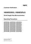
Description:
If a stand-by mode request and a wake-up event coincide with the same timing, the µC may enter
the power save mode in a way that the power save mode can be released by Reset (external or
internal) only.
This happens only if the stand-by mode request and the wake-up event occur within a timing window of 0.46 nsec width.
The term “stand-by mode” of the above description refers to all stand-by modes which are
selected by the Power Save Control Register (PSC).
The term “wake-up event“ of the above description refers to any event which is configured to
release the microcontroller from a stand-by mode. This can be any unmaskable or unmasked
maskable interrupt (internal or external) except reset.
Affected stand-by modes are:
- Idle1 Mode,
- Idle2 Mode,
- Sub-Idle Mode and
- Stop Mode
Not affected stand-by mode:
- Halt Mode
Please see the flowchart on the following page.
Customer Notification U18385EE6V0IF00
11
Operating Precautions for V850ES/Fx2
No. 2
Stand-by Mode Release
(Specification change notice)
Description (continued):
Please see the following flowchart to check if the described behaviour might be relevant for a particular application:
12
Customer Notification U18385EE6V0IF00
Operating Precautions for V850ES/Fx2
No. 3
Undefined Voltage Level on Analog ports
(Specification change notice)
Description:
An undefined voltage level in the range of GND to AVREF0 may be output on one of the analog
ports (ANIn NOTE) after power-on.
In case of utilizing as I/O port functions, the undefined voltage level may be seen continuously
until the next power-on.
The input or output port function may not operate as expected since the input voltage from external circuits or output voltage from the I/O port of this device may be altered due to this behaviour.
Depending on the supply voltage and the external circuitry a maximum input or output current of
11.8 mA can occur (e. g. in case of supply voltage = 5.5 V and external connection to GND).
NOTE:
n = 0 to 9 for V850ES/FE2
n = 0 to 11 for V850ES/FF2
n = 0 to 15 for V850ES/FG2
n = 0 to 23 for V850ES/FJ2
Workaround:
The described behaviour disappears when the ADC is enabled at least once after power-on.
Therefore the ADC should be enabled at least once even if the ADC is not used in the application.
The ADC is enabled by setting the ADA0CE bit of the ADA0M0 register to 1.
Customer Notification U18385EE6V0IF00
13
Operating Precautions for V850ES/Fx2
(C)
Valid Specification
Item
Date pulished
Document No.
Document Title
1
November 2005
U17830EE1V0UM00
V850ES/Fx2 Hardware (User’s Manual)
2
December 2005
U17830EE1V0X000
Errata Sheet for V850ES/Fx2 Hardware (User’s Manual)
3
November 2004
U17834EE1V0DS00
Data Sheet for V850ES/FE2
4
April 2006
U17833EE3V0DS00
Data Sheet for V850ES/FF2
5
November 2005
U17832EE1V0DS00
Data Sheet for V850ES/FG2
6
November 2005
U17831EE1V0DS00
Data Sheet for V850ES/FJ2
7
February 2010
U15943EJ4V0UM00
V850ES Architecture (User’s Manual)
14
Customer Notification U18385EE6V0IF00
Operating Precautions for V850ES/Fx2
(D) Revision History
Item
Date pulished
Document No.
Comment
1
August 2006
TPS-HE-B-2590
New List
2
October 2006
U18385EE3V0IF00
Added item 2, added No. 7 to section “Valid Specification”
3
December 2006
U18385EE3V1IF00
Added mask rank “E”
4
May 2007
U18385EE4V0IF00
Added µPD70F323xA, µPD70323xA
5
October 2008
U18385EE5V0IF00
Added item 3
6
March 2010
U18385EE6V0IF00
Added µPD70F323xB
Customer Notification U18385EE6V0IF00
15