1
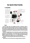
195Z
USER MANUAL
EXCELLENT CONTROL DEVICE WITH FULL FUNCTIONALITY
Thank you for choosing this keyboard controller.
Before attempting to connect or operate this product,
please read the instructions thoroughly and
save this manual for future reference.
AVP101_V1.2
IMPORTANT SAFEGURARD
CAUTION
RISK OF ELECTRIC SHOCK
CAUTION:
To reduce the risk of electric shock, do not expose this apparatus to rain or moisture.
Only operate this apparatus from the type of power source indicated on the label.
The company shall not be liable for any damages arising out of any improper use, even if we have been
advised of the possibility of such damages.
The lightning flash with arrowhead symbol, within an equilateral triangle, is intended to alert the
user to the presence of uninsulated “dangerous voltage” within the product’s enclosure that
may be of sufficient magnitude to constitute a risk of electric shock to persons.
This exclamation point within an equilateral triangle is intended to alert the user to the presence
of important operating and maintenance (servicing) instructions in the literature accompanying
the appliance.
ROHS Announcement
All lead-free products offered by the company comply with the requirements of the European
law on the Restriction of Hazardous Substances (RoHS) directive, which means our
manufacture processes and products are strictly “lead-free” and without the hazardous
substances cited in the directive.
The crossed-out wheeled bin mark symbolizes that within the European Union the product
must be collected separately at the product end-of-life. This applies to your product and any
peripherals marked with this symbol. Do not dispose of these products as unsorted municipal
waste.
CE Mark
This apparatus is manufactured to comply with the radio interference.
We reserve the right to make improvements to the documentation, software and firmware of its products without
notice. In order to provide users with better operation of this product, information in this manual is intended to be
accurate and reliable. However, we assume no responsibility for its use, nor for any infringements of rights of third
parties whom may result from its use. For the actual display & operation, please refer to your device in hand. Any
changes of this manual are subject to the actual product without further notification.
Firmware Version: 1.079L
~i~
TABLE OF CONTENTS
INTRODUCTION ..........................................................................................................................................................1
1. Overview .............................................................................................................................................................1
2. Features ..............................................................................................................................................................1
3. Specifications ......................................................................................................................................................1
4. Package Content.................................................................................................................................................2
CONNECTION AND SETUP ........................................................................................................................................3
1. General Connection ............................................................................................................................................3
2. Connectors on Rear Panel..................................................................................................................................3
a). Audio Out (AUDIO).......................................................................................................................................3
b). External I/O Port (EXTERNAL I/O)...............................................................................................................3
PIN Configuration...................................................................................................................................3
c). RS485 Port (DVR / P.T.Z) .............................................................................................................................4
Port Connection & System Mode Selection...........................................................................................4
d). LAN...............................................................................................................................................................4
e). Power Connector (DC 12V)..........................................................................................................................4
3. Speed Dome Camera Connection ......................................................................................................................5
a). Single Camera Connection...........................................................................................................................5
b). Parallel Connection With Two Or More Cameras.........................................................................................6
4. DVR Connection .................................................................................................................................................7
a). Single DVR Connection................................................................................................................................7
b). Parallel Connection With Two Or More DVRs..............................................................................................8
PARTS AND KEYS .....................................................................................................................................................10
1. Keypad Layout ..................................................................................................................................................10
2. LCD Display ......................................................................................................................................................10
3. Function of Each Key........................................................................................................................................11
a). Device Selection.........................................................................................................................................11
b). Device Control ............................................................................................................................................12
c). Lock ............................................................................................................................................................12
d). Joystick .......................................................................................................................................................12
e). General .......................................................................................................................................................12
Menu ....................................................................................................................................................12
Navigation ............................................................................................................................................12
+ / - .................................................................................................................................................12
Number Pad .........................................................................................................................................13
f). Camera Control ..........................................................................................................................................13
g). DVR Control ...............................................................................................................................................14
Audio Channel Selection Keys.............................................................................................................14
Playback Keys......................................................................................................................................14
Display Mode Selection Keys ..............................................................................................................14
~ii~
h). Shortcut Keys .............................................................................................................................................15
PROGRAMMING ........................................................................................................................................................16
1. Menu Tree .........................................................................................................................................................16
2. Menu List...........................................................................................................................................................17
a). System........................................................................................................................................................17
Set Password .......................................................................................................................................17
Set Network..........................................................................................................................................17
Set Hot Key ..........................................................................................................................................17
Set Host ID...........................................................................................................................................18
Set Mode..............................................................................................................................................18
b). Camera .......................................................................................................................................................19
Select Camera ID.................................................................................................................................19
Set Baud Rate......................................................................................................................................19
Set Mode..............................................................................................................................................19
c). DVR ............................................................................................................................................................20
Select DVR ID ......................................................................................................................................20
Set Baud Rate......................................................................................................................................20
Set Mode..............................................................................................................................................20
3. Firmware Upgrade ............................................................................................................................................21
~iii~
LIST OF TABLES
Table 1: Keyboard controller specifications ..................................................................................................................1
Table 2: PIN configuration.............................................................................................................................................4
Table 3: RS485 port connection and system mode selection.......................................................................................4
Table 4: Audio channel switch.....................................................................................................................................14
Table 5: Shortcut Keys................................................................................................................................................15
Table 6: Touch panel options ......................................................................................................................................16
Table 7: Keys for programming...................................................................................................................................16
LIST OF FIGURES
Figure 1: Example of keyboard controller connection -- connect up to 64 devices......................................................3
Figure 2: Connectors on the rear side ..........................................................................................................................3
Figure 3: Solder side of this product’s supplied 9-pin D-Sub connector.......................................................................4
Figure 4: RJ11 Line.......................................................................................................................................................5
Figure 5: Example of RS485-A and RS485-B wires .....................................................................................................5
Figure 6: RJ-11 Line......................................................................................................................................................7
Figure 7: Solder side of the DVR’s supplied D-Sub connector.....................................................................................7
Figure 8: RS485 Port ....................................................................................................................................................7
Figure 9: Example of Parallel Connection with Two DVRs...........................................................................................8
Figure 10: Controller Keypad Layout ..........................................................................................................................10
Figure 11: LED Display & Touch Panel.......................................................................................................................10
Figure 12: Key.............................................................................................................................................................11
Figure 13: Conf ...........................................................................................................................................................16
Figure 14: System.......................................................................................................................................................17
Figure 15: Password Setting.......................................................................................................................................17
Figure 16: Example - IP Address Setting....................................................................................................................17
Figure 17: Hot Key ......................................................................................................................................................18
Figure 18: Host ID.......................................................................................................................................................18
Figure 19: Mode..........................................................................................................................................................18
Figure 20: Buzzer........................................................................................................................................................18
Figure 21: Set 311 ID ..................................................................................................................................................18
Figure 22: Camera ......................................................................................................................................................19
Figure 23: Camera ID .................................................................................................................................................19
Figure 24: Camera Baud Rate....................................................................................................................................19
Figure 25: Camera mode............................................................................................................................................19
Figure 26: DVR ...........................................................................................................................................................20
Figure 27: DVR ID.......................................................................................................................................................20
Figure 28: DVR Baud Rate .........................................................................................................................................20
Figure 29: DVR Mode .................................................................................................................................................20
~iv~
INTRODUCTION
1. Overview
This product is designed for use with all our speed dome cameras & DVRs. It can serve as a control console to
manage your surveillance system, and is able to control up to 64 devices with the convenient 3D joystick and
functional keypad design. Accurate control of the pan / tilt / zoom movement for a speed dome camera becomes
easy, and you can operate other devices via this product conveniently.
2. Features
Controls up to 64 devices through one keyboard controller
(Devices such as the PTZ camera & DVR…etc.)
User-friendly button placement & LCD touch panel (128 * 64 pixels) for easy operation
Network upgrade available for future scalability
Supports our own protocol, PELCO-D and PELCO-P
Password protection to prevent unauthorized users
Built-in microphone for broadcast function
3. Specifications
Keyboard Controller
Device Control
PTZ camera & DVR…etc.
Remote Control
RS-485
Protocols
Our own protocol / PELCO-D / PELCO-P
Baud Rate
2400 ~ 57600
LCD Display
128 * 64 pixels
Ethernet Port
10/100 Base-T
Serial Port
9-Pin D-Sub
Input Voltage
DC12V
Power Consumption
< 2W
Operating Temperature
0°C ~ 40°C
Operating Humidity
< 95%
Dimension
380(W) mm x 180(H) mm x 95(D) mm
* The specifications are subject to change without notice.
Table 1: Keyboard controller specifications
~1~
4. Package Content
Please make sure you have the following items in your sales package:
Keyboard Controller x 1
Stylus x 1
Adapter x 1
User Manual x 1
9-pin D-Sub Connector
and its accessories x 1
~2~
CONNECTION AND SETUP
1. General Connection
Figure 1: Example of keyboard controller connection -- connect up to 64 devices
2. Connectors on Rear Panel
AUDIO
EXTERNAL I/O
DVR P.T.Z
LAN
DC 12V
Figure 2: Connectors on the rear side
a). Audio Out (AUDIO)
Audio-out connector, used to connect to an audio device, such as a speaker.
NOTE This function will be ready in the future.
b). External I/O Port (EXTERNAL I/O)
RS-232 port, used to connect to an external alarm device with the supplied 9-pin D-Sub connector.
PIN Configuration
Only PIN 1, 3 and 5 are functional. Connect to PIN 1 & 3, or PIN 1 & 5 depending on your situation.
~3~
PIN
FUNCTION
DESCRIPTION
1
COM.
(COMMON)
COM. is used with N.O. or N.C. for
the N.O. or N.C. circuit to take
effects.
For the N.O. or N.C. connection,
and the alarm-triggered criteria, see
the description below.
3
N.O.
When N.O. is connected, an alarm
(NORMALLY is triggered by a momentary short
OPEN)
in a normally-open (N.O.) circuit.
5
N.C.
When N.C. is connected, an alarm
(NORMALLY is triggered by a momentary break
CLOSED)
in a normally-closed (N.C.) circuit.
Figure 3: Solder side of this product’s
supplied 9-pin D-Sub connector
Table 2: PIN configuration
c). RS485 Port (DVR / P.T.Z)
Two RS485 ports, used to connect to a speed dome camera or DVR.
Port Connection & System Mode Selection
Device
One DVR and
--
one camera
A DVR
Two DVRs or
more
or more
Mode*
DVR: DVR
M-1
Camera: P.T.Z
--
DVR
M-1
Parallel**
DVR
M-1
DVR
M-2
P.T.Z
Both M-1 and M-2 are OK
--
DVR & P.T.Z
M-2
Parallel
DVR
M-2
Parallel
P.T.Z
Both M-1 and M-2 are OK
One camera
Two cameras
Port
Connection Method
--
Table 3: RS485 port connection and system mode selection
d). LAN
Connect to the local area network (LAN) or Internet through a network cable with RJ-45 connectors. This
port can be used only for firmware upgrade, and extend the scalability of this product.
For details, please see “Firmware Upgrade” at page 21
e). Power Connector (DC 12V)
Connect to the supplied adapter.
*
**
To select the mode, click “Conf” on the touch panel, and go to “Mode”. For details, please see “Set Mode” at page 18.
For parallel connection details, please see “Parallel Connection With Two Or More Cameras” at page 6, and “Parallel Connection With Two Or
More DVRs” at page 8.
~4~
3. Speed Dome Camera Connection
There are only two RS485 ports (DVR / P.T.Z) for camera connection. For the normal camera connection, please
see “Single Camera Connection” at page 5. For the parallel connection with two or more cameras, please see
“Parallel Connection With Two Or More Cameras” at page 6.
NOTE: You need a RJ11 line to connect this product and a speed dome camera. Different RJ11
connector may have different RS485-A & RS485-B wire layout, so the connection might be
different. If you cannot control the camera after connection, please reverse the wire
connection with the camera.
a). Single Camera Connection
Step1: Before connecting this product to your speed
dome camera, finish the camera connection and
setup first as described in your camera’s user
manual.
Step2: Get a RJ11 line with the proper length for your
connection.
Step3: Remove one end of the insulating coating of the
RJ11 line to reveal four wires. Find the RS485-A
and the RS485-B wires, and remove the
Figure 4: RJ11 Line
insulating coating to reveal the naked wires for
further connection. For example, in Figure 4, the
RS485-A wire is the red one, and the RS485-B
wire is the green one.
NOTE: The RJ11 line is not supplied in the sales
package.
Step4: Find the RS485-A and RS485-B wires from your
speed dome camera (Figure 5). For details,
please check your camera’s user manual.
Step 5: Twist the red and green wires of the RJ11 line to
the corresponding wires of your camera.
Figure 5: Example of
RS485-A and RS485-B wires
Take Figure 4 & 5 as an example, the connection
will be as follows:
RJ11 Line
Camera
Red wire (RS485-A)
Brown wire
Green wire (RS485-B)
Orange wire
Step6: To protect the naked wires, use the insulation tape to cover on the twisted wires.
Step7: Connect the RJ11 connector to the RS485 port “DVR” and / or “P.T.Z” on the rear side of this
product depending on your connection needs. For details, please see “Table 3: RS485 port
connection and system mode selection” at page 4.
~5~
Step8: Click “Conf” on the touch panel, and click the system icon and camera icon to make related settings.
● System (See “System” at page 17 for details)
MODE
: Select M-1 or M-2 depending on your connection needs.
For details, please see “Table 3: RS485 port connection and system mode
selection” at page 4 for details
● Camera (See “Camera” at page 19 for details)
RATE
: Check and select the baud rate the same as the connected speed dome camera
is used.
MODE
: Choose the proper camera protocol depending on the camera type, AVP321 /
AVP311 / PELCO-D / PELCO-P.
ID
: Assign a unique ID. This ID is important for this product to identity the camera you
want to control if two or more speed dome cameras are connected.
b). Parallel Connection With Two Or More Cameras
Step1: Before connecting this product to two or more speed dome cameras, finish the camera connection and
setup first as described in your camera’s user manual.
Step2: Get a RJ11 line with the proper length for your connection.
Step3: Remove one end of the insulating coating of the RJ11 line to find the RS485-A and the RS485-B wires,
and remove the insulating coating to reveal the naked wires for further connection. For example, in
Figure 4, the RS485-A wire is the red one, and the RS485-B wire is the green one.
NOTE: The RJ11 line is not supplied in the sales package.
Step4: Find the RS485-A and RS485-B wires (Figure 5) from all your speed dome cameras. For details, please
check your camera’s user manual.
Step 5: Twist the red wire of the RJ11 line and the RS485-A wires of all the cameras together. Then, twist the
green wire of the RJ11 line and the RS485-B wires of all the cameras together.
Step6: To protect the naked wires, use the insulation tape to cover on the twisted wires.
Step7: Connect the RJ11 connector to the RS485 port “DVR” or “P.T.Z” on the rear side of this product
depending on your connection needs. For details, please see “Table 3: RS485 port connection and
system mode selection” at page 4 for details.
Step8: Click “Conf” on the touch panel, and click the system icon and camera icon to make related settings.
● System (See “System” at page 17 for details)
MODE
: Select M-1 or M-2 depending on your connection needs.
For details, please see “Table 3: RS485 port connection and system mode
selection” at page 4 for details
NET WORK
: Check if this product is under the same domain as the connected speed dome
camera.
● Camera (See “Camera” at page 19 for details)
RATE
: Check and select the baud rate the same as the connected speed dome camera
is used.
MODE
: Choose the proper camera protocol depending on the camera type, AVP321 /
AVP311 / PELCO-D / PELCO-P.
ID
: Assign a unique ID. This ID is important for this product to identity the camera you
want to control if two or more speed dome cameras are connected. You need to
set different ID for each connected camera, or this product will not be able to
control it.
~6~
4. DVR Connection
There is only one RS485 port (DVR) available for DVR connection. For the single DVR connection, please see
“Single DVR Connection” at page 7. For the parallel connection with two or more DVRs, please see “Parallel
Connection With Two Or More DVRs” at page 8.
NOTE: You need a RJ11 line to connect this product and a DVR. Different RJ11 connector may have
different RS485-A & RS485-B wire layout, so the connection might be different. If you
cannot control the DVR after connection, please reverse the wire connection with the DVR.
a). Single DVR Connection
Step1: Before connecting this product to your
DVR, finish your DVR connection and
setup first as described in your DVR’s
user manual.
Step2: Get a RJ11 line with the proper length to
your connection.
Step3: Remove one end of the insulating coating
of the RJ11 line to find the RS485-A and
the RS485-B wires, and remove the
insulating coating to reveal the naked
wires for further connection. For example,
in Figure 6, the RS485-A wire is the red
one, and the RS485-B wire is the green
one.
Figure 6: RJ-11 Line
Solder Side of
15-pin D-Sub connector
RS485-A: PIN11 / RS485-B: PIN10
8
15 14
16
NOTE: The RJ11 line is not supplied in the
sales package.
DVR D-Sub Connector
Red wire
15PIN Connector: PIN11
(RS485-A)
25PIN Connector: PIN11
Green wire
15PIN Connector: PIN10
(RS485-B)
25PIN Connector: PIN23
6
5
13
4
12
3
11
1
2
10 9
17
Solder Side of
25-pin D-Sub connector
Step4: Solder the red and green wires of the
RJ11 line to the corresponding pins of the
D-Sub connector supplied with the
connected DVR (Figure 7), or the RS485
port on the DVR rear panel (Figure 8).
RJ11 Line
7
RS485-A: PIN11 / RS485-B: PIN23
13 12 11 10 9
8
7
6
5
4
3
2 1
25 24 23 22 21 20 19 18 17 16 15 14
Figure 7: Solder side of the DVR’s
supplied D-Sub connector
2: RS485-A
3: RS485-B
Table 4: RJ11 line to DVR Connection
Figure 8: RS485 Port
NOTE: The actual corresponded RS485-A/B pin number, please refer to your DVR user manual or
consult your installer.
Step5: To protect the naked wires, use the insulation tape to cover on the twisted wires.
Step6: Insert the connector to the DVR’s external I/O port.
~7~
Step7: Connect the RJ11 connector to the “DVR” port on the rear panel of this product.
Step8: Click “Conf” on the touch panel, and click the system icon and DVR icon to make related settings.
● System (See “System” at page 17 for details)
MODE
: Select M-1.
● DVR (See “DVR” at page 20 for details)
RATE
: Check and select the baud rate the same as the connected DVR is used.
MODE
: Choose the proper DVR protocol depending on the DVR type, DVR-16
(16CH) / DVR-8 (8CH) / DVR-4 (4CH).
ID
: Assign a unique ID. This ID is important for this product to identity the DVR
you want to control.
b). Parallel Connection With Two Or More DVRs
Step1: Before connecting this product to your DVR, finish your DVR connection and setup first as described in
your DVR’s user manual.
Step2: Get enough RJ11 lines with the proper length for your connection. If you want to connect two DVRs,
three RJ11 lines will be needed; if you want to connect three DVRs, four RJ11 lines will be needed, etc.
The following description will take two-DVR connection as an example.
Step3: Remove one end of the insulating coating of the RJ11 line to find the RS485-A and the RS485-B wires,
and remove the insulating coating to reveal the naked wires for further connection. For example, in
Figure 6, the RS485-A wire is the red one, and the RS485-B wire is the green one.
NOTE: The RJ11 line is not supplied in the sales package.
Step4: Solder the red and green wires of the RJ11 line to the corresponding pins of the D-Sub connector
supplied with the connected DVR (Figure 7).
Step5: Twist the red wire of the RJ11 line and the RS485-A wires of the two DVRs together. Then, twist the
green wire of the RJ11 line and the RS485-B wires of the two DVRs together.
AUDIO
EXTERNAL I/O
DVR P.T.Z
LAN
DC 12V
RJ11 Jack
A
B
A
13 12 11 10 9
8
7
6
5
4
3
RS485-A (Red)
RS485-B (Green)
A B
B
8
2 1
7
15 14
16
25 24 23 22 21 20 19 18 17 16 15 14
25-pin D-Sub connector
6
5
4
3
2
13 12 11 10
1
9
17
15-pin D-Sub connector
PIN11: RS485-A
PIN23: RS485-B
PIN11: RS485-A
PIN10: RS485-B
Figure 9: Example of Parallel Connection with Two DVRs
NOTE: The actual corresponded RS485-A/B pin number, please refer to your DVR user manual or
consult your installer.
~8~
Step6: To protect the naked wires, use the insulation tape to cover on the twisted wires.
Step7: Insert the D-Sub connector to the DVR’s external I/O port.
Step8: Connect the RJ11 connector to the port “DVR” on the rear panel of this product.
Step9: Click “Conf” on the touch panel, and click the system icon and DVR icon to make related settings.
● System (See “System” at page 17 for details)
MODE
: Select M-1.
● DVR (See “DVR” at page 20 for details)
RATE
: Check and select the baud rate the same as the connected DVR is used.
MODE
: Choose the proper DVR protocol depending on the DVR type, DVR-16
(16CH) / DVR-8 (8CH) / DVR-4 (4CH).
ID
: Assign a unique ID. This ID is important for this product to identity the DVR
you want to control. You need to set different ID for each connected DVR,
or this product will not be able to control it.
~9~
PARTS AND KEYS
This chapter describes the keypad layout, and the function or usage of each key and the combination keys.
1. Keypad Layout
Figure 9 shows the keypad layout of this product, from which you can briefly check the functions of this product.
For details of each key function, please see “Function of Each Key” at page 11.
Figure 10: Controller Keypad Layout
2. LCD Display
Device LED
: Indicate which device this product is controlling right
now.
The icons from left to right represent the speed dome
camera, door access system, lighting system,
microphone, and DVR respectively.
To switch between each device, please see “Device
Selection” at page 11 for details.
Figure 11: LED Display & Touch Panel
~10~
Touch Panel : In the standby mode, touch the panel or press any key
to show the latest camera ID and DVR ID this product
controlled.
To control the connected device:
With the supplied stylus, click the device icon (PTZ
camera or DVR), and key in the ID number of the
device you want to control by clicking “+” or “-” on the
touch panel, or directly entering the ID with the
number pad (See “Number Pad” at page 13).
To configure the connected device:
With the supplied stylus, click “Conf” on the touch
panel, and select the device you want to configure
(See the chapter “PROGRAMMING” at page 16).
To set the hot key operation for the PTZ camera:
With the supplied stylus, click the camera icon, and
click “Key” on the touch panel to set the PTZ camera,
by clicking “+” or “-” on the touch panel, or directly
ESC
- +
entering the ID with the number pad (See “Number
Pad” at page 13), for the following functions:
HOME
: Go to the home position.
GOTO
: Assign the preset point when the
Figure 12: Key
corresponding function key is pressed.
SEQ
: Assign the sequence group when the
corresponding function key is pressed.
AUTO PAN : Enable the camera panning function.
3. Function of Each Key
a). Device Selection
Choose from the device selection keys
based on the connected device. The keys
on the right hand side represent the
*Access control, lighting system & microphone support will be
ready soon.
devices this product can control: speed
dome camera (
control (
), door access
), lighting system (
microphone (
) and DVR (
),
).
~11~
b). Device Control
This key set is designed to use with the control of the door access
(
), lighting system (
) and microphone (
). Press ON / OFF to
turn the device on / off.
This function will be ready in the future.
c). Lock
Press this key to lock the keypad, and press again to unlock by
entering the unlock password with the number pad.
To set the password, please see “Set Password” at page 17.
d). Joystick
Movement
Camera Control
Tilt up
Tilt down
Tilt left
Tilt right
Turn clockwise
Turn counter-clockwise
Move the camera up
Move the camera down
Move the camera left
Move the camera right
Zoom In
Zoom Out
e). General
NOTE: The actual operation varies depending on the device you switch to.
Menu
Press this key to show the main menu of the connected device,
and press again to go to the upper level of the menu list, or exit
the menu.
Navigation
Press
/
/
/
to move the cursor or
highlight up / down / left / right. To enter or confirm your
selection, press
(Enter).
+ / -
Press to switch the channel.
~12~
Number Pad
0 ~ 9 : Used to enter the camera ID, DVR ID, channel number,
password, etc.
: Confirm your key-in.
ESC : Clear your key-in / escape the channel sequence
mode.
f). Camera Control
Press
device selection key, or click the speed dome camera icon on the touch panel with the
supplied stylus to switch to the speed dome camera mode, and you can control the following function keys
and perform certain functions by some certain keystroke combinations:
NOTE: You can also use the camera control keys “FOCUS”, “
device is switched to
.
F1 / F2 / F3 / F4 : Operate the function you assigned in the “HOT
KEY” menu. There are 5 options available:
HOME, GOTO, SEQ, AUTO PAN and NONE.
For details, please see “Set Hot Key” at page
17.
Or,
Press with
to enable the shortcut key
function for showing ID, clearing ID, hiding ID,
or showing the firmware version. For details,
please see “Shortcut Keys” at page 15.
FOCUS
: Adjust the focal length.
: Zoom out / in.
TRACK
: Press to start tracking, and press again to quit
and return to the live view.
STOP : Press to stop the PTZ cruising.
~13~
”, “TRACK” and “STOP” when the
g). DVR Control
Press
device selection key, or click the DVR icon on the touch panel with the supplied stylus to
switch to the DVR mode, and you can control the following functions:
NOTE: You can also use the camera control keys “FOCUS”, “
device is switched to
.
Audio Channel Selection Keys
Press “NEXT” or “LAST” to choose the next / previous audio
channel to hear the live sound (in the live mode) or the
recorded sound (in the playback mode).
For example, if the connected DVR supports 4 audio channels:
Mode
Live Mode
Playback Mode
Selection
AUDIO OFF
AUDIO OFF
AUDIO 1 (L)
AUDIO 1 (P)
AUDIO 2 (L)
AUDIO 2 (P)
AUDIO 3 (L)
AUDIO 3 (P)
AUDIO 4 (L)
AUDIO 4 (P)
Table 4: Audio channel switch
Playback Keys
: Press to open the search list in which you can find the
recorded events and play the corresponding video clip.
Select one event from this list by using the navigation
keys, and press to play the video clip.
: Press to play the selected video clip.
: Press to fast-forward the video clip, from 4X to 32X.
: Press to fast-rewind the video clip, from 4X to 32X.
: Press to pause the video play.
: Press to stop the video play and go back to the live view.
Display Mode Selection Keys
: Press to display a single channel.
: Press to display the 4-cut view.
: Press to display the 8-cut view.
: Press to display the 9-cut view.
: Press to display the 16-cut view.
: Press to display each channel one by one.
~14~
”, “TRACK” and “STOP” when the
h). Shortcut Keys
Press and hold
, and press F1, F2, F3, F4 and
respectively to quickly perform different
functions as follows:
Key Combination
and F1
Functions
Description
This keystroke combination will show the camera
Show Camera ID
ID display on the monitor if the ID is hided.
This keystroke combination will clear the camera
and F2.
Clear Camera ID
ID information saved in the camera, and restore to
the default setting (01).
This keystroke combination will hide the camera ID
and F3
display on the monitor. To show the ID again, press
Hide Camera ID
and F1.
and F4
Show Firmware Version
This keystroke combination will show the current
of this Product
firmware version of this product for your reference.
Reset Default of this
and
Product
This keystroke combination enables the reset of
this product to the factory settings. Then, it will
prompt you to shut down and power up again.
Table 5: Shortcut Keys
~15~
PROGRAMMING
Click “Conf” on the touch panel with the supplied stylus to go the
device selection screen as shown in Figure 11, and you can configure
DVR
the controller system, connected speed dome camera(s), and
connected DVR(s).
ESC
Directly use the supplied stylus to touch the available options for
setting change (Table 6), or use the keypad (Table 7) to change the
setting.
Option or Action
Operation
+ / -
Click to set the digits, such as the host ID
///
Click to move the highlight up / down / left / right
ESC
Click to go to the previous menu level
Double-click
Double click to change the setting
Table 6: Touch panel options
Key
Function
Nagivation
Number Pad
/
/
/
to move between each selection
Number 1 ~ 9 to key in the digits, such as the host ID
to confirm your selection or key-in
ESC to clear your key-in
Table 7: Keys for programming
1. Menu Tree
NET WORK...
IP...
HOT KEY...
HOST ID
Gateway...
MODE
BUZZER
SET 311 ID
ID
CONF
RATE
MODE
ID
RATE
MODE
~16~
Figure 13: Conf
2. Menu List
a). System
Select the left icon to go to the system configuration screen. In this
menu list, you can set the password to unlock this product, set the
DVR
host ID, turn on/off the buzzer, select the mode, and set the
network.
ESC
Figure 14: System
Set Password
Set the password for the keylock function. When the keypad is locked, press
, and enter the
password you set here to unlock the keypad.
Select “PASSWORD…”. Enter the old password first (4 digits), and enter the new password.
The default password is 0000.
ESC
- +
Figure 15: Password Setting
Set Network
Select “NET IP…” to set the IP address, subnet mask and gateway of this product. Move to the item you
want to set and make settings.
The default settings are as follows:
IP Address
: 192.168.1.90
Subnet Mask
: 255.255.255.000
Gateway
: 192.168.1.254
Set IP Address
ESC
- +
ESC
- +
ESC
Figure 16: Example - IP Address Setting
Set Hot Key
Select “HOT KEY…” to assign one of the four functions, “HOME”, “GOTO”, “SEQ”, “AUTO PAN” to the
hot key F1, F2, F3 or F4, or disable the key function with the option “NONE”.
HOME
: Go to the home position.
GOTO
: Go to the preset point you set in “Key” (See “LCD Display” at page 10).
SEQ
: Enable the cruising function with the sequence group you specified in “Key” (See “LCD
Display” at page 10).
AUTO PAN : Enable the camera panning function.
NONE
: Disable the hot key function.
~17~
ESC
- +
ESC
- +
Figure 17: Hot Key
Set Host ID
Set the ID of this product when the connected device is also
connected to other device(s). The connected device needs this
ID to identify this product.
Select “HOST ID”, use the number pad to assign and enter an
ID for this product, and press ” “ to confirm.
ESC
- +
Figure 18: Host ID
The default setting is 00.
Set Mode
Select “MODE”, and select “M-1” or “M-2” depending on the
devices you’re connected. For details, please see “Table 3:
RS485 port connection and system mode selection” at page 4.
ESC
The default setting is M-1.
- +
Figure 19: Mode
Set Buzzer
Select “Buzzer”, and click to enable (ON) or disable (OFF)
the buzzer of the key-press.
The default setting is ON.
ESC
- +
Figure 20: Buzzer
Set 311 ID (only for AVP311)
Select “Set 311 ID”, and click to modify the new ID
depending on the device you connected.
The default setting is 000.
1. Enter the old ID.
- +
2. Enter the new ID.
3. Press “”.
ESC
Figure 21: Set 311 ID
4. Click “ESC” as many as needed to return to the main
menu.
5. Revise the ID of the camera to the new ID.
~18~
b). Camera
When this product is connected to a speed dome camera,
go to this menu list to set the baud rate, mode and ID of the
DVR
connected camera for the camera control to take effect.
Each camera must be assigned a unique ID, and the baud rate
and mode settings must be chosen correctly for the camera control
to work properly. For details, please check the description below.
Figure 22: Camera
Select Camera ID
Select the ID of the connected speed dome camera to show
the related setting for the camera ID, and make changes when
necessary.
Select “ID”, use the number pad to assign and enter an ID for
the camera, and press ” “ to confirm.
The default setting is 00.
- +
ESC
Figure 23: Camera ID
Set Baud Rate
Select “RATE”, and click to set the baud rate for the connected
camera. The options are: 2400 / 4800 / 9600 / 19200 / 38400 /
57600.
The default setting is 2400.
- +
Note: The setting here must be the same as the setting
in the connected speed dome camera for the
control of the camera to work properly.
ESC
Figure 24: Camera Baud Rate
Set Mode
Select “MODE”, and click to set the appropriate protocol for the
connected speed dome camera. The options are: AVP321 /
AVP311 / PELCO –D / PELCO-P.
The default setting is AVP321.
- +
ESC
Figure 25: Camera mode
~19~
c). DVR
When this product is connected to a DVR, go to this menu list to
set the baud rate, mode and ID of the connected DVR for the DVR
DVR
control to take effect.
Each DVR must be assigned a unique ID, and the baud rate and
mode settings must be chosen correctly for the DVR control to
work properly. For details, please check the description below.
ESC
Figure 26: DVR
Select DVR ID
Select the ID of the connected DVR to show the related setting
for the DVR ID, and make changes when necessary.
Select “ID”, use the number pad to assign and enter an ID for
the camera, and press ” “ to confirm.
- +
ESC
The default setting is 00.
Figure 27: DVR ID
Set Baud Rate
Select “RATE”, and click to set the baud rate for the connected
DVR. The options are: 2400 / 4800 / 9600 / 19200 / 38400 /
57600.
The default setting is 2400.
- +
NOTE: The setting here must be the same as the setting in
the DVR system configuration for the control of the
DVR to work properly.
ESC
Figure 28: DVR Baud Rate
Set Mode
Select “MODE”, and click to set the appropriate protocol for the
connected DVR. The options are: DVR-16 / DVR-8 / DVR-4
(16CH / 8CH / 4CH).
The default setting is DVR-16.
- +
ESC
Figure 29: DVR Mode
~20~
3. Firmware Upgrade
NOTE: For the firmware upgrade files, please consult your installer to get the latest version.
1). Connect this product to your PC/NB via a RJ-45 network cable. The default IP address is “192.168.1.90.” Set
your PC’s IP address as “192.168.1.xx” (1~255, except 90) in order to make the PC and this product under the
same domain.
2)
Double click the firmware icon on your PC/NB,
3). Make sure the IP Address correspond to this product. The default IP is “192.168.1.90”
Click Upgrade to continue. The product starts Erasing.
DVR
000
000
Erasing
Meanwhile, your PC/NB and the LCD of this product shows the update percentage.
DVR
000
000
45 Percent
4). When upgrade is complete, a window pops up. Please wait for 6 seconds and click OK.
DVR
000
000
Wait 6 Second
The product will automatically restart after successful upgrade.
The LCD shows the new version
DVR
000
000
Version : 1.079L
~21~