1
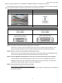
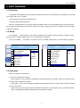
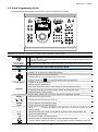
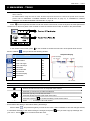
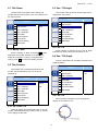
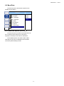
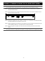
195Z
User Manual
Please read instructions thoroughly before operation and retain it for future reference.
The image shown above may differ from the actual product appearance.
321Z_322Z_Manual_V1.0
IMPORTANT SAFEGUARD
CAUTION
RISK OF ELECTRIC SHOCK
CAUTION:
To reduce the risk of electric shock, do not expose this apparatus to rain or moisture. Only operate this apparatus
from the type of power source indicated on the label. The company shall not be liable for any damages arising out
of any improper use, even if we have been advised of the possibility of such damages.
Graphic Symbol Explanation
The lightning flash with arrowhead symbol, within an equilateral triangle, is intended to alert the user
to the presence of uninsulated “dangerous voltage” within the product’s enclosure that may be of
sufficient magnitude to constitute a risk of electric shock to persons.
This exclamation point within an equilateral triangle is intended to alert the user to the presence of
important operating and maintenance (servicing) instructions in the literature accompanying the
appliance.
All lead-free products offered by the company comply with the requirements of the European law on
the Restriction of Hazardous Substances (RoHS) directive, which means our manufacture processes
and products are strictly “lead-free” and without the hazardous substances cited in the directive.
The crossed-out wheeled bin mark symbolizes that within the European Union the product must be
collected separately at the product end-of-life. This applies to your product and any peripherals
marked with this symbol. Do not dispose of these products as unsorted municipal waste. Contact your
local dealer for procedures for recycling this equipment.
This apparatus is manufactured to comply with the radio interference requirements.
About this document
We reserve the right to revise or remove any content in this manual at any time. We do not warrant or assume any
legal liability or responsibility for the accuracy, completeness, or usefulness of this manual. For the actual display
and operation, please refer to your camera in hand. The content of this manual is subject to change without notice.
Precautions
‧
Avoid the long-term activation for “Auto Tracking”, “Auto Pan”, and “Sequence” as it might accelerate the
aging of the drive mechanism and optical lens. Three-month warranty applies only to certain parts related to
these three functions.
‧
Do not shoot images that are extremely bright for a long time (For example, light sources, the sun, etc.).
‧
Don’t use or store the camera in the following conditions: (1) Extremely hot or cold places (operating
temperature -10∘C ~ 40∘C (= 14∘F ~ 104∘F) ) (2) Close to generators of powerful electromagnetic
radiation such as radio or TV transmitters. (3) Where it is subject to fluorescent light reflections. (4) Where it is
subject to unstable lighting (flickering, etc.) conditions. (5) Where it is subject to strong vibration. (6) Where it
is near water or in contact with water.
‧
Installation should be made by qualified service personnel.
TABLE OF CONTENTS
1. INTRODUCTION ...................................................................................................................... 1
1.1 Overview..........................................................................................................................................................1
1.2 Features...........................................................................................................................................................1
1.3 Package Contents ...........................................................................................................................................1
1.4 Specifications...................................................................................................................................................2
2. INSTALLATION AND SETUP .................................................................................................. 3
2.1 Installation........................................................................................................................................................3
2.2 Connection.......................................................................................................................................................4
2.2.1 Connecting to Keyboard Controller (Optional) .......................................................................................4
2.2.2 Connecting to DVR ................................................................................................................................5
3. AUTO TRACKING .................................................................................................................... 8
3.1 Overview..........................................................................................................................................................8
3.2 Setup ...............................................................................................................................................................8
3.3 Activation .........................................................................................................................................................8
4. QUICK MENU GUIDE .............................................................................................................. 9
4.1 Menu Configuration .........................................................................................................................................9
4.2 Quick Programming Guide.............................................................................................................................10
5. MAIN MENU – CAMERA ....................................................................................................... 11
5.1 White Balance................................................................................................................................................12
5.1.1 Auto .....................................................................................................................................................12
5.1.2 Indoor 1 / Indoor 2 / Sun / Cloudy ........................................................................................................12
5.2 Shutter Speed ................................................................................................................................................12
5.2.1 Shutter Speed Options.........................................................................................................................12
5.3 Gain (Gain Control)........................................................................................................................................12
5.3.1 On (Low, Medium, High) / Off ..............................................................................................................12
5.4 IRIS................................................................................................................................................................13
5.4.1 Auto IRIS Level (50 ~ 250)...................................................................................................................13
5.5 BLC (Backlight Compensation)......................................................................................................................13
5.5.1 On / Off ................................................................................................................................................13
5.6 Sharpness......................................................................................................................................................13
5.6.1 Auto .....................................................................................................................................................13
5.6.2 Sharpness Level ..................................................................................................................................13
6. MAIN MENU – TOOLS........................................................................................................... 14
6.1 Title Name......................................................................................................................................................15
6.1.1 Modify / New........................................................................................................................................15
6.2 Title Position ..................................................................................................................................................15
6.2.1 Up / Down / Off ....................................................................................................................................15
6.3 Pan / Tilt Angle...............................................................................................................................................15
6.3.1 On / Off ................................................................................................................................................15
6.4 Pan / Tilt Graph..............................................................................................................................................15
6.4.1 On / Off ................................................................................................................................................15
6.5 Zoom Bar .......................................................................................................................................................16
6.5.1 On / Off ................................................................................................................................................16
6.6 Focus Window ...............................................................................................................................................16
6.6.1 On / Off ................................................................................................................................................16
6.7 ID Code No. ...................................................................................................................................................16
6.7.1 Camera ID Code Number Setup..........................................................................................................16
6.8 ID Code Display.............................................................................................................................................16
6.8.1 On / Off ................................................................................................................................................16
6.9 Baud Rate......................................................................................................................................................17
6.9.1 Baud Rate Options (unit: bits/s) ...........................................................................................................17
7. MAIN MENU – STATUS ......................................................................................................... 18
8. MAIN MENU – MODE ............................................................................................................ 19
8.1 Reset Default .................................................................................................................................................20
8.2 Pan / Tilt Speed..............................................................................................................................................20
8.3 Preset Setup ..................................................................................................................................................20
8.3.1 Set the Preset Points ...........................................................................................................................20
8.3.2 Factory Default Preset Points ..............................................................................................................20
8.3.3 Add New Preset Points ........................................................................................................................21
8.3.4 Set Duration Time of the Preset Points................................................................................................21
8.3.5 Deleting the Preset Points ...................................................................................................................21
8.3.6 Preview the Preset Points....................................................................................................................21
8.3.7 Exit the Preset Point Setting Menu ......................................................................................................21
8.4 Tracking Setup...............................................................................................................................................22
8.4.1 Set the Pre-defined Surveillance Area (=LIMIT=) ................................................................................22
8.4.2 Set the Pre-defined Tracking Timeout (=TIME=) .................................................................................22
8.4.3 Select the Auto Tracking Mode (Mode)................................................................................................22
8.5 Home Position ...............................................................................................................................................23
8.5.1 Set the Home Position .........................................................................................................................23
8.6 Auto Focus.....................................................................................................................................................23
8.6.1 Select the Auto Focus Mode................................................................................................................23
8.7 Calibration......................................................................................................................................................23
8.7.1 Select the Calibrating Result ...............................................................................................................24
8.8 Auto Scan ......................................................................................................................................................24
8.8.1 Set the Pan Angel Limit .......................................................................................................................24
8.9 Auto Mode......................................................................................................................................................24
8.9.1 Set the Auto Mode ...............................................................................................................................24
9. MAIN MENU – EXIT ............................................................................................................... 25
9.1 Exit & Save the Changes ...............................................................................................................................25
9.2 Exit Without Saving the Changes ..................................................................................................................25
APPENDIX 1 DEFAULT VALUE ................................................................................................ 26
APPENDIX 2 CAMERA CONTROL VIA OUR DVR................................................................... 27
APPENDIX 3 CAMERA CONTROL VIA OTHER KEYBOARD CONTROLLER ....................... 28
APPENDIX 4 FIRMWARE UPGRADE FOR 22X SPEED DOME CAMERA ............................. 29
INTRODUCTION
1. INTRODUCTION
1.1 Overview
Equipped with a 360° pan and 90° tilt base and 22X optical zoom lens, this outdoor type speed dome camera is
capable of following the moving object precisely with Intelligent Auto Tracking, and long-time operation with High
Spindle Reliability. Moreover, its Friendly Graphical OSD Interface and Convenient Keyboard Controller Control
support make the operation and surveillance simpler. With all these strong features, various demanding applications
for safety surveillance can be easily achieved.
1.2 Features
Advanced Auto Tracking Accuracy
‧ With precise pan / tilt movement and zoom coefficient calculation, the speed dome camera can make precise pan,
tilt and zoom movement to keep tracking intruders.
High-Speed Pan/Tilt Mechanism and Auto-Focus Zoom Lens
‧ Provides 360∘panning, 90∘tilting and 22X optical zooming functionality.
Proven Spindle Reliability
‧ The patented spindle of the speed dome camera passes rigidly component analysis after testing more than
2,000,000 revolutions.
Pelco-D & Pelco-P Support
‧ For fully compatibility
Flexible Color / Shutter Parameters Adjustment
‧ Adapts various light conditions easily
Graphical On-Screen Display
Hot Point
Easy Operation via Keyboard Controller
‧ The optional keyboard controller provides convenient 3D joystick and touch screen design for easy operation.
IP 67, suitable for outdoor use
Up to 256 preset points and eight preset groups, and Auto Scan
1.3 Package Contents
◎ In the camera package:
□ Speed dome camera
□ User Manual
□ CD-ROM disc (including user manuals &
CMS software “Video Viewer”)
◎ In the bracket package (Optional) :
□ Wall mounting screws x 4
□ Wall plugs x 4
□ Cap x 1
□ Bracket screw x 1
□ M6 Nylok screws (short) x 2
□ M6 Nylok screws (long) x 3
□ M4 screw x 1
□ Mounting base screw x 2
□ Spirit level x 1
□ Hex screw nuts x 3
-1-
INTRODUCTION
1.4 Specifications
Outdoor 22X Zoom Speed Dome Camera
▓ GENERAL
Signal System
NTSC or PAL
Pick-up Element
1/4" Sony Color Super HAD CCD image sensor
Number of Pixels
768(H)*494(V)<NTSC> / 752(H)*582(V)<PAL>
Resolution
High Resolution
Min. Illumination
0.3 Lux / F1.6
S/N Ratio
More than 48dB (AGC off)
Video Output
1.0 Vp-p. 75Ω
BLC
On / Off
Gain Control
Low, Medium & High / Off
Sharpness
Auto / Low / Medium / High
White Balance
Auto / Indoor 1 / Indoor 2 / Sun / Cloudy
* Indoor1 = 9000K; Indoor2 = 3000K; Sun = 5500K; Cloudy = 7000K
Camera Title
Preset Points and Sequence
Auto Tracking
10 characters or symbols
Total 8 groups, 256 programmable preset points
* The sequence of all the preset points will follow the order of the minimal panning route.
Yes
▓ LENS
Focal Length
f3.9 mm ~ f85.9 mm
F-number
F1.6 (Wide) ~ 3.7 (Tele)
Viewing Angle
4∘~ 60∘
Auto Electronic Shutter
1 / 60 (1/50) to 1 / 100,000 sec.
Auto Focus
Always / PTZ / Z Only / P Only
▓ MECHANISM
Pan Range
Pan Speed
360∘
360∘/ 1 sec
* The pan speed can be adjusted according to the different pan speed mode.
Tilt Range
90∘
Tilt Speed
0∘~ 90∘under 1 sec
Zoom Ratio
22X optical zoom
Zoom Speed
Approx. 7s (Tele ~ Wide)
▓ OTHERS
IP Rating
IP67
Ambient Operating Temperature
-10°C ~ 40°C (14°F ~ 104°F)
Power Source (±10%)
DC12V
Current Consumption
1.5A (max)
Dimension (mm)**
145(Ø) x 184(H)
Gross Weight (g)
Approx. 1.2 kg
Optional Bracket
Wall-mounted
Optional Device
Keyboard controller
* The specifications are subject to change without notice.
** Dimensional Tolerance: ±5mm
-2-
INSTALLATION AND SETUP
2. INSTALLATION AND SETUP
For the installation and connection of this speed dome camera, please check with qualified service personnel or
installer.
2.1 Installation
Before installation, you need the following items before installation:
‧
Bracket & mounting base (supplied with the bracket sales package)
‧
The accessory packages supplied with the bracket sales package, including:
‧
(1) Wall mounting screws x 4
(2) Wall plugs x 4
(3) Cap x 1
(4) Bracket screw x 1
(5) M6 Nylok screws (short) x 2
(6) M6 Nylok screws (long) x 3
(7) M4 screw x 1
(8) Mounting base screw x 2
(9) Spirit level x 1
(10) Hex screw nuts x 3
Power Drill
-3-
INSTALLATION AND SETUP
2.2 Connection
2.2.1 Connecting to Keyboard Controller (Optional)
The optional peripheral (keyboard controller) allows you to accurately control the pan / tilt / zoom movement for a
speed dome camera with the convenient 3D joystick and functional keypad design.
Note: It’s highly recommended to purchase this device to work with your speed dome camera for accurate control.
The following connection illustration is an example. For detailed connection and operation guide, please refer to
your keyboard controller manual.
-4-
INSTALLATION AND SETUP
Rear panel of the keyboard controller:
AUDIO
EXTERNAL I/O
DVR P.T.Z
LAN
DC 12V
RJ11 Line
RS485-A and RS485-B wires of the speed dome
camera
RS485-A: Red wire
RS485-A: Brown wire
RS485-B: Green wire
RS485-B: Orange wire
The RJ11 line is not supplied in the sales package.
Example of RS485-A and RS485-B wires of the speed dome
camera.
STEP 1: Get a RJ11 line with the proper length to your connection.
Different RJ11 connector may have different wire layout, so the connection might be different. If you
cannot control the speed dome camera after connection, please reverse the RJ11 line connection with
the speed dome camera.
STEP 2: Remove one end of the insulating coating of the RJ11 line.
Remove one end of the insulating coating of the RJ11 line to find the RS485-A and the RS485-B wires,
and remove the insulating coating to reveal the naked wires for further connection.
STEP 3: Twist the RS485-A and RS485-B wires together.
Twist the RS485-A (red) and RS485-B (green) wires of the RJ11 line to the RS485-A (brown) and
RS485-B (orange) wires of the speed dome camera (as shown in the picture above). To protect the
naked wires, use the insulation tape to cover on the twisted wires.
STEP 4: Connect the RJ11 connector to the “P.T.Z” port on the rear panel of the keyboard controller.
STEP 5: On the touch panel of the keyboard controller, click “Conf” to enter the configuration page, and
click
(P.T.Z) to make related settings as follows.
●
RATE
: Check and select the baud rate the same as the connected speed dome camera
is used.
MODE
: Choose the proper camera protocol depending on the camera type.
STEP 6: Then, click “ESC” as many as needed to return to the main menu, and assign the ID of the
camera.
STEP 7: Connect the camera video cable to the DVR for video output and recording, and connect the
camera to power.
2.2.2 Connecting to DVR
You can also connect the camera directly to DVR for pan / tilt / zoom control, but the available camera control is
-5-
INSTALLATION AND SETUP
limited. For details, please refer to “APPENDIX 2 CAMERA CONTROL VIA OUR DVR” at page 27.
The following description is taking our brand’s DVR as an example. For detailed PIN / port connection and DVR
setting to control the speed dome camera, please refer to your own DVR user manual.
RJ11 Line
RS-485 Port
RS485-A: Red wire
RS485-A: PIN 2
RS485-B: Green wire
RS485-B: PIN 3
The RJ11 line is not supplied in the sales package.
Example of RS485 port on the DVR rear panel.
PIN Connection
For 15 PIN D-Sub Connector:
For 25 PIN D-Sub Connector:
RS485-A: PIN 11
RS485-B: PIN 10
RS485-A: PIN 12
RS485-B: PIN 24
Solder Side of
15-pin D-Sub connector
Solder Side of
25-pin D-Sub connector
RS485 -A: PIN12 / RS485-B: PIN2 4
RS485 -A: PIN11 / RS485-B: PIN1 0
8
7
15 14
16
6
5
13
4
12
3
11
2
13 12 11 10
1
9
8
7
6
5
4
3
2 1
25 24 23 22 21 20 19 18 17 16 15 14
10
9
17
D-Sub connector is supplied with the DVR package.
STEP 1: Get a RJ11 line with the proper length to your connection.
Different RJ11 connector may have different wire layout, so the connection might be different. If you
cannot control the DVR after connection, please reverse the RJ11 line connection with the DVR.
STEP 2: Remove one end of the insulating coating of the RJ11 line.
Remove one end of the insulating coating of the RJ11 line to find the RS485-A and the RS485-B wires,
and remove the insulating coating to reveal the naked wires for further connection.
STEP 3: Twist the RS485-A and RS485-B wires of the RJ11 line and the speed dome camera together.
Twist the RS485-A (red) and RS485-B (green) wires of the RJ11 line to the RS485-A (brown) and
RS485-B (orange) wires of the speed dome camera (as shown in the picture above). To protect the
naked wires, use the insulation tape to cover on the twisted wires.
STEP 4: Connect the other end of the RJ11 line to DVR.
When there’s an RS485 port on the DVR real panel
Connect the other end of the RJ11 line without removing the insulating coating directly to the RS485 port
on the DVR real panel.
-6-
INSTALLATION AND SETUP
When there’s an external I/O port on the DVR real panel
Solder the RS485-A (red) and RS485-B (green) wires of the RJ11 line to the corresponding pins on the
solder side of the 15 PIN or 25 PIN D-Sub connector (as shown in the picture above). To protect the
naked wires, use the insulation tape to cover on the twisted wires.
STEP 5: Set the speed dome camera at the DVR side.
Go to the “REMOTE” menu to set the speed dome camera.
a) Select the device to “PTZ”.
b) Set the ID to the value the same as the one set in the speed dome camera. The default ID shown on
the main menu is 000.
c) Select the protocol to “NORMAL”.
d) Set the baud rate to the value the same as the one set in the speed dome camera. The default baud
rate shown on the main menu is 2400.
REMOTE
TITLE
DEVICE
ID
PROTOCOL
RATE
CH1
CH2
CH3
CH4
PTZ
CAMERA
CAMERA
CAMERA
000
000
000
000
NORMAL
NORMAL
NORMAL
NORMAL
2400
2400
2400
2400
PLEASE CONSULT YOUR INSTALLER FOR ADVANCE SETTING
uv SELECT s BACK t NEXT ENTER
-7-
AUTO TRACKING
3. AUTO TRACKING
3.1 Overview
The camera will automatically aim and follow the largest movement in the monitoring view, making the camera pan
(max. 360o) & tilt (max. 90o) within:
(1) the camera's pre-defined surveillance area;
(2) the pre-defined tracking timeout.
When the locked target is out of the pre-defined surveillance area or the aimed object stops moving longer than
the pre-defined tracking timeout, the camera returns to the point it originally monitors. It's the best function to provide
evidentiary recording.
3.2 Setup
Go to “MODE” l “Tracking Setup”, and set the surveillance area (=LIMIT=), tracking timeout (=TIME=), and the
tracking mode. For details, please refer to “8.4 Tracking Setup” at page 22.
Then, go to “MODE” l “Auto Mode”, and select “Track”. For details, please refer to “8.9 Auto Mode” at page 24.
.
MODE
1
Reset Default
2
Pan / Tilt Speed
3
Preset Setup
4
Tracking Setup
5
Home Position
6
Auto Focus
7
MODE
=LIMIT=
1
Reset Default
Track
60°
2
Pan / Tilt Speed
Pan
=TIME=
3
Preset Setup
Seq.
4
Tracking Setup
=Mode=
5
Home Position
Normal
6
Auto Focus
Calibration
7
Calibration
8
Auto Scan
8
Auto Scan
9
Auto Mode
9
Auto Mode
5s
3.3 Activation
When the camera is controlled via:
(1) Our brand’s keyboard controller -Press “TRACK” on the controller to activate the auto tracking function, and press “STOP” to stop the function.
(2) Other brand’s keyboard controller -Press “goto” + “90” on the controller to activate the auto tracking function, and press again to stop the function.
(3) Our brand’s DVR -Press “PLAY” on the DVR front panel to activate the auto mode, and press again to stop. For details, please
refer to “APPENDIX 2 CAMERA CONTROL VIA OUR DVR” at page 27.
-8-
MAIN MENU – CAMERA
4. QUICK MENU GUIDE
4.1 Menu Configuration
Setup menu is shown as below. You can customize the speed dome camera to your own requirements by setting
up the respective items in these menus. For details, please refer to the corresponding pages.
White Balance
Auto, Indoor 1, Indoor 2, Sun, Cloudy
NTSC
1/60, 1/100, 1/250, 1/500, 1/1000, 1/2000,
1/4000, 1/10000
PAL
1/50, 1/120, 1/250, 1/500, 1/1000, 1/2000,
1/4000, 1/10000
Shutter Speed
CAMERA
Gain
Low, Medium, High, Off
IRIS
TOOL
STATUS
MODE
BLC
On, Off
Sharpness
Auto, Low, Medium, High
Title Name
Modify, New
Title Position
Up, Down, Off
Pan / Tilt Angle
On, Off
Pan / Tilt Graph
On, Off
Zoom Bar
On, Off
Focus Window
On, Off
ID Code No.
1
ID Code Display
On, Off
Baud Rate
19200, 9600, 4800, 2400
Auto Focus
Yes
Motion Detect
Yes
Auto Tracking
Yes
Pan Motor
75
Tilt Motor
183
Zoom Motor
21
Reset Setting
Set
Pan / Tilt Speed
Slow, Fast, Super
Preset Setup
Group 1 ~ Group 8
Tracking Setup
LIMIT, TIME, Mode
Home Position
Set
Auto Focus
Always, PTZ, Z Only
Calibration
Start
Auto Scan
Set
Auto Mode
Track, Pan, Seq.
SAVING
EXIT
WITHOUT SAVING
* The menu items are subject to change without notice.
-9-
MAIN MENU – CAMERA
4.2 Quick Programming Guide
The optional keyboard controller can be used to control this speed dome camera.
Note: Please enter the camera control mode of the keyboard controller first.
Enter the Camera
Control Mode
KEYS
(1)
” to enter the camera control mode.
Press “
Or use the stylus to click the speed dome camera icon on the touch panel to enter the
camera control mode.
(2)
In the camera control mode, the LED indicator of the speed dome camera will be on.
OPERATIONS UNDER THE CAMERA CONTROL MODE
Press to access the main menu of the speed dome camera.
Press the up or down key to make the selection.
Press the right key to enter the sub-menu.
Press the left key to go the upper layer of the menu.
Press the enter key “
F1, F2, F3, F4
” to confirm the setting / enter the sub-menu
HOME: Go to the home position
GOTO: Go to the preset point
HOTKEY
SEQ: Start sequence function. Press “STOP” to exit the sequence mode.
AUTO PAN: Start the pan function. Press “STOP” to exit the pan mode.
NONE: Saved for future functions
* For detailed hotkey function setup, please refer to the user manual of the keyboard controller.
- FOCUS +
Adjust the focus of the camera.
/
Press these keys to zoom out / zoom in.
TRACK
STOP
Press to start the auto-tracking function.
Press to stop the auto-tracking function.
- / +
0~9
ESC
Use the - / + to modify the setting of the IRIS level / the ID code number / the auto
tracking setting.
Use this number pad to enter the camera ID, channel number and password, etc.
Ignore the setting and exit.
Confirm the number / password entering.
Use the joystick to control the camera to move up / down / left / right.
Turn the joystick clockwise to zoom in. Turn the joystick counter-clockwise to zoom out.
-10-
MAIN MENU – CAMERA
5. MAIN MENU – CAMERA
Note: The following description assumes that users are using our brand’s keyboard controller to control the speed
dome camera.
For details about using the DVR or other brand’s keyboard controller to control the speed dome camera,
please refer to “APPENDIX 2 CAMERA CONTROL VIA OUR DVR” at page 27, or “APPENDIX 3 CAMERA
CONTROL VIA OTHER KEYBOARD CONTROLLER” at page 28.
Press
on the keyboard controller to enter the camera control mode, or use the stylus to click the speed dome
camera icon on the touch panel of the controller to enter the camera control mode, as shown in the picture below.
Note: Make sure the camera ID shown on the main menu of the keyboard controller is the same as the ID set in
the camera, or you will be unable to control the camera you want.
In the camera control mode, press
Move to CAMERA “
on the controller to access the main menu of the speed dome camera.
”, and you will see the following window:
CAMERA
1
White Balance
Auto
2
Shutter Speed
1/60
3
Gain
Medium
4
IRIS
5
BLC
Off
6
Sharpness
Auto
Note: The current settings will be shown on the right hand side of this menu page.
Press to access the main menu of the speed dome camera.
Press the up or down key to make the selection.
Press the right key to enter the sub-menu.
Press the left key to go the upper layer of the menu.
- / +
Press - / + to modify the setting of the IRIS level in the menu.
‧ Exit and Save the Settings / Exit without Saving the Settings:
Move to EXIT “
”, and press the right key to enter the sub-menu. Select “SAVING” to save the changes and exit,
or “WITHOUT SAVING” to exit without saving the changes, and press
your sure ?”. Press
again to confirm and exit the menu.
-11-
. Then you’ll see a pop-up message “Are
MAIN MENU – CAMERA
5.1 White Balance
5.2.1 Shutter Speed Options
The white balance function processes the current
image to retain color balance over a color temperature
range. According to different color temperatures and
installation situations, set the white balance function to
the suitable mode.
NTSC: 1/60, 1/100, 1/250, 1/500, 1/1000, 1/2000, 1/4000, 1/10000
PAL:
The camera has eight numerical shutter speed
options. The higher the number, the faster the
electronic shutter. Increasing the shutter speed will
lower the amount of light passing through the lens.
CAMERA
1
White Balance
Auto
2
Shutter Speed
Indoor 1
3
Gain
Indoor 2
4
IRIS
Sun
5
BLC
Cloudy
6
Sharpness
1/50, 1/120, 1/250, 1/500, 1/1000, 1/2000, 1/4000, 1/10000
The slowest shutter speed setting is 1/60 second
(NTSC) or 1/50 second (PAL).
The fastest shutter speed setting is 1/10000
second.
Note: When you use a NTSC camera in the PAL
system environment, set the shutter speed as
1/100, and the image output will be equal to
the output under the flickerless mode.
5.1.1 Auto
Note: When you use a PAL camera in the NTSC
system environment, set the shutter speed as
Adjust the color automatically depending on
different color temperatures.
1/120, and the image output will be equal to
the output under the flickerless mode.
5.1.2 Indoor 1 / Indoor 2 / Sun / Cloudy
You can select different white balance modes
provided here to adjust the image output. As you
change the setting, you will see the color change on
your monitor.
5.3 Gain (Gain Control)
Gain control is a function to adjust the amplitude of
the signal input according to different light conditions.
Mode
Color Temperature
Indoor 1
9000K
Indoor 2
3000K
1
White Balance
Low
Sun
5500K
2
Shutter Speed
Medium
Cloudy
7000K
3
Gain
High
4
IRIS
Off
5
BLC
6
Sharpness
CAMERA
5.2 Shutter Speed
Shutter speed is the duration of the electronic
shutter. There are eight pre-defined shutter speed
options for your choice.
5.3.1 On (Low, Medium, High) / Off
CAMERA
1
White Balance
1/ 60
2
Shutter Speed
1/ 100
3
Gain
1/ 250
4
IRIS
1/ 500
5
BLC
1/ 1000
6
Sharpness
1/ 2000
When the light condition is dark, you can select
three kinds of sensitivities, Low / Medium (default) /
High, to amplify the camera signal to get brighter
display.
When the light condition is often normal and it’s not
necessary to enable the gain control function, you can
select “Off” to disable it.
1/ 4000
1/ 10000
Note: The higher the sensitivity is, the more the
signal noise will be.
-12-
MAIN MENU – CAMERA
5.4 IRIS
5.6 Sharpness
Auto iris is the lens function that automatically
opens and closes the iris in response to the changing
light conditions.
Auto sharpness enhances the clarity of image
detail by adjusting the aperture and sharpening the
edges in the pictures.
CAMERA
CAMERA
1
White Balance
Auto
2
Shutter Speed
Low
3
Gain
Medium
High
1
White Balance
2
Shutter Speed
3
Gain
4
IRIS
4
IRIS
5
BLC
5
BLC
6
Sharpness
6
Sharpness
162
5.6.1 Auto
5.4.1 Auto IRIS Level (50 ~ 250)
The camera automatically maintains a normal
sharpness mode.
Auto iris level is the numeric value the auto iris
uses to maintain the brightness level of the camera.
Use “+” to increase the value to brighten the scene.
Use “-” to decrease the level to darken the scene.
5.6.2 Sharpness Level
The image sharpness can be set to different
sharpness levels (Low / Medium / High) as needed.
5.5 BLC (Backlight Compensation)
The BLC, or backlight compensation, is the
function to adjust the image to compensate for an area
that is overpowered by brightness because of
excessive light. The image will be properly exposed for
clearness.
CAMERA
1
White Balance
On
2
Shutter Speed
Off
3
Gain
4
IRIS
5
BLC
6
Sharpness
5.5.1 On / Off
The backlight compensation can be set on or off.
-13-
MAIN MENU – TOOLS
6. MAIN MENU – TOOLS
Note: The following description assumes that users are using our brand’s keyboard controller to control the speed
dome camera.
For details about using the DVR or other brand’s keyboard controller to control the speed dome camera,
please refer to “APPENDIX 2 CAMERA CONTROL VIA OUR DVR” at page 27, or “APPENDIX 3 CAMERA
CONTROL VIA OTHER KEYBOARD CONTROLLER” at page 28.
Press
on the keyboard controller to enter the camera control mode, or use the stylus to click the speed dome
camera icon on the touch panel of the controller to enter the camera control mode, as shown in the picture below.
In the camera control mode, press
Move to TOOLS “
on the controller to access the main menu of the speed dome camera.
”, and you will see the following window:
Graphical Display
TOOLS
1
Title Name
Set
2
Title Position
Up
3
Pan / Tilt Angle
On
4
Pan / Tilt Graph
On
5
Zoom Bar
On
6
Focus Window
On
7
ID Code No.
0
8
ID Code Display
On
9
Baud Rate
2400
Note: The current settings will be shown on the right hand side of this menu page.
Press to access the main menu of the speed dome camera.
Press the up or down key to make the selection.
Press the right key to enter the sub-menu.
Press the left key to go the upper layer of the menu.
Press the enter key “
- / +
” to confirm the setting / enter the sub-menu
Press - / + to modify the ID code number.
‧ Exit and Save the Settings / Exit without Saving the Settings:
Move to EXIT “
”, and press the right key to enter the sub-menu. Select “SAVING” to save the changes and exit,
or “WITHOUT SAVING” to exit without saving the changes, and press
your sure ?”. Press
again to confirm and exit the menu.
-14-
. Then you’ll see a pop-up message “Are
MAIN MENU – TOOLS
6.1 Title Name
6.3 Pan / Tilt Angle
The title name is the label used to identify the
camera viewed on the monitor. Up to 10 characters can
be used for a title.
The numeric value of the pan and tilt angle can be
displayed on the monitor.
TOOLS
TOOLS
1
Title Setting
On
Off
1
Title Name
Modify
2
Title Position
2
Title Position
New
3
Pan / Tilt Angle
3
Pan / Tilt Angle
4
Pan / Tilt Graph
4
Pan / Tilt Graph
5
Zoom Bar
5
Zoom Bar
6
Focus Window
6
Focus Window
7
ID Code No.
7
ID Code No.
8
ID Code Display
8
ID Code Display
9
Baud Rate
9
Baud Rate
6.3.1 On / Off
6.1.1 Modify / New
Select whether to display the pan and tilt angle
information (numeric value) on the monitor or not.
Move to “Modify” or “New”, and press
to start
editing the camera title. Use the up or down key to
select the characters, numbers, or symbols. After
setting, press
6.4 Pan / Tilt Graph
to confirm the setting and exit.
The pan / tilt position can be easily checked on this
graphical display.
6.2 Title Position
TOOLS
The position of the camera title viewed on the
monitor can be selected by your own or can be
switched off.
TOOLS
1
Title Setting
Up
2
Title Position
Down
3
Pan / Tilt Angle
Off
4
Pan / Tilt Graph
5
Zoom Bar
6
Focus Window
7
ID Code No.
8
ID Code Display
9
Baud Rate
1
Title Setting
On
2
Title Position
Off
3
Pan / Tilt Angle
4
Pan / Tilt Graph
5
Zoom Bar
6
Focus Window
7
ID Code No.
8
ID Code Display
9
Baud Rate
6.4.1 On / Off
Select whether to display the pan/ tilt graphical
display on the monitor or not.
6.2.1 Up / Down / Off
Select to display the camera title name on the top
of (Up) / at the bottom (Down) of the monitor, or choose
not to display the title (Off).
-15-
MAIN MENU – TOOLS
6.5 Zoom Bar
6.7 ID Code No.
The zoom ratio can be easily checked on this
zoom bar graph.
The camera ID code number is a series of digits
that indicate the location of the camera.
TOOLS
TOOLS
1
Title Setting
On
1
Title Setting
2
Title Position
Off
2
Title Position
3
Pan / Tilt Angle
3
Pan / Tilt Angle
4
Pan / Tilt Graph
4
Pan / Tilt Graph
5
Zoom Bar
5
Zoom Bar
6
Focus Window
6
Focus Window
7
ID Code No.
7
ID Code No.
8
ID Code Display
8
ID Code Display
9
Baud Rate
9
Baud Rate
1
6.5.1 On / Off
6.7.1 Camera ID Code Number Setup
Select whether to display the zoom bar graph on
the monitor or not.
Use - or +, S or T, or the number pad to set
the camera ID code number in the menu.
6.8 ID Code Display
6.6 Focus Window
The camera ID code number can be displayed on
the monitor.
The focus window can be showed on the monitor.
TOOLS
TOOLS
1
Title Setting
On
2
Title Position
Off
3
Pan / Tilt Angle
4
Pan / Tilt Graph
5
Zoom Bar
6
Focus Window
7
ID Code No.
8
ID Code Display
9
Baud Rate
6.6.1 On / Off
1
Title Setting
On
2
Title Position
Off
3
Pan / Tilt Angle
4
Pan / Tilt Graph
5
Zoom Bar
6
Focus Window
7
ID Code No.
8
ID Code Display
9
Baud Rate
6.8.1 On / Off
Select whether to show the focus window on the
monitor or not.
Select to whether to display the ID number
information on the monitor or not.
-16-
MAIN MENU – TOOLS
6.9 Baud Rate
The baud rate is the transmission speed for the
RS485 communication.
TOOLS
1
Title Setting
19200
2
Title Position
9600
3
Pan / Tilt Angle
4800
4
Pan / Tilt Graph
2400
5
Zoom Bar
6
Focus Window
7
ID Code No.
8
ID Code Display
9
Baud Rate
6.9.1 Baud Rate Options (unit: bits/s)
The baud rate of the camera must be the same as
the connected control device (such as DVR or
keyboard controller) for the control to take effect.
The available options are 19200 / 9600 / 4800 /
2400 bits per second for the RS485 communication.
The factory default setting is 2400.
-17-
MAIN MENU – FUNCTION
7. MAIN MENU – STATUS
Note: The following description assumes that users are using our brand’s keyboard controller to control the speed
dome camera.
For details about using the DVR or other brand’s keyboard controller to control the speed dome camera,
please refer to “APPENDIX 2 CAMERA CONTROL VIA OUR DVR” at page 27, or “APPENDIX 3 CAMERA
CONTROL VIA OTHER KEYBOARD CONTROLLER” at page 28.
Press
on the keyboard controller to enter the camera control mode, or use the stylus to click the speed dome
camera icon on the touch panel of the controller to enter the camera control mode, as shown in the picture below.
In the camera control mode, press
Move to STATUS “
on the controller to access the main menu of the speed dome camera.
”, and and you will see the following window:
STATUS
1
Auto Focus
Yes
2
Motion Detect
Yes
3
Auto Tracking
Yes
4
Pan Motor
75
5
Tilt Motor
183
6
Zoom Motor
21
You cannot make any selection to this menu. This is just for your quick checking only.
-18-
MAIN MENU – MODE
8. MAIN MENU – MODE
Note: The following description assumes that users are using our brand’s keyboard controller to control the speed
dome camera.
For details about using the DVR or other brand’s keyboard controller to control the speed dome camera,
please refer to “APPENDIX 2 CAMERA CONTROL VIA OUR DVR” at page 27, or “APPENDIX 3 CAMERA
CONTROL VIA OTHER KEYBOARD CONTROLLER” at page 28.
Press
on the keyboard controller to enter the camera control mode, or use the stylus to click the speed dome
camera icon on the touch panel of the controller to enter the camera control mode, as shown in the picture below.
In the camera control mode, press
Move to MODE “
on the controller to access the main menu of the speed dome camera.
”, and you will see the following window:
MODE
1
Reset Default
Set
2
Pan / Tilt Speed
Fast
3
Preset Setup
Group_1
4
Tracking Setup
60°
5
Home Position
Set
6
Auto Focus
PTZ
7
Calibration
Start
8
Auto Scan
Set
9
Auto Mode
Track
5s
Note: The current settings will be shown on the right hand side of this menu page.
Press to access the main menu of the speed dome camera.
Press the up or down key to make the selection.
Press the right key to enter the sub-menu.
Press the left key to go the upper layer of the menu.
Press the enter key “
- / +
” to confirm the setting / enter the sub-menu.
Press - / + to modify the auto tracking angle.
‧ Exit and Save the Settings / Exit without Saving the Settings:
Move to EXIT “
”, and press the right key to enter the sub-menu. Select “SAVING” to save the changes and exit,
or “WITHOUT SAVING” to exit without saving the changes, and press
your sure ?”. Press
again to confirm and exit the menu.
-19-
. Then you’ll see a pop-up message “Are
MAIN MENU – MODE
8.1 Reset Default
8.3 Preset Setup
To restore all camera settings to the factory default
The preset point setting is used to specify the
camera position (pan and tilt) and the lens zoom setting.
You can set up to 256 preset points (8 groups, each
group has 32 preset points).
settings, move to “Set”, and press
to confirm.
When you see the message “Initial…OK” on the
monitor, all the camera settings are reset to default
settings. To exit the message window, press the left
key.
MODE
MODE
1
Reset Default
2
Pan / Tilt Speed
3
Preset Setup
4
Tracking Setup
5
Home Position
6
Auto Focus
7
Calibration
8
Auto Scan
9
Auto Mode
Set
1
Reset Default
Group_1
2
Pan / Tilt Speed
Group_2
3
Preset Setup
Group_3
4
Tracking Setup
Group_4
5
Home Position
Group_5
6
Auto Focus
Group_6
7
Calibration
Group_7
8
Auto Scan
Group_8
9
Auto Mode
8.3.1 Set the Preset Points
Move to “Group_1”, and press
to enter the
setting mode. You will see a similar preset point window
as shown in the picture below.
8.2 Pan / Tilt Speed
The pan / tilt speed can be set to Slow / Fast /
Super (super fast).
MODE
1
Reset Default
Slow
2
Pan / Tilt Speed
Fast
3
Preset Setup
Super
4
Tracking Setup
5
Home Position
6
Auto Focus
7
Calibration
8
Auto Scan
9
Auto Mode
8.3.2 Factory Default Preset Points
For convenience, there are two factory-default
preset points within each preset group. The first
position is “Pan: 120∘; Tilt: 15∘”. and the second
position is “Pan: 240∘; Tilt: 15∘”.
The preview graphs of the factory-default preset
points are shown as below.
Factory-default preset point 1:
-20-
MAIN MENU – MODE
Factory-default preset point 2:
8.3.4 Set Duration Time of the Preset Points
Move to “
”, and use the up / down key to
select the duration second. For example, set the
duration second as 7, and you will see the similar
window as follows.
Note: Each preset group needs to have at least two
preset points.
8.3.3 Add New Preset Points
Step 1: Use the left / right key to move to “
and use the up / down key to select “
and press
as follows.
”,
”,
. You will see a similar window
8.3.5 Deleting the Preset Points
Use the left / right key to move to “
use the up / down key to select “
“
”. Then, press
”, and
” or
to confirm.
8.3.6 Preview the Preset Points
Use the left / right key to move to “
”, and
press
to start previewing the preset points. The
interval time between each point is one second for your
quick checking.
Note: The sequence of all the preset points will follow
Step 2: Use the joystick to specify the camera position
(pan and tilt) and the lens zoom setting. For
example, set the 3rd preset point as “Pan:
208.6∘; Tilt: 15∘; Zoom: 7X ”. After setup,
the order of the minimal panning route.
8.3.7 Exit the Preset Point Setting Menu
press
to record the setting, and you will
see the similar window as follows.
Move to “
”, and press
point setting menu.
to exit the preset
Note: You can set up to 256 preset points (8 groups,
each group has 32 preset points).
Tips: Use the joystick to control the speed dome
camera to move up / down / left / right. Turn
the joystick clockwise to zoom in. Turn the
joystick counter-clockwise to zoom out.
-21-
MAIN MENU – MODE
3) Move to “EXIT” and press
page.
8.4 Tracking Setup
to leave the setting
The speed dome camera will automatically aim
and follow the largest movement in the monitoring view,
making the camera pan (max. 360º) & tilt (max. 90º)
within: (1) the camera's pre-defined surveillance area /
(2) the pre-defined tracking timeout.
MODE
1
Reset Default
=LIMIT=
2
Pan / Tilt Speed
3
Preset Setup
4
Tracking Setup
5
Home Position
=Mode=
6
Auto Focus
Normal
7
Calibration
8
Auto Scan
9
Auto Mode
60°
=TIME=
5s
8.4.2 Set the Pre-defined Tracking Timeout
(=TIME=)
When the locked target stops moving longer than
the pre-defined tracking timeout, the camera returns to
the point it originally monitors after the preset tracking
timeout.
8.4.1 Set the Pre-defined Surveillance Area
(=LIMIT=)
Move to “=TIME= ”, and use the right key or - /
+ on the keyboard controller to set the tracking
When the locked target is out of the pre-defined
surveillance area, the camera returns to the point it
originally monitors after the preset tracking timeout.
time-out in seconds (5 s / 10 s / 15 s / 20 s / 25 s / 30 s /
35 s / 40 s / 45 s / 50 s / 55 s / 60 s / ∞ s). The
default tracking timeout is 5 seconds.
Move to “=LIMIT= ”, and use the right key or - /
+ on the keyboard controller to set the tracking
8.4.3 Select the Auto Tracking Mode (Mode)
surveillance area angle (60° / 120° / 180° / Full /
Manual). The default surveillance angle is 60°.
Two options are available: Normal and P Only.
(1) When “Normal” is selected, the auto tracking
function will be activated with pan and tilt
movements.
(2) When “P Only” is selected, the auto tracking
function will be activated with only the pan
movement.
You can choose the pre-defined surveillance area
angle, 60° / 120° / 180° / Full (360°). For example,
when 60° is selected and the auto tracking is activated,
the surveillance area will be the area starting from the
center of the focus, 30° to the left, and 30° to the right.
You can also customize the surveillance area by
selecting “Manual”. Move to “Manual”, and press
to enter the setting page.
1) Move to one point as the start of the surveillance
area, and press
to set as “LIMIT1”.
2) Move to another point as the end of the surveillance
area, and press
to set as “LIMIT2”.
-22-
MAIN MENU – MODE
8.5 Home Position
8.6 Auto Focus
An auto mode is a memorized, repeating series of pan,
tilt and zoom. In the home position setting mode, you
will see the message “HOME SET” on the monitor of
the speed dome camera. The default home position is
“Pan: 180∘; Tilt: 5∘”.
There two types of the auto focus mode. You can
select the mode depending on your need.
MODE
MODE
Set
1
Reset Default
Always
2
Pan / Tilt Speed
PTZ
3
Preset Setup
Z Only
4
Tracking Setup
1
Reset Default
2
Pan / Tilt Speed
5
Home Position
3
Preset Setup
6
Auto Focus
4
Tracking Setup
7
Calibration
5
Home Position
8
Auto Scan
6
Auto Focus
9
Auto Mode
7
Calibration
8
Auto Scan
9
Auto Mode
8.6.1 Select the Auto Focus Mode
(1) Always:
When the auto focus mode is set to “Always”, the
camera will always focus automatically no matter the
camera is still or under panning, tilting, and zooming
operation.
(2) PTZ:
When the auto focus mode is set to “PTZ”, the
camera will focus automatically only during the panning,
tilting, and zooming operation.
(3) Z Only:
When the auto focus mode is set to “Z Only”, the
camera will focus automatically only during the
zooming operation.
8.5.1 Set the Home Position
8.7 Calibration
In the mode of the home position setting mode,
use the joystick to specify the camera home position
(pan and tilt) and the lens zoom setting. After setup,
press the enter key on the keyboard controller to exit
the setting mode. Then, move to “
Select to automatically calibrate the focus of the
current view.
Move to “Start”, and press “ENTER” to start the
calibration.
” (EXIT)
MODE
submenu to save the setting.
-23-
1
Reset Default
2
Pan / Tilt Speed
3
Preset Setup
4
Tracking Setup
5
Home Position
6
Auto Focus
7
Calibration
8
Auto Scan
9
Auto Mode
Start
MAIN MENU – MODE
8.7.1 Select the Calibrating Result
8.9 Auto Mode
When the calibration is completed, you will see
three options:
Select to set the mode when the “Auto” function of
this camera is activated.
(1) OK – Accept the calibrating result.
(2) NG – Reject the calibrating result and
re-calibrate.
(3) EXIT – Exit without saving.
Move to the option you want, and press
confirm.
MODE
to
8.8 Auto Scan
Select to set the limit of the pan angle.
Move to “Set”, and press
.
1
Reset Default
Track
2
Pan / Tilt Speed
Pan
3
Preset Setup
Seq.
4
Tracking Setup
5
Home Position
6
Auto Focus
7
Calibration
8
Auto Scan
9
Auto Mode
MODE
1
Reset Default
2
Pan / Tilt Speed
3
Preset Setup
4
Tracking Setup
5
Home Position
6
Auto Focus
7
Calibration
8
Auto Scan
9
Auto Mode
Set
8.9.1 Set the Auto Mode
(3) Track – Activate the Auto-Tracking function.
(4) Pan – Start to pan in the range you set in
“Auto Scan”.
(5) Seq. – Start the sequence function.
8.8.1 Set the Pan Angel Limit
(1) LIMIT 1 – Set the right limit.
(2) LIMIT 2 – Set the left limit.
-24-
MAIN MENU – EXIT
9. MAIN MENU – EXIT
Note: The following description assumes that users are using our brand’s keyboard controller to control the speed
dome camera.
For details about using the DVR or other brand’s keyboard controller to control the speed dome camera,
please refer to “APPENDIX 2 CAMERA CONTROL VIA OUR DVR” at page 27, or “APPENDIX 3 CAMERA
CONTROL VIA OTHER KEYBOARD CONTROLLER” at page 28.
Press
on the keyboard controller to enter the camera control mode, or use the stylus to click the speed dome
camera icon on the touch panel of the controller to enter the camera control mode, as shown in the picture below.
In the camera control mode, press
Move to EXIT “
on the controller to access the main menu of the speed dome camera.
”, and you will see the following window:
EXIT
1
SAVING
2
WITHOUT SAVING
9.1 Exit & Save the Changes
Move to “SAVING” and press
to confirm and exit the menu.
. You’ll see a pop-up message “Are your sure ?” on the monitor. Press
again
9.2 Exit Without Saving the Changes
Move to “WITHOUT SAVING” and press
. You’ll see a pop-up message “Are your sure ?” on monitor. Press
again to confirm, and exit the menu without saving the changes.
-25-
APPENDIX 1
APPENDIX 1 DEFAULT VALUE
Items
Default Value
White Balance
Auto
Shutter Speed
1/60
Gain
Medium
IRIS Level
162
BLC
Off
Sharpness
Auto
Title Display Position
Up
Pan / Tilt Angle
On
Pan / Tilt Graph
On
Zoom Bar
On
Focus Window
On
ID Code No.
0
ID Code Display
On
Baud Rate
2400
Pan / Tilt Speed
Fast
The first preset position is “Pan: 120∘; Tilt: 15∘”.
The second preset position is “Pan: 240∘; Tilt: 15∘”.
Factory Default Preset Points
Tracking Setup
Default Home Position
The default pre-defined surveillance area is 60∘.
The default pre-defined tracking timeout is 5 seconds.
The default home position is “Pan: 180∘; Tilt: 5∘”.
Auto Focus Mode
The default auto focus mode is “PTZ”.
* When the auto focus mode is set to “PTZ”, the camera will focus
automatically only during the panning, tilting, and zooming operation.
Auto Mode
TRACK
-26-
APPENDIX 2
APPENDIX 2 CAMERA CONTROL VIA OUR DVR
When this camera is connected to our brand’s DVR, you can control the camera from the DVR’s front panel. If
your DVR supports IR remote control, you can also control the camera by using the IR remote controller.
‧ From DVR’s Front Panel
If You Want To …
Press ….
Enter the speed dome camera mode
+ SEQ
Enter camera’s menu
MENU
Confirm your selection / enter the submenu
ENTER
Zoom in
SEQ
Zoom out
Zoom Max
ZOOM
Zoom Min
ZOOM
Focus near
SLOW
Focus far
SLOW + ZOOM
Move up
S
Move down
T
Move left
W
Move right
X
Activate the “Auto” mode
PLAY
‧ From IR Remote Controller
If You Want To …
Press ….
Enter the speed dome camera mode
PTZ or CAMERA
Enter camera’s menu
Confirm your selection / enter the submenu
or Camera Menu
or ENTER
Zoom in
Zoom +
Zoom out
Zoom -
Zoom Max
Zoom max
Zoom Min
Zoom min
Focus near
or Audio CH+
Focus far
or Audio CH-
Move up
S or UP
Move down
T or DOWN
Move left
W or L
Move right
X or R
Activate the “Auto” mode
X or Play
Activate the tracking function
AUTO or Auto
Stop the tracking function
AUTO or Auto
-27-
APPENDIX 3
APPENDIX 3 CAMERA CONTROL VIA OTHER KEYBOARD CONTROLLER
When this camera is connected to the keyboard controller other than our brand, you can control the camera via
the protocol of Pelco-P or Pelco-D.
If You Want To …
Press ….
Enter camera’s menu
goto 95
Confirm your selection / enter the submenu
goto 91
Zoom in
Left turn (joystick)
Zoom out
Right turn (joystick)
Focus near
Focus +
Focus far
Focus -
Move up
Up
Move down
Down
Move left
Left
Move right
Right
Activate the “Auto” mode
AutoPan
Activate the tracking function
goto 90
Stop the tracking function
Any arrow key
-28-
APPENDIX 4
APPENDIX 4 FIRMWARE UPGRADE FOR 22X SPEED DOME CAMERA
Note: 1). Before upgrading the camera firmware, please get the upgrade file from your distributor.
2). The upgrade must be implemented with a PC / laptop and our brand’s keyboard controller.
STEP 1: Connect the keyboard controller to the 22X speed dome camera, and make sure the controller can
control the camera correctly.
STEP 2: Find the LAN port on the controller rear panel (as shown below), and connect the controller to a PC or
laptop with a RJ-45 network cable.
AUDIO
EXTERNAL I/O
DVR P.T.Z
LAN
DC 12V
STEP 3: Change the IP address of the PC or laptop to “192.168.1.xx”. “xx” should be 1~255 except 90 because
the default IP address of the controller is 192.168.1.90.
STEP 4: Unzip the upgrade file you received from your distributor on your PC or laptop, and execute the exe file
named “updata321_FB76.exe”. The upgrade process will start automatically.
STEP 5: When the upgrade is completed, the camera will restart automatically and show the new firmware
version.
Note: Please do not disconnect the connection between the controller and the camera, and the connection between
the controller and the PC / laptop while the upgrade is in progress. Otherwise, the upgrade will be failed.
-29-