1
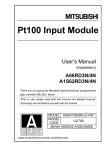
RP-SL721P and RP-SL721PF 3MP IR Bullet Network Camera User’s Manual Version 2.0 1 July 2014 Trademark Acknowledgments: All trademarks used in this handbook are registered trademarks of their respective companies. Copyright © 2014 All Rights Reserved We reserves the right to make corrections, modifications, enhancements, improvements, and other changes to its products and services at any time and to discontinue any product or service without notice. Customers should obtain the latest relevant information before placing orders and should verify that such information is current and complete. All products are sold subject to our terms and conditions of sale supplied at the time of order acknowledgment. We are not responsible or liable for the resale of its products with statements different from or beyond the specification/parameters stated by our company. Customers are responsible for their applications using our products. To minimize the risks associated with customer applications, customers should provide adequate operating safeguards. We are under no obligation to provide any further technical support service or product/software alteration beyond our representation. Our products are not authorized for use in safety-critical applications where a failure of our product would cause severe personal injury or death, unless officers of the parties have executed an agreement specifically governing such use. Reproduction of our information or datasheets with alteration is prohibited. We are not responsible or liable for any of such altered statements. Every care has been taken in editing this manual. If there are any inaccuracies or omissions, please inform our local office. We cannot be held responsible for any typographical or technical errors. We are not liable or responsible for incidental or damages caused by any misinterpretation of this publication. Contents Contents Contents iii Important Notes .................................................................................................................. v 1 Introduction 1 Hardware Overview ............................................................................................................ 2 2 Installation and Setup 5 2.1 Connecting Camera to Network through LAN Router Cable ...................................... 5 2.2 Configuring and Finding Camera via Software ........................................................... 6 2.2.1 Open the Web-based UI ............................................................................... 11 3 Camera Live View UI Settings 13 3.1 Quick Access Buttons ............................................................................................... 15 3.2 Camera Live View UI Setting Tools ......................................................................... 16 4 Setup Execution 18 4.1 System Setup Execution ........................................................................................... 18 4.1.1 Information Tab ........................................................................................... 19 4.1.2 Time Tab ...................................................................................................... 20 4.1.3 Security Tab ................................................................................................. 21 4.1.4 Maintenance Tab.......................................................................................... 23 4.1.5 System Log Tab ........................................................................................... 25 4.2 Network Setup Execution ......................................................................................... 26 4.2.1 General Tab.................................................................................................. 26 4.2.2 DDNS Tab ................................................................................................... 28 4.2.3 Multicast Tab ............................................................................................... 29 4.2.4 IP Filter Tab ................................................................................................. 30 4.3 Video & Audio Setup Execution ............................................................................... 31 4.3.1 Stream Tab ................................................................................................... 32 4.3.2 Video Tab ..................................................................................................... 34 4.3.3 Audio Tab .................................................................................................... 44 4.3.4 Privacy Mask Tab ........................................................................................ 44 4.3.5 ROI Tab ....................................................................................................... 46 4.4 Event Setup Execution .............................................................................................. 47 4.4.1 Motion Tab .................................................................................................. 47 4.4.2 Video Tab ..................................................................................................... 50 4.4.3 Snapshot Tab ............................................................................................... 54 4.5 Local Storage Setup Execution ................................................................................. 59 4.5.1 Local Storage Tab ........................................................................................ 59 Revision History 4.5.2 Playback Tab ................................................................................................ 60 5 Appendix 58 5.1 Firmware upgrade ..................................................................................................... 67 Revision History Doc. Version iv Revision Description Date 1.0 Initial Official Release 2014/04/9 2.0 Add Chapter 5 Appendix 2014/07/2 RP-SL721P and RP-SL721PF User’s Manual Read Me First! Read Me First! Important Notes This User Manual is intended for administrators and users of the RP-SL721P and RP-SL721PF IR Bullet Network Camera, including instructions for using and managing the camera on your network. The use of surveillance devices may be prohibited by law in your country or area. It is therefore the user’s responsibility to ensure that the operation of such devices is legal before installing this unit for its intended use. Before the Network Dome Camera is installed, carefully read and follow all the safety and operating instructions to avoid damage due to faulty assembly and installation. This also ensures that the device is used properly as intended. Heed All Warnings Do not drop or hit the device. Sensitive electronics inside the camera are vulnerable to excessive impact. Do not install the device under high temperature (higher than 50C) environment. Excessive heat could damage the equipment. Do not cover device with any object or install it in a poorly ventilated vicinity. Overheating could damage the camera. Do not expose the device to rain or moisture. Do not touch the power connection with wet hand. Risk of short circuit, electric shock, or fire Do not damage the power cord or leave it under pressure. Risk of fire or circuit electric shock To reduce the risk of electric shock or damage, do not open the cover except qualified person. There is no user-serviceable parts inside. Misusage, improper, or negligent handling could damage the device. Refer to qualified service personnel from our distibutor/dealer for any device related trouble shooting need. RP-SL721P and RP-SL721PF User’s Manual v Read Me First! Do not continue to operate the device if it appears to malfuntion. Contact qualified service personnel from our distibutor/dealer for help. Installation of the product should be made by qualified service personnel or system installers from our distibutor/dealer. vi RP-SL721P and RP-SL721PF User’s Manual Chapter 1 1 Introduction RP-SL721P and RP-SL721PF is a IR Bullet Network Camera featured with 3Mega Pixel resolution and superior H.264-AVC performance and rich functions. It is very suitable to view a wide/Tele area such as station, commercial, banking communication and government building, schools and airport. RP-SL721P and RP-SL721PF value-added features include; on-board video motion detection, and two-way audio. RP-SL721P and RP-SL721PF, the PoE available, full PoE (IEEE-802.3af) feature supplies power to the camera via the network, eliminating the need for power cables, reducing installation costs and complexity. Consequently, RP-SL721P and RP-SL721PF is “Best in Class” for maximum performance IP video surveillance systems, demanding superior image quality, ease of installation, and intelligent video capabilities Further functions include DI/DO alarm application and micro SD card support for local storage application. RP-SL721P and RP-SL721PF User’s Manual Introduction 1 Chapter 1 Hardware Overview 2 Introduction RP-SL721P and RP-SL721PF User’s Manual Chapter 1 RP-SL721P and RP-SL721PF provide extra connections with outside devices via water proven RJ45 connector. User can make the connectors to support 1) Video Out, 2) Audio In, 3) Audio Out, 4) Terminal Block for GPIO. Please refer to following table of the pins definition of RJ45: RP-SL721P and RP-SL721PF User’s Manual 3 Introduction Chapter 1 Pin Function 1 DO_COM 2 DO_NO Description Digital Output: each digital output pin to COM (Pin1) is a photo-coupled relay on Normal Open status. External device can directly connect to the terminals. However the current that will go through the 2 nodes must not exceed 130mA. An external “Relay” can also be connected to the terminals as an implementation. In this case, current (or/and voltage) limitation is specified by the external Relay. Digital Input: Only one set is designed in this Camera Model. The internal device is also photo-coupled electrical relay; and the external device can be simply an On/Off switch. Each set of On/Off switch can be connected as one trigger source. 3 DI 4 GND 5 Default Setting Default Setting: Short Pin4 and Pin5 with a wire PIN with a short wire to revert to factory default settings. Break the short when the LED starts quick flashing, and then camera will reboot automatically a few minutes later. 6 7 8 Audio In Audio Out CVBS Out Don’t forget to connect Audio In / Audio Out / CVBS Out GPIO Pin to GND for active; or leave floating (or unconnected) to deactivate. 4 Introduction RP-SL721P and RP-SL721PF User’s Manual Chapter 2 2 Installation and Setup 2.1 Connecting Camera to Network through LAN Router Cable Power Adapter Figure 2-1 Connecting IP Camera to Network 1. Prepare a PC/notebook/ultrabook with Ethernet link to the network. 2. When PC/notebook is used, connect the LAN port of the device to the network router with an RJ45 network cable ( ). 3. Plug the DC power jack of the power adaptor ( ) to power jack on the extension cable of Camera and connect the power adaptor to power outlet (110V or 220V). 4. Connect the network router to the LAN port on the extension cable of Camera with an RJ45 network cable (). 5. With power switched on a few minutes later, you should find out this camera via CAM FINDER utility in CD. RP-SL721P and RP-SL721PF User’s Manual Installation and Setup 5 Chapter 2 2.2 Configuring and Finding Camera via Software You could find CAM FINDER utility from the attached Software Package CD. The CAM FINDER is used to find and configure network cameras on the LAN. This utility is useful for conveniently configuring the network settings of the device, or for finding a device once the network settings have been modified. To install the CAM FINDER, from the Software Package CD, select CAM FINDER, then follow the instructions to complete the installation. NOTE 1. In order to ensure Camera will be assigned IP Address properly, please confirm the following things. Always consult your network administrator in order to avoid using a previously assigned IP address. Check if the Camera is powered on and correctly connected to the network. In order to connect to the Web-based user interface of the camera, the host PC must be in the same subnet. For more information about subnets, please consult your network administrator. 6 Installation and Setup RP-SL721P and RP-SL721PF User’s Manual Chapter 2 1. Once CAM FINDER has been successfully installed on the PC/notebook/ultrabook, double click Mouse left button to run the software. 2. Click the [Device Search] to search the device in the LAN. Figure 2-2 Find the Camera Device via “Device Search” button 3. Under your selected item, double-click the left Mouse button or Right-click the Mouse button to open the Property Page item [Single Device Setting]. Figure 2-3 Open the Camera’s Property setting page via “Single Device Setting” item RP-SL721P and RP-SL721PF User’s Manual 7 Installation and Setup Chapter 2 4. Check [Static IP address] or [Use DHCP Service] item to select the network connection method of the camera. Figure 2-4 Enter the Camera Device’s network setting manually. Figure 2-5 Check “Use DHCP Service” item to let camera get IP Address automatically. 8 Installation and Setup RP-SL721P and RP-SL721PF User’s Manual Chapter 2 5. After modifying the camera properties, click [Set] button to save and enable the configuration modifications. Figure 2-6 Click “Set” button to save and enable the modification. RP-SL721P and RP-SL721PF User’s Manual 9 Installation and Setup Chapter 2 6. Use“Ctrl”or“Shift”key on the keyboard to choose several Camera Devices. Then click the [Batch Device Setting] to configure them together. Figure 2-7 Select multi-Camera Devices and then configure their properties together via “Batch Device Setting” item Figure 2-8 Check “Increase IP” setting to set Camera Device’s IP address increasing one by one. Then click “Set” button to save and enable the modification. 7. [Language] support for Chinese, English and Spanish. Figure 2-9 Selecting “Language” item could change the displayed language font of CAM FINDER utility. 10 Installation and Setup RP-SL721P and RP-SL721PF User’s Manual Chapter 2 2.2.1 Open the Web-based UI 1. To access the Web-based UI of the selected unit, run the [Open Web] on the select item. Figure 2-10 Open the Camera’s Web-based UI Page via “Open web” item 2. For first time user, there will be a prompt to install the ActiveX control. Comply with the ActiveX installation as they are needed to view the video stream and some other operations. Besides, use of Microsoft IE browser is recommended as it offers a better compatibility. Figure 2-11 ActiveX components are required for Camera’s Live Stream and configuration operation. ※ Please also note to close all browser applications before NetcamViewer web component installation. RP-SL721P and RP-SL721PF User’s Manual 11 Installation and Setup Chapter 2 3. If the camera and browser components have been configured correctly, the default Web browser will open to the Live View page of the selected camera. * Username and password is required to enter “SETUP” Webpage. (Default is admin / admin) Verify and Complete the Installation from Your Browser If your IE Browser can’t get the ActiveX download properly, you may have to temporarily lower your security settings to perform a one-time-only installation of the ActiveX component onto your workstation, as described below: 1. From the IE Browser menu, select [Internet Options] -> [Security] -> [Custom Level] 2. Set the security level to Low and click [OK]. 3. Don’t forget to restore the security level after the ActiveX installation. 12 Installation and Setup RP-SL721P and RP-SL721PF User’s Manual Chapter 3 3 Camera Live View UI Settings Using PC/notebook/ultrabook, you may change and reconfigure the Camera live view user interface (UI) settings to suit your need by following the procedures below. 1) Execute your Web Browser and then manually enter the Camera Device’s IP address gotten via CAM FINDER utility. NOTE For first time user, there will be a prompt to install the ActiveX control. Conply with the ActiveX installation as it is needed to view the video stream and some other operations. Use of Microsoft IE browser is recommended as it offers a better compatibility. 2) Then the “Windows Security” dialog displays. Enter a username and password. You may enter “admin” for both. Click OK button when completed. (Note that same Browser with different version or different vendor Browser will behave different dialog window. Below picture is belonging to IE Browser’s diagram.) Figure 3-1 “Windows Security” Dialog RP-SL721P and RP-SL721PF User’s Manual Camera Live View UI Settings 13 3) The “Live View Setting” window will then display offering all the necessary set up tools for changing the live view reconfigurations. The functions of each of these tools are explained in the following sections. Figure 3-2 Camera “Live View Setting” Window Chapter 3 3.1 Quick Access Buttons The following buttons provide the basic interactive functions between the Camera and the host computer as described below. Figure 3-3 Camera Quick Access Toolbar Buttons Mute: Turn On/Off the host computer speaker. Talk: Click this button to enable/disable talk function to someone facing the network Camera from your computer. For ideal voice reception, the distance of the person on view, should be kept within 2 meters from the Camera. Snapshot: Click this button to capture still images taken from the Camera and save them in the host computer. Recording: Click this button to record live video clips from the Camera into your computer. Digital Zoom: Digital “zoom in” & “zoom out” of a particular area of the live view. To display the whole live view into full screen, double click on the video. RP-SL721P and RP-SL721PF User’s Manual Camera Live View UI Settings 15 3.2 Camera Live View UI Setting Tools Actual Size: Click actual size to view actual size of Image Protocol: Option for TCP, UDP or HTTP transmission protocol with H.264/MPEG4 streaming is available. Video Stream: Two simultaneous streaming is supported for live viewing. Click Browse button to define Recording Path and Recording Filename for the video you are preparing to record. Recording Path: Specify a storage destination path for the video you are going to record. Recording file name: Define a base filename for the video recordings you are going to take. The base filename will auto-expand for each saved video recording. To start recording, click the Recording button. Click Browse button to define Snapshot Path and Snapshot Filename for the snapshots you are preparing to capture. Snapshot Path: Specify a storage destination path for the snapshot images you are preparing to capture. Snapshot file name: Define base filename for the snapshots you going to capture. The base filename will auto-expand for each saved snapshot. To start capturing snapshots, click the Snapshot button. Click Setup button to change or update more Camera settings. Setting Language: Select the default language of the user-interface. Chapter 3 As you get familiar with features and functions of your Camera, you may want to change or update a number of its settings to further upgrade its performance. This can be accomplished by clicking the Setup button (indicated in the above figure). The Setup dialog (see following figure) will then display to provide the range of setup categories you will be able to change. Figure 3-7 Camera Setup Dialog RP-SL721P and RP-SL721PF User’s Manual Camera Live View UI Settings 17 4 Setup Execution Figure 4-1 Camera Setup Selection Buttons NOTE For “Live View” setup execution, please refer to the previous chapter “Camera Live View UI Settings” 4.1 System Setup Execution Clicking the System button will display the following tabbed panes relative to system configurations. Figure 4-2 “System Setup” Tabbed Panes RP-SL721P and RP-SL721PF User’s Manual 4.1.1 Information Tab ` Figure 4-3 “Information” Tabbed Pane The Information tabbed pane provides the existing system status of the Camera which includes Model Name, System Time, Firmware Version, MAC Address, ActiveX Control Version, Wired Network, Wireless Network and DDNS Server Status. RP-SL721P and RP-SL721PF User’s Manual 4.1.2 Time Tab Figure 4-4 “Time” Tabbed Pane The Time tabbed pane is where you set up the clock of your Camera to synchronize with your local time. Where: System Time: The Network Camera current date and time is applied and displayed here based on the setup status of the System Time Settings as detailed below. Time Zone: Select the applicable Time Zone of your city in reference to Greenwich Mean Time. Automatic: Select this item if you want to automatically synchronize the Camera clock with your manually entered Network Time Protocol (NTP) Server. RP-SL721P and RP-SL721PF User’s Manual Keep current date and time setting: Select this option in lieu of automatic synchronization if the Camera is not connected to NTP Server and uses its own embedded clock. Set Manually: Synchronize with the computer Time: Select this option to manually synchronize the Network Camera clock (date and time) with that of the local host computer. Assign value: Select this option to enter the date and time manually. Enable Daylight Saving: Select this option only when applicable at your location. Two setup settings; the Start time and End time are needed to implement the feature. After setups are completed, click Save button to apply the settings. 4.1.3 Security Tab This is a permanent default setting and cannot be removed nor changed. Hence, new User Name/Group settings are only added below the default setting Click Add button to access and change the security setting status Figure 4-5 “Security” Tabbed Pane The Security tabbed pane allows you to add new Camera User Name and change Password and the surveillance status or User Group. Click the Add button to access the security setup dialog (shown below). RP-SL721P and RP-SL721PF User’s Manual Figure 4-6 “Security” Setup Dialog Where: User Name: Enter the new user name to be added into the list (see Note 4 of dialog for proper entry). Password: Enter the new password (see Note 4 of dialog for proper entry). Confirm password: Enter the password again for authentication (encoded display). Show Password: Displays the decoded password when check box is enabled. User Group: Three group options are available, namely: Administrator: User is allowed to change Camera settings and perform all Camera functions. Operator: User is allowed to login “Live View” Webpage and perform all functions within this page. Except changing Video and Audio settings of Camera live stream, other adjustments of Camera parameter are prohibited. Viewer: User is only allowed to login “Live View” Webpage and perform all functions within this page. Changing Camera settings is prohibited. After setups are completed, click Save button to apply the settings. RP-SL721P and RP-SL721PF User’s Manual 4.1.4 Maintenance Tab Download and save the latest firmware in the PC Click here to browse and select it. Figure 4-7 “Maintenance” Tabbed Pane The Maintenance tabbed pane allows you to upgrade the firmware with the latest version and to restore the Network Camera settings to factory default. Where: Upgrade Firmware: Download the latest firmware file from the website by executing the following steps: 1) Click the Browse button to access and select the appropriate firmware file from its folder. 2) Click the Upgrade button. The Network Camera will then start to upgrade the existing firmware. When upgrade is completed, the Camera will reboot automatically. Upload Own Logo File: Prepare and save the Logo Image file in the PC. Then Follow the below steps to replace Web UI Logo with it. RP-SL721P and RP-SL721PF User’s Manual Backup: Upload Setting: 1) Click the Browse button to access and select the Logo Image file from the PC. 2) Click the Upload button to process Logo replacing. When upload process is completed, it’s strongly recommended to close and restart Web Browser. Clicking the Backup button allows you to manually save Camera’s parameters and user settings into a config_backup.tar.gz file. This function allows user to restore Camera’s backup setting by executing the below steps: 1) Click the Browse button to access and select saved config_backup.tar.gz file from the PC. 2) Click the Restore button to process Camera configuration restore. Reboot System: Clicking the Reboot button allows you to manually reboot the Network Camera. Restore System: Clicking the Factory Default button will restore the Network Camera to its factory default settings status. Before Camera system proceed to restore step, there’ll be a dialog window popped and then ask if you would like to keep “Network setting” parameters. Besides, all configured data in the “System Time”, “Security” and “Maintenance” tab will be remained current. RP-SL721P and RP-SL721PF User’s Manual 4.1.5 System Log Tab Click it; There will be another browser page opening and then displaying Camera’s basic log. Figure 4-8 “System Log” Tabbed Pane The System Log tabbed pane allows you to see Camera’s basic log on another browser page or Remote Log Server. Where: Remote Log Settings: Check “Enable remote log” selection first; and then manual entering IP address & port setting of Remote Log Server. After setups are completed, click Save button to apply the settings. RP-SL721P and RP-SL721PF User’s Manual 4.2 Network Setup Execution Clicking the Network button will display the following tabbed panes on configuring Camera connection with the network. Figure 4-8 “Network Setup” Tabbed Panes 4.2.1 General Tab The General tabbed pane (shown above) allows you to redefine the network and port protocol settings of the Network Camera. Where: Network Settings: DHCP: This option obtains the available dynamic IP address assigned by the DHCP server each time the Camera is connected to the network. Fixed IP Address: This option manually assigns a static IP address to the Network Camera. RP-SL721P and RP-SL721PF User’s Manual PPPoE: Select this option to set PPPoE account & password. While PPPoE protocol is selected, you may have to enter some more information such as the above picture. While Camera IP is changed dynamically because of PPPoE Network Connection, its new IP Address will be sent to “Sender E-mail Address” through SMTP service. So you won’t worry about the difficulty in Camera’s Webpage access. ※ As for the settings of SMTP Service, kindly please contact with your E-mail service provider。After you confirm all parameters are correct and working properly, you may enter them into the text area manually. Port Settings: HTTP Port: Re-define the existing HTTP Port number in the text box. RTSP Port: Re-define the existing RTSP Port number in the text box. After setups are completed, click Save button to apply the settings. RP-SL721P and RP-SL721PF User’s Manual 4.2.2 DDNS Tab Enabled check box to display password in decoded format Figure 4-10 “DDNS” Tabbed Pane The DDNS tabbed pane allows you to configure the Dynamic Domain Name System of your network device with a host name instead of the IP Address. Where: DDNS Enable: Enable the check box to support DDNS function. Host Name: Enter the Host name which you registered and got through DNS Service Provider. The assigned host name is used to access the network device instead of IP Address. User Name/Password: Account authentication for logging into the website of DNS Service Provider. Update Time: Define a time interval for the device to periodically update and check its access status with website of DNS Service Provider. After setups are completed, click Save button to apply the settings. RP-SL721P and RP-SL721PF User’s Manual 4.2.3 Multicast Tab Check the “Enable” box to open UDP Multicast Streaming function of stream1, 2 or 3. Figure 4-11 “Multicast” Tabbed Pane The Multicast tabbed pane allows you to open Camera’s UDP Multicast Streaming function. By default, Camera’s live stream belongs to RTSP Protocol. It means camera has to send an individual streaming for each client wish to see the videos. So the more the client number is, the larger the network bandwidth required and the bigger loading of the camera. In other words, the camera can send just one streaming and each client can receive the streaming with Multicast Protocol. Even with the client number increasing, the network bandwidth is still the same loading with one camera. After checking the “Enable” box to open this function, click Save button to apply the settings. RP-SL721P and RP-SL721PF User’s Manual 4.2.4 IP Filter Tab After clicking Add button, there will be IP address input field expanding. Figure 4-12 “IP Filter” Tabbed Pane The IP Filter tabbed pane could let you configure device IP list which is denied access to this camera. Where: Start IP address: Fill in the first address of IP range which you would like to deny its access to camera. End IP address: Fill in the last address of IP range which you would like to deny its access to camera. ※ please note that total devices which are denied to access would be limited to 20. Filling the IP range, then click Save button to implement the settings. If you would like to re-open the access right of those listed device, select it from the list and then click Remove button to apply the settings. RP-SL721P and RP-SL721PF User’s Manual 4.3 Video & Audio Setup Execution Clicking the Video & Audio button will display the following tabbed panes for defining Camera streaming, video, and audio functions. Figure 4-11 “Video & Audio” Tabbed Panes RP-SL721P and RP-SL721PF User’s Manual 4.3.1 Stream Tab The Stream tabbed pane (see above figure) provides the adjustments for the video quality of the Camera streaming function. The pane offers the following three modes of video quality setting: Video quality settings for stream 1: This is the primary quality setting for live view streaming. Video quality settings for stream 2: This is the secondary quality setting for live view streaming. Video quality settings for stream 3 : This is the secondary quality setting for live view streaming. NOTE If the “Video Event Alarm Setting by Video” (see Section 4.4.2) is enabled, an alert message will display requiring you to disable the feature first before proceeding to change the Streaming settings. Otherwise, adjustments to video quality streaming settings cannot be accomplished. The quality setting items on this pane are as follows: Connection template: Four option modes are available; “Fast,” “General,” “Low,” and “Customized” modes. Mode: Three modes of encoding options are offered; “H264,” “MJPEG,” and “MPEG4.” Frame Size: Three 3 types of streamed frame resolutions are available to selection; “2048x1536,” “1920x1080,” and “1600x1200” Maximum Frame Rate: Available rate options are; 1, 2, 3, 5, 8, 10 & 15 frames per second (FPS), 1080P Full HD available for 30 FPS Steaming Mode: Two choices of streaming modes are offered; “VBR (variable bit rate)” and “CBR (constant bit rate).” Quality: VBR: Bitrate: CBR: The options for streaming mode quality are expressed differently between VBR and CBR: Standard, Good, & Detailed 64K bps, 128K bps, 256K bps, 384K bps, 512K bps, 768K bps, 1M bps, 1.5M bps, 2M bps, 3M bps, 4M bps, 5M bps, 6M bps, 8M bps, 10M bps and 12M bps. RP-SL721P and RP-SL721PF User’s Manual Intra frame period: Available choices are; 5, 8, 10, 15, 20, 25, 30, 40, 50 & 60 frames per period. This function will let you choose how long distance between two I-Frames. Lager value means longer distance between two I-Frames and this selection is suitable for the stable Network Bandwidth Environment; so we suggest the smaller value selection is proper to the worse Network Bandwidth Environment. Text Overlay: When enabled, each streamed frame will be overlaid with the Camera ID (text field) and stamped with date/time (if enabled) as illustrated below. Figure 4-12 Text Overlay Setting Example RTSP Port Access Name: When RTSP or VLC media-player is used, the port can be renamed with easy to remember pathname. For example: the de Default RTSP Port Access Name is live1.sdp;it means your stream name would be “RTSP://camera’s IP address/live1.sdp” After setups are completed, click Save button to implement the settings. RP-SL721P and RP-SL721PF User’s Manual 4.3.2 Video Tab Figure 4-13 “Video” Tabbed Pane RP-SL721P and RP-SL721PF User’s Manual The Video tabbed pane lets you to perform live adjustments and improvement of the Camera captured video effect relative to the target environment. Where: Template: That means you can select what environment to use for base on your scenario. There are four kinds of template to choose. General/Outdoor/WDR/Night Speed Mode Brightness: The luminance of the captured image apart from its hue or saturation. Try to assign the fit value according to the environment Adjust the Brightness value to 100. Saturation: The degree of intensity and purity of a specific color. Try to assign the fit value according to the environment. Adjust the Saturation value to 200. RP-SL721P and RP-SL721PF User’s Manual Contrast: The brightness ratio of the lightest to the darkest part of the video image. Try to assign the fit value according to the environment. Adjust the Contrast value to 100. Sharpness: Sharpness can be defined as edge contrast. So when we increase sharpness, we increase the contrast only along/near edges. Try to assign the fit value according to the environment. Adjust the Sharpness value to 0. Adjust the Sharpness value to 200. RP-SL721P and RP-SL721PF User’s Manual EV Compensation: Exposure Compensation is a feature of a camera that allows you to adjust the exposure value manually. You may increase or decrease the amount of brightness or darkness of your picture through sliding the bar. Try to assign the fit value according to the environment. Adjust the EV Compensation value to 50. Adjust the EV Compensation value to 200. Pre-Noise Reduction & 2D Noise Reduction: Both of them are one kind of technology to provide clearer video with less noise under poor lighting conditions, making it easier to identify people or objects. Try to set them according to the stream quality. RP-SL721P and RP-SL721PF User’s Manual Wide Dynamic Range: Enable this function could let camera provide clear images even under backlighting. Set WDR function to Disable. Set WDR function to Enable. RP-SL721P and RP-SL721PF User’s Manual White Balance: Because camera doesn’t have ability to automatically adjust different color (temperature) to the environment, six templates are provided to let you choose for different light. Day/Night Threshold: Set the illumination lux value (5 ~ 100) to auto-trigger the Camera into “day” or “night” mode relative to luminance of the area under surveillance. When the environment luminance becomes higher than the set lux value, the Camera will auto switch to “day” or “color” mode. Otherwise, it will remain at “night” or “mono” mode with IR. Camera switches to Night or Mono mode with IR on. Video Orientation: rotate the image, so it looks up-side down. This can be applied when camera unit must be ceiling mounted and the image is therefore reversed Night speed mode(LPR): Video setting page to select Night Speed Mode RP-SL721P and RP-SL721PF User’s Manual Because the shuttle speed is 1/480 second for this mode, so the whole picture is very dark at night. (Snapshot without extra light compensation as following) ※Fixed Lens: RP-SL721PF equipped fix focal and fix aperture lens, it can only identify license plate of vehicle at speed under 40 km/hr in single lane view. ※Vari-focal Lens: RP-SL721P equipped vari-focal and auto-IRIS lens with larger aperture that can identify license plate up to 60 km/hr in double lane view. ※Without extra IR projector at night, the recognition condition of license plate snapshot by vari-focal lens model is better than fix lens model. For example: License plate snapshot by fixed lens with license plate light RP-SL721P and RP-SL721PF User’s Manual License plate snapshot by vari-focal lens with license plate light in outside lane of double-lane road Vari-Focal Lens RP-SL721P license plate night view: with and without license plate light Without license plate light With license plate light RP-SL721P and RP-SL721PF User’s Manual Fixed Lens RP-SL721PF License Plate Night View: without or only one license plate light Without license plate light Only one license plate light Vari-Focal RP-SL721P license plate day view: vehicle at outside lane RP-SL721P and RP-SL721PF User’s Manual Fixed Lens RP-SL721PF license plate day view RP-SL721P and RP-SL721PF User’s Manual 4.3.3 Audio Tab Figure 4-15 “Audio” Tabbed Pane The Audio tabbed pane provides the following audio adjustments to your Camera Audio-In port: Mute: Enable or disable mute function of the Camera’s Audio-In signal. Volume: Plug an audio source device into the Audio-In port of camera. And its playback volume could be adjusted by moving the slider to the left to decrease; and to the right to increase the volume. After setups are completed, click Save button to implement the settings. 4.3.4 Privacy Mask Tab 3) Enable the check box This is an “Ellipse” type. This is a “Line” type. 2) Lay out masking screens on the areas to be blocked from surveillance 1) Select a masking shape to block the private area you wish to obstruct from surveillance 4) Click Save button This is a “Rectangle” type. Figure 4-16 “Privacy Mask” Tabbed Pane RP-SL721P and RP-SL721PF User’s Manual The Privacy Mask tabbed pane allows you to mask or block private areas from surveillance for privacy reason. To block a private area from surveillance, follow the procedure below: 1) Initially select the masking shape, e.g., “Line,” “Rectangle,” or “Ellipse” (see figure above) you wish to use as screen to block the area from surveillance. 2) Click and drag the mouse cursor to lay out a masking screen on the area you wish to block, and then release the mouse right button. Notice that the laid out screen turns into phantom block. 3) If the laid out screen needs correction, click Delete button and redo the masking screen lay out process. 4) Once the masking screen is acceptable, click the Enable Privacy Mask check box followed by clicking of the Save button. This will turn the laid out screen into solid block. To disable masking and remove the screen, do the following: 1) Click Delete button. 2) Click Save button and wait a while. Then the screen is permanently removed. 2. Then click the “Save” button and wait the state finished. 1. Please click “Delete” button. Figure 4-17 Removing “Privacy Mask” Screen from Camera 3) To permanently disable the Privacy Mask function, disable the Enable Privacy Mask check box RP-SL721P and RP-SL721PF User’s Manual 4.3.5 ROI Tab When network capacity is constrained , or there is simply a desire to improve network usage efficiency and storage, clicking the ROI button will display the tabbed panes (see figure below) for defining enhance video quality area of the camera. Defining a single ROI detection area: 1) Enable the Enable check box. 2) Click Add button and a default frame will pop-up on the screen. 3) Click and hold inside the frame to drag it to the location where you want to focus detection. Resize the frame by dragging its corners or borders. 4) Click the Save button to apply. ※only support H.264 1. To enable “ROI” function. Enhance video quality of ROI. 2. To draw a region to define the detection range. Figure 4-18 Defining a Single ROI Area for the Camera Defining multiple ROI detection areas: 1) After satisfactory positioning of the first detection area as described above, click the Add button again. A second default frame will pop-up on the screen. Drag & resize the frame at the desired location. 2) Repeat the above step to add more detection area frames. RP-SL721P and RP-SL721PF User’s Manual Figure 4-18-1 Defining multiple ROI Areas for the Camera 4.4 Event Setup Execution Clicking the Event button will display the tabbed panes (see figure below) for defining event recording of the Camera. The RP-SL721P and RP-SL721PF is equipped with a card slot for Micro-SD/SDHC memory card. This storage card is utilized to store recording of local video and still JPEG images taken in response to set events. The recording operation of events is triggered according to the defined schedules. 4.4.1 Motion Tab From the Motion tabbed pane, you can define specific target areas within the scope of surveillance to focus the motion detection function. RP-SL721P and RP-SL721PF User’s Manual 1. To enable “Motion Detection” function. 2. To draw a region to define the detection range. Figure 4-19 Defining a Single Motion Detection Area for the Camera Defining a single motion detection area: 1) Enable the Enable Motion Detection check box. 2) Click Add button and a default frame will pop-up on the screen. 3) Click and hold inside the frame to drag it to the location where you want to focus detection. Resize the frame by dragging its corners or borders. 4) Click the Save button to apply. RP-SL721P and RP-SL721PF User’s Manual Defining multiple motion detection areas: 1) After satisfactory positioning of the first detection area as described above, click the Add button again. A second default frame will pop-up on the screen. Drag & resize the frame at the desired location. 2) Repeat the above step to add more detection area frames. NOTE Total defined motion detection areas cannot exceed 10 frames. Figure 4-20 Defining Multiple Motion Detection Areas for the Camera 3) To assign unique names to each framed location for easy identification, click on the frame and a Window Name text box with the default name of the selected frame, will appear at the bottom of the pane (see figure below). Enter a new name and click the Save button. Wait for a while for the change to take effect. Figure 4-20 Detection Frame “Window Name” Textbox RP-SL721P and RP-SL721PF User’s Manual 4) To delete a frame that is no longer needed but was previously saved, click on the unwanted frame and click Delete button. The frame will disappear after a while. 5) To delete multiple frames that are not yet saved, directly click the Refresh button instead of deleting them individually. The Refresh button will automatically clears all unsaved frames. 4.4.2 Video Tab The Video tabbed pane sets the video recording trigger method to use when motion is detected by the Camera. The four methods available for selection are Period, Schedule, Motion, and GPIO Input, each of which can be set up with user scheduled recoding time and duration, as well as defining the video record file target destination. Period: This method will trigger the Camera video surveillance/recording operation for a defined duration (in seconds) whenever motion is detected. The video record may be provided to host by E-mail/FTP, stored in the SD card, Remote Disk as selected or through all of them. Figure 4-21 Video Recording with “Period” Method Selected RP-SL721P and RP-SL721PF User’s Manual Schedule: This method activates the Camera video surveillance/recording operation continuously when the defined days of the week and set time of the set days are met. Motion is ignored with this method. Each recording time-span is in accordance with the set duration (in seconds) and the video record is stored in the SD card, Remote Disk as selected or through both of them.. Figure 4-22 Video Recording with “Schedule” Method Selected RP-SL721P and RP-SL721PF User’s Manual Motion: This method will trigger the Camera video surveillance/recording operation according to the set duration (in seconds) whenever motion is detected within the defined days of the week and at the time of the set days. The video record may be provided to host by E-mail/FTP, stored in the SD card, Remote Disk as selected or through all of them. Figure 4-23 Video Recording with “Motion” Method Selected RP-SL721P and RP-SL721PF User’s Manual GPIO Input: On the defined days of the week and at certain time of the set days, the Camera will trigger its GPIO Input Signal when its state changes. Recording duration can be set in seconds and the video record may be provided to host by E-mail/FTP, stored in the SD card, Remote Disk, activated GPIO Output Port or through all of them. Figure 4-24 Video Recording with “GPIO Input” Method Selected RP-SL721P and RP-SL721PF User’s Manual 4.4.3 Snapshot Tab The Snapshot tabbed pane sets the Camera to take snapshot images when motion is detected. The four methods available for selection are Always, Schedule, Motion, and GPIO Input, each of which can be set up with user scheduled recoding time and duration, as well as defining the video record file target destination. Always: Under this method, the Camera automatically continuous to capture 6 snapshots of the area under surveillance at every 1 or 2 seconds interval. 3 previous snapshot frames are collected from the Camera buffer and 3 snapshot frames are captured live. The stream of accumulated snapshots may be sent to host by E-mail, FTP, stored in the SD card, Remote Disk as preferred or through all of them. 6 snapshots are continuously collected at every 1 or 2 seconds interval. Figure 4-25 Snapshot Recording with “Always” Method Selected RP-SL721P and RP-SL721PF User’s Manual Schedule: This method activates the Camera snapshot operation continuously when the defined days of the week and set time of the set days are met. The Camera will continuously capture 6 snapshots of the area under surveillance at every 1 or 2 seconds interval. 3 previous snapshot frames are collected from the Camera buffer and 3 snapshot frames are captured live. The stream of accumulated snapshots may be sent to host by E-mail, FTP, stored in the SD card, Remote Disk as preferred or through all of them. Figure 4-26 Snapshot Recording with “Schedule” Method Selected RP-SL721P and RP-SL721PF User’s Manual Motion: This method will trigger the Camera snapshot operation according to the set time interval (in seconds) whenever motion is detected within the defined days of the week and at the time of the set days. Single or 6 snapshots may be captured as defined. The stream of accumulated snapshots may be sent to host by E-mail, FTP, stored in the SD card, Remote Disk as preferred or through all of them. User could select “Single” or “6 snapshot…” Figure 4-27 Snapshot Recording with “Motion” Method Selected RP-SL721P and RP-SL721PF User’s Manual GPIO Input: On the defined days of the week and at certain time of the set days, the Camera will trigger its GPIO Input Signal according to the set time interval (in seconds) when its state changes. Single or 6 snapshots may be captured at a time as defined. Figure 4-28 Snapshot Recording with “GPIO Input” Method Selected The stream of accumulated snapshots may be sent to host through E-mail, FTP, stored in the SD card, Remote Disk, activated GPIO Output Port; per selection or through all of them. When selected, the setup dialog for these methods will display is illustrated in the following figure. RP-SL721P and RP-SL721PF User’s Manual Figure 4-29 Transmitting Snapshots to Host Setup with “E-mail” & “FTP” Selected ※ As for the settings of SMTP Service, kindly please contact with your E-mail service provider。After you confirm all parameters are correct and working properly, you may enter them into the text area manually. ※ As for the settings of FTP Service, kindly please contact with your FTP service provider。While all parameters filled in Windows FTP Transferring Utility are correct and working properly under your Laptop or other PC, you may enter them into the text area manually. RP-SL721P and RP-SL721PF User’s Manual 4.5 Local Storage Setup Execution Clicking the Local Storage button will display the following tabbed panes to provide information on existing local storage, such as disk size info, type, and status. If recording is in progress when clicking the Local Storage button, a warning message will occur. NOTE Do NOT remove the micro SD card while Camera is in recording process. 4.5.1 Local Storage Tab The Local Storage tabbed pane displays the SD card status. It shows the SD card total capacity (Total size), available memory (Free size), used memory (Used size) and used memory ratio (Use(%)). It also display the current Camera operation condition (Recording status) and provide “SD card control” option where user can select to allow the Camera to auto-overwrite earlier files in order to maintain the defined “Keep Free Space” memory size. Enable check box to allow auto-overwrite of earlier files in order to maintain the defined “Keep Free Space” memory size Figure 4-30 “Local Storage” Tabbed Pane : Click this button to save changes to the SD card control setting. : Click this button to format the SD memory card (take note of the message in red). : Click this button to refresh the SD card information. RP-SL721P and RP-SL721PF User’s Manual 4.5.2 Playback Tab The Playback tabbed pane allows user to playback video and snapshot files stored in the SD memory card. These files were saved using the Event setup for video (see Section 4.4.2) and snapshots (Section 4.4.3) with the SD card check box enabled. Playback of the stored videos or snapshots is performed from files recorded on particular date range as explained in the following figure. 1) Select type of files to playback 2) Search for the files to playback by defining the files recording date range 3) Click Search button and the files recorded within the date range will display below 4) Select the file to playback and enable the corresponding check box. The dialog strip below will then pops up. 5) Clicking Open button will playback the file. Save button will save file to a designated folder. Figure 4-31 “Playback” Tabbed Panel RP-SL721P and RP-SL721PF User’s Manual 5 Appendix 5.1 Firmware Upgrade This section mainly will instruct you how to update camera firmware step by step. 1. Find the camera and open its Web-based UI via CamFinder utility – Chapter 2.2. ※ Below are the tips to let you understand how to solve NetcamViewer installation problems more easily. If below picture is always popped even NetcamViewer is downloaded and installed successfully in your PC. Please help to check if your IE Browser version is 11 first. If it is yes, kindly please help to refer the below steps to enable Compatible View settings of IE 11 Browser. RP-SL721P and RP-SL721PF User’s Manual Find Tools icon and then select Compatibility View settings. Or RP-SL721P and RP-SL721PF User’s Manual Click Add button to add camera webpage as a compatible website. After successful adding, camera webpage should be set as compatible view website. RP-SL721P and RP-SL721PF User’s Manual Then camera webpage would be refreshing real-time and starting to load camera webpage. Click Allow button to enable NetcamViewer component running… Manual entering camera’s username/password to pass authentication. RP-SL721P and RP-SL721PF User’s Manual Camera live stream is successful playing in IE11 Browser If error message “opening file for writing C:\Windows\sytem32\LibPMD.dll” is always popped during NetcamViewer installation, kindly please turn of all browser windows, include CDWizard application and then try NetcamViewer installation again. So before NetcamViewer installation, please make sure there’s no iexplore process running in Windows Task Manager Window. If there is ie explore process existing, select “End Process” to force its stop. RP-SL721P and RP-SL721PF User’s Manual During NetcamViewer installation, you may see below prompt windows are always popped. This will mainly remind you to close all running browser applications and then press “OK” button to continue NetcamViewer installation. Or these two windows will pop continuously until all browsers are closed. RP-SL721P and RP-SL721PF User’s Manual 1. Manual input username admin, password admin to pass login authentication of camera webpage. 2. After Live View page is entering successfully, find the “SETUP” button. Clicking it could change or update more Camera settings. – Page 18. RP-SL721P and RP-SL721PF User’s Manual 3. Find Maintenance Tab of Camera Setup Webpage. – Chapter 4.1.4. 4. order to have the best performance with Camera, kindly please ask for distributor/dealer’s help to get the latest firmware version downloading. 5. After downloading it, click the Browse button to open below dialog for firmware choosing. Select the appropriate firmware file from its folder in PC and then click Open button to choose it. RP-SL721P and RP-SL721PF User’s Manual [※ Please specify the correct firmware version mapped with your camera to upgrade, or there will be danger to damage camera system.] 6. Click the Upgrade button and then one prompt window will pop to tell you “wait about 30 seconds to stop all processes!” 7. Click the OK button to exit the window. Then you will see Camera Webpage is reloading, it means all processes of camera are stopping at the same time. RP-SL721P and RP-SL721PF User’s Manual 8. After all processes are stopped, the camera will start to upgrade the firmware you chose. 9. Please don’t power off camera or do any unnecessary jobs during firmware upgrade. Until the process goes to 100%, there will be messages popped to suggest you restart the Web Browser. 10. While the OK button is clicked, the camera webpage connection will be closed. And then you have to re-login again. RP-SL721P and RP-SL721PF User’s Manual 11. After camera Web-based UI is re-login successfully, go to Information Tab of Camera Setup Webpage to check if the firmware version is different with before; or check if the firmware version is the same with distributor/dealer provided. – Chapter 4.1.1 RP-SL721P and RP-SL721PF User’s Manual