1
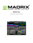
2
INTRODUCTION
6
INSTALLING THE SOFTWARE – PC
6
INSTALLING THE SOFTWARE – MAC
6
ABOUT YOUR LICENSE
7
Obtaining your serial number from the Media Fusion web site
7
Preparing your Machine ID code
Generating your final serial number
7
7
Connecting a DMX console to Media Fusion
8
General Concept
8
1. Setting up your Robe Media Fusion DMX USB device on a PC
2. Setting up your Robe Media Fusion DMX USB device on a Mac OSX
9
9
INTRODUCTION TO THE SOFTWARE
10
Basics
10
Overview
11
Features summary
11
Driving LED panels
12
USING THE SOFTWARE
13
The main window
13
a. Previews area
b. The master output area
c. Layer parameter area
13
14
14
Media management
18
Basics
Media Library Dialog
Building your libraries
File system
18
19
20
21
Text Library
22
3
The preferences dialog
24
The Display tab
The DMX tab
The Performances tab
The LED Output tab
The Registration tab
24
25
25
26
27
Menus
28
File
Edit
Display
Help
28
28
28
28
WIDESCREEN & MULTISCREEN PRESENTATION
29
Introduction
29
Definitions
30
Wide screen
Multi-screen
30
30
Case studies
31
Case 1: Dual head graphic card
Case 2: Dual head graphic card + single head graphic card
Case 3: Dual head graphic card + additional hardware
Other possible combinations
Monitors setup for wide screen or multi-screen projection
1. nVidia graphic cards
2. ATI graphic cards
Horizontal Span
Vertical Span
31
31
31
32
33
33
36
36
38
Soft-Edge
41
Calibration
42
PERFORMANCE TIPS
43
Movie Compression
43
Fixtures description
45
4
Layer Mini 1.0
45
Layer Tiny1.0
46
Layer Full 1.0
47
Master Small 1.0
49
Master Full 1.0
50
5
INTRODUCTION
Welcome to Robe Media Fusion! Media Fusion is an intuitive media server
environment that seamlessly integrates software and hardware for a
professional quality, hassle-free performance. The Media Fusion environment
is based around a media server software that allows you to mix, arrange, and
apply effects to video clips and images. We have designed the Media Fusion
software to be simple to use, while allowing for unprecedented variations and
creativity with your visuals. And with an extended set of features such as live
inputs, flash text animations and real-time visual effect generation, we hope
that you will enjoy using this product as much as we’ve enjoyed building it for
you!
Sincerely,
The Robe Team
INSTALLING THE SOFTWARE – PC
1. To install the Media Fusion software, please insert the Media Fusion
installation CD into your computer’s CD-ROM drive.
2. Double-click on the Media Fusion installation file, located in the root
directory of the CD. This will launch the InstallShield Wizard.
3. Follow the on-screen instructions.
Please note: The installation program will scan the available video
components on your computer prior to installing the software. If there
are any components that are not up to date, please install them by
clicking on their corresponding button before proceeding with the
installation.
4. Once the installation is complete, click “Finish”. The Media Fusion
software is now ready to be used.
5. Start Media Fusion by going to Start -> Robe Media Fusion -> Media
Fusion.
Follow the registration process described further in this document in
the next chapter
6.
INSTALLING THE SOFTWARE – MAC
1. To install the Media Fusion software, please insert the Media Fusion
installation CD into your computer’s CD-ROM drive.
2. Click on the Media Fusion installer located on the CD.
3. Follow the on-screen instructions.
4. Once installation is complete, you will see a shortcut on the desktop.
The application will also appear in your Applications/Robe Media
Fusion folder.
5. Start Media Fusion.
6
6. Follow the registration process described further in this document in
the next chapter
ABOUT YOUR LICENSE
Your software box comes with a Purchase Key code. It is very important that
you keep this code in a safe place since it is the proof that you own a license
and it might be needed in the future to re-install the software or to obtain
upgrades.
The Purchase Key code, however, is not the final serial number that will
register the software on your computer. To be able to run the software,
you will need to create a serial number by following the instructions here
after.
Obtaining your serial number from the Media Fusion web site
Preparing your Machine ID code
Once the latest version of the software is installed on your computer, you will
need to locate your Machine ID code: The Machine ID is an 8 capital letters
code (e.g. ABCDEFGH) generated by the Media Fusion. This code is unique
and is used to generate a final serial number, which will only work in
combination with your computer’s Machine ID code.
When you launch the application for the first time, it will present you with a
“Registration” dialog.
The Machine ID is displayed at the top of the dialog.
Note that you can also run the software in demo mode at this stage. The
software will still be fully functional but a ‘demo’ banner will be added on the
output.
Generating your final serial number
You will first need to register the Purchase Key code that you found in your
software box and create an customer account;
7
•
•
•
•
•
•
Prepare all the info you will need:
The Machine ID of the computer you want to generate a serial
for
The Purchase Key that you received with the software package
Go to http://mediafusion.robe.cz/register/
On the page, you will have the opportunity to either login to an
existing account or to create a profile if you are not registered.
Once you have created an account/login, you will be directed to
a page listing all your license. If you don’t have one, you will
need to first register your purchase key. Click on the ‘register
license’ link and enter the purchase key that was in your box.
This will create a license.
You need now to create a serial number valid for your machine.
To do that, click the link next to your license that says ‘create a
new serial number’. You will be taken to a form where you need
to enter the machineID displayed in the registration dialog as
shown in the previous chapter.
Once you’ve entered your machineID, a serial number will be
automatically generated and you will receive a confirmation
email with the generated serial number.
Should you need to generate a new serial number, you can go back later to
the registration page (http://mediafusion.robe.cz/register/), login and repeat
the procedure.
Connecting a DMX console to Media Fusion
General Concept
Thanks to its fixture-based operation mode, Media Fusion acts as a traditional
Media Server for professional lighting consoles such as ETC, GrandMA,
Martin, Compulite, etc. The fixture allows total control of every Media Fusion
parameters straight from the DMX console.
To be able to send DMX commands to the server, you’ll need to set it up so it
can communicate with your console. Media Fusion supports two different type
of DMX connectivity: either using ArtNet or using the Robe USB DMX
interface.
Using ArtNet
If your console supports ArtNet, you simply have to connect an Ethernet cable
from the console to the computer running the Media Fusion software.
Media Fusion presents itself as an ArtNet Node that receives all incoming
DMX data on a selected DMX universe. For your computer to appear on the
8
ArtNet network, you need to set its IP address to something like 2.X.X.X with
an IP mask of 255.0.0.0
If you decide to use Media Fusion using the ArtNet protocol, go in the
Preferences Dialog and, in the DMX tab, select ‘ArtNet’ as DMX Interface and
set the subnet and universe you want to be listening to.
For more information about ArtNet network configuration, check out the
Artistic License web site at
http://www.artisticlicence.com/.
Using the DMX USB device
The DMX USB device is a small DMX input port that can be connected to the
computer through a USB port. To be able to use the device, you will need to
follow a simple installation procedure.
1. Setting up your Robe Media Fusion DMX USB device on a PC
The Robe Media Fusion DMX USB device is Virtual COM Port (VCP).
Under Windows XP, compatible drivers are automatically installed at the
same time as the main program so you just need to plug in your interface and
it will show up in the software.
Under Windows VISTA and Windows 2000, you might have to install manually
the drivers. In that case, the device is listed in the device manager as
“FT245R USB FIFO”. To install it, open the device, select “Update Drivers..”
and select the drivers located in “Programs>Robe Media Fusion>Drivers”.
Drivers are provided both for 32bit and 64bit operating systems.
To use the device, start Media Fusion and select the Robe Media Fusion
DMX USB in the DMX tab of the preference window.
If the Robe Media Fusion DMX USB device installation was not successful or
if the device is not correctly connected to the computer, the interface won’t be
listed in the selection of DMX Interfaces.
2. Setting up your Robe Media Fusion DMX USB device on a Mac OSX
On Mac OSX, you will have to install the FTDI VCP (Virtual Com Port) drivers.
The drivers can be found on the Media Fusion installation CD in the “Utilities >
Robe USB DMX Drivers” folder, there are two different installation files for
either Intel or PPC.
If the Robe Media Fusion DMX USB device installation was not successful or
if the device is not properly connected to the computer, the interface won’t be
listed in the selection of DMX Interfaces available in the Preferences dialog.
9
INTRODUCTION TO THE SOFTWARE
Basics
Media Fusion is a software that allows to seamlessly integrate real-time video
in a light show by providing total control of the software from a DMX console.
Serving up to 8 layers of videos and boasting a very wide array of effects and
control parameters, Media Fusion is the ideal solution for lighting engineers
wanting to blend video into light shows.
Media Fusion is designed to work using a dual output computer setup. The
main output will display the interface of the software and layer previews while
the second output will send the full resolution image to an external hardware
display like a projector, screen, video mixer, etc. For a discussion of different
type of setups, see the ‘wide screen & multi-screen presentation’ section later
in this documents.
Medias (videos, images, flash files, cameras and streaming devices) are
organized around the concept of libraries. Each library can contains up to 255
media that can be easily recalled from a DMX console by dialing its visual
number. As we’ll see in a later phase, most media libraries are mapped to
folders on the hard drive of the computer while some are reserved specific
duties like serving camera feeds or acquisition boards.
Media Fusion comes ready with some video material to start with but you can
of course organize your libraries the way you want through the ‘Media
Management’ dialog. This topic will be discussed in detail in the Media
Management topic later in this document.
10
Overview
The software is organized along one main window that display most of the
information needed during a performance. It shows the 8 individual layers
outputs as well as the master preview (the reflection of what is sent to the full
screen output) and a parameter panel allowing accessing and modifying the
settings for each layer.
Parameters can be either modified through the user interface or from the DMX
console. If you modify a parameter on the user interface, it will keep its value
unless a change happens in DMX values. It then re-syncs to the value sent by
the console.
In order to drive Media Fusion from a DMX console, you will need to select in
you console a fixture that is compatible with the software. We provide a
couple of different fixtures mode in order to allow control of the software from
small to high-end consoles. An extensive description of the fixtures is
available later in this document in the ‘Fixture description’ section.
Features summary
The software provides for up to 8 layers of videos. Each layer can run one
Visual and one effect, and gives DMX control over the following parameters:
•
•
•
•
•
•
•
•
•
•
•
•
•
•
Visual selected (a visual is either a video, an image, a text, or an
input from a camera or an acquisition board,…)
Layer transparency (dimmer)
Effect and parameters
Position and size of the layer output
Copy mode to blend with underlying layer
Playback mode
Movie Speed
Chrominance and Luminance Keying
Movie start and end frame
Tiling
Mapping on 3D objects (plane, sphere, cylinder)
3D Object rotation
Color control
Text (selectable text displayed in text animations)
Additionally, after all layer have been composed, there is a master section
allowing to control overall brightness and contrast, key stoning and soft edge
parameters.
When you start the software, the fullscreen output is not enabled. If you want
to send the fullscreen output to the second output of your card, activate the
11
fullscreen either by selecting the menu Display>Toggle Fullscreen or by
pressing CTRL+A (Command+A on Mac). If you don’t have a proper dual
output setup, the fullscreen will be activated on the main screen and the main
interface will disappear. To exit the fullscreen mode, press
CTRL+A/Command+A again. For more information on setting up a proper
dual output, see the Preference Dialog and the ‘wide screen & multi-screen
presentation’ sections later in this document.
Driving LED panels
Additionally to sending high resolution video content to conventional
projection devices, Media Fusion can also be used to drive LED Panels.
When using the LED output mode, the display coming out of the video engine
is sent to your fixtures according to a configuration stored in what is called a
‘mapping file’. The mapping file basically expresses what kind of LED panels
are used, how they should be addressed and to what pixels on the screen
they are related.
Media Fusion supports two different system to send the video information to
LED Panels:
•
•
A generic system allowing to mix any type of LED panels as long as they
are addressed via DMX (though ArtNet protocol or e:cue butlers).
The second is a dedicated system for StageQube panels (PC only).
In both cases, the procedure is the same: you first use an external program to
define your panel configuration and then activate the generated mapping
inside Robe Fusion to start sending the display to the LED panels.
Once the LED output has been activated, you can use Media Fusion the exact
same way as you do for regular video and the result will automatically be sent
to the panels.
More information on defining mapping file can be found in the specific
documentation for each editor: the LED Mapper, for generic DMX, and
QubeControl for StageQube panels.
For information on how to activate LED Output in Media Fusion, see further in
the Preference Dialog description.
Important: driving LED panels is a special feature of Media Fusion that
requires a special license. If you go to the Preferences Dialog and see the
LED tab being disabled, it means your license does not support this feature.
12
USING THE SOFTWARE
The main window
The interface of the software has been laid out to provide a maximum number
of information in a single window. Although the software has been conceived
to be used through DMX control, all functionalities are available through the
interface too.
The main window is organized around three main areas:
a. Previews area
The top left part of the main window shows the visual selected on each of the
8 layers. We will refer to those as the “layer preview”. Next to each layer
preview is a vertical slider that shows the mixing level (or transparency, or
dimmer) of the layer. If the level is set to zero, no output is shown. As you
drag the mixing slider up, the layer will become more bright and the layer
underneath will disappear.
13
b. The master output area
The master output area is located at the right side of the window.
At the top, the preview shows the result of all the layer
composition. It is the reflection of what is sent to the
fullscreen output, usually connected to a projection
device, and allows you to monitor what’s going on or to
work with a single output setup when preparing your
show.
Under the master preview is a set of parameters acting on the master output:
The brightness and contrast rotary buttons allow
changing the luminosity balance of the result, and
compensating for any loss that could be induced by
the projection mechanism.
The “mask” is a visual (usually a jpeg) that is used to
block parts of the image so that no pixel is sent where
the mask is black. This is very useful if you project on a screen that has a
special aspect ratio or if you use non-square screens, and don’t want the
image to ‘spill’ outside of the screen area. Masks are contained in the media
library, in a reserved folder numbered 255. You can select between up to 255
different masks for each library. For more information about the media library,
see the ‘Library Management’ section further in this document.
The key stoning parameters allow to introduce key stoning directly from the
software. Software keystoning has three big advantages: it is usually a lot
easier than accessing the projection devices themselves, it doesn’t require a
high end projection device that requires keystoning, and you can change the
key stoning parameters from the desk, which is very useful with motorized
beamers! When changing the key stoning value, you change the x and y
position of the 4 corners of the image.
The last two parameters are related to the soft edging. Soft edging is used
when several projectors are used to build one big scene. In such cases, you
often have to overlap the images sent by every projector in order to blend
them correctly. The two soft-edge parameters allow controlling the blending
zone in between each projector: the width parameter sets the width of the
overlapping strip while the curve defines how strong the soft-edge blending
should be. For more information about setting soft-edge, see the Preference
Dialog.
c. Layer parameter area
Under the layer previews, you find the layer parameter area. This area
displays all the settings for the ‘current’ layer. The current layer is the one
whose mixing slider is red, as show in the picture above. To select another
layer, either click in its preview window or on its mixing slider. The settings of
14
the current layer reflect all the control parameters accessible for that layer and
will follow any DMX control sent from the console.
The parameters are grouped in relevant sections for easier reading:
Visuals
This zone shows what visual is currently selected on the
layer. Visuals are organized in libraries for easier access.
There are 255 libraries available containing each up to
255 visuals. Some libraries are reserved for special
usage (flash texts, acquisitions input and masking) but
most of them are user configurable through the visual
library management dialog (see further). To manually change the visual
selected on the current layer, simply change the visual/library number using
the arrows on the right side of the control. The layer preview should show you
the visual running. If it doesn’t, make sure the mixing slider for the layer is not
set to zero. Media Fusion comes with some pre-installed visuals that you can
browse that way. To set up your own set of visuals, see the ‘Library
Management’ further in this document.
Effects
This zone displays the effect
setting for the current layer.
Effects are also organized in
libraries for easier grouping.
Each effect can have up to 4
parameters that are displayed
on the right side of the panel. You can select the effect to use by dialing its
library/effect number and use the rotary button to modify the effect
parameters. The range of effect available is depending on the fixture selected.
For information on availability of effect, see the ‘Fixture Description’ section
later in this document.
Important: For performance reasons, effects are by default NOT applied on
the preview of the layer. You will see the full composition, including effects on
the master preview but not on the individual layer preview windows. If you
have a very performing graphic card, you can change this behavior, in the
Preference Dialog. See the Preference section for more information on this.
Playback
This zone contains the controls
that affect the way visuals
(mainly videos) are played.
The ‘Loop’ setting control the way the video plays and loops. The available
settings are, in order:
15
•
•
•
•
•
•
•
Forward looping
Backward looping
Single shot forward (the video is played once then stops)
Single shot backward
Display first frame (useful when setting the segment start)
Display last frame (useful when setting the segment end)
Ping-pong (the movie plays back and forth)
Next to the loop setting is the movie speed control. The movie speed rotaries
allow to speed-up or slow down the movie. If set to zero, the movie will
stop/freeze frame.
Under the loop setting is a zone allowing controlling the segment of the movie
to play. It allows setting the first and last frame to loop in between and
therefore to set the playback to be only a part of the video file.
When setting the first and last frame, it is interesting to use the ‘display
first/last frame’ playback mode described above so that the frame you are
adjusting is continuously displayed in the preview.
Modes
The modes setting defines how the current layer
will be ‘composed’ with the previous layer. This
section has two different settings:
Copy modes: The copy modes express the basic composition between
the current layer and previous layers. Robe Media Fusion
supports the following options:
•
•
•
•
•
Copy mode: In this mode, the pixels of the layer are written on top of
the previous layers. This is the default mode. The slider next to the
layer preview acts as a transparency control for the layer.
Addition mode: In this mode, the pixel values of the current layer are
added to the ones of the previous layers. This means that “dark” pixels
in the current layer image won’t alter the pixels that are underneath
while “light” pixel will saturate the image underneath.
Subtraction mode: In this mode, the pixel values of the current layer
are subtracted from the pixel value in the underlying layers. Dark pixel
from the current layer won’t alter the pixel of the layers underneath
while light pixel will darken them.
Multiplication mode: In this mode, the pixels from the current layer will
be multiplied by the pixels of the underlying layers. For a pixel to
appear bright in the output, the equivalent pixel of the current layer and
the underlying layer needs to be bright. If any of the layers has a dark
pixel, the result will be dark.
Minimum mode: This mode takes the pixel that is the darkest between
the current layer and the layer underneath
16
•
Maximum mode: This mode takes the pixel that is the brightest
between the current layer and the layer underneath.
Mask modes: the masking modes allow setting up luminance and
chrominance keying. Keying is a technique where some pixels are made
transparent depending on some of their characteristics. Luminance keying
‘removes’ pixels based on their brightness level while chrominance keying
removes pixels based on their colors. A typical example of chrominance
keying is the ‘blue screen’ technique.
The masking mode switches allow you to select, from left to right: no
keying, luminance keying (band reject), luminance keying (band pass),
chrominance keying (band reject) and chrominance keying (band pass).
Band reject means that the selected luminance/color band will disappear
while band pass will let the selection through.
When luminance or chrominance keying is selected, a new widget will
show up allowing selecting which part of the spectrum/brightness level
should be affected:
The widget has four points that can be moved. These points are always
centered in the middle of the widget so, to define the center of the
color/brightness scale, you need to click and drag inside the scale. The
two top points will define the zone of the scale that is selected (filter width).
In between those points, the color/brightness will be totally passed or
rejected (depending on the mode selected). Then, the lower points allow to
set the smoothness at which pixel will appear/disappear (filter slope). If the
lower points too are close to the top points, the masking will be very abrupt
and some artifacts might show up.
Mapping
The mapping setting allows
projecting the visual and the effect
on a 3D object. You can choose
between a plane (this is the default
mode), a cube and a sphere. When
mapped, the video becomes a
texture projected on the object.
At this stage, you can also change the tiling (number of time the visual is
repeated on the object) and adjust the color balance of the result. The color
balance is a subtracting process in the RGB space. When lowering the ‘R’
value, you remove some red from the original colors. The color balance is
kept unchanged when all of the rotary buttons are set to the maximum value.
Position
17
The positional allows you to control
the position of the layer’s output in a
2D or 3D space. The square position
widget allows setting up both the
layer’s position and size. This is the
one to use if you want put the layer
output in the top left corner for example.
The slider next to it allows zooming in/out by specifying a Z (depth) offset. The
three rotaries on the right side specify 3 rotation angles in the 3D space. Note
that next to each rotary is a switch that allows the rotary to act either as an
absolute angle setting or as a rotation speed
Text
The last parameter is related to texts.
Robe Media Fusion allows you to store
255 different texts messages to use in
conjunction with special flash files (called flash texts). This parameter allows
you to specify which text should be used on the current layer. For more
information on the texts capabilities of the software, see the ‘text library’
section further in this document.
Media management
Basics
As we’ve seen earlier, Media Fusion uses a library paradigm to specify which
media should be selected on a layer. The library is made of 255 library folders
containing each up to 255 visual. Libraries are numbered from 0 to 255 and
visuals are numbered from 1 to 255. No matter what library you are in,
selecting the visual number 0 means that no visual is selected at all.
The selection of the media to be played on a layer is done either through the
user interface (see description above) or by DMX by dialing its visual and
library number.
There are two ways of modifying the library content: either through a the
dedicated media management window or directly by setting up files in the files
system; both are valid but using the media management is easier and allows
you to alter the media library content even while the software is running.
18
Media Library Dialog
The media library dialog is called by selecting the menu Edit > Library
Management… or by selecting the keyboard shortcut (CTRL+L/Command+L).
Overview
The library window looks like the following:
The left pane of the window shows the 256 library folders with selected folder
highlighted in blue. You can scroll through the list and select any of the folders
by clicking on its icon. The right pane displays the thumbnails of the visuals
belonging to the selected folders. There are 255 of them (the fist one is
always considered as an empty slot). And you can scroll through the content
using the scroll bar on the right side of the window. If you put you mouse over
an existing visual, you will see it’s full filename as well as its resolution. As
you can notice, the first part of the file name (or folder names for that matter)
will always be a number. This is part of the naming convention used by the
media server, as we’ll see later on.
With the default installation content, the first five folders are preloaded with
the default content and the others are empty so you have the possibility to
add content of your own.
All regular content folders are indicated by a folder icon, and display the
library number as well as its name.
This is the case for most folders. You can add, remove, and duplicate your
content inside those folders as you wish.
19
If you scroll the folder list all the way down, you will also notice that some
libraries have special icons. This means they are used for specific purposes:
The last library is the ‘mask’ library. Its content is
used to provide the master output mask as
described earlier in the ‘master output area’. Masks are more likely to be
black and white images as they are multiplied with the image resulting of
the composition of all layers. With that respect, the mask acts as a
transparency film where a white is fully transparent and a black pixel is
fully opaque.
Above the mask library is the ‘camera’ library.
This library is a virtual folder (in the sense that it
doesn’t refer to anything on the file system) that will list all available video
inputs found on the machine. Video input is seen here in a very broad
sense; it can be an acquisition board, a usb web cam, a Firewire cam or
any other video inputs seen be the system. If you want to feed one layer
with an existing input, just select the library 254 and the camera number
as listed in this folder.
Folders from 250 to 253 are reserved for flash
texts. Flash texts are special visuals in which you
can dynamically change the text string. They are intended to be used
together with the text library (see further for more explanations). Although
you could place the flash text in any other library, we thought it would be
more convenient to group them in a special location making it easier to
browse. The default library contains a good set of example files, all located
in library number 250.
Folders from 240 to 249 are reserved for future
development. We prevent to load anything in
those folders making sure future development would not clash with
existing customer configurations.
Building your libraries
Managing the content is fairly easy. You can add, remove and rename medias
directly with the user interface. Bear in mind that Media Fusion opens all the
medias at startup and might have memory issues if you start putting too much
content with respect to your machine specification. If you need to work on
several shows, it is probably better to build several dedicated libraries rather
than filling one with all the content.
Adding visuals to the library
To add content to any of the folder, you have several options:
1. Drag and drop files from the explorer/finder window on the folder where
you want them to be. By doing so, the files you drag and drop will be
copied in the first empty slots available in the folder.
20
2. Drag and drop files to a specific slot in the folder content. This allows
you to specifically set the starting slot of the file or to overwrite existing
files. If you drop the files to an empty slot, the files will be set in all
empty slots starting with the one where files were dropped. If you drop
the file to a slot containing already a visual, you will be asked if you
want to overwrite the existing file(s) or start at the first empty slot after
the one you dropped the files on.
3. Right click (ctrl+click on Mac) on a slot and select ‘Import/Replace
Visual...’ from the context menu to import a single file to a give location.
Important note: when you delete or overwrite files in the media library,
the files will be physically erased from the hard drive. Make sure you
always have a copy of your original files somewhere else. Also, if you drag
files from the explorer to the media library, the files will be copied from
their original location to the media library, preserving the original files.
Removing visuals to the library
To delete content from the library, right-click/ctrl-click a slot with the visual you
would like to delete and select ‘Remove Visual…’ from the context menu.
Again, be warned that removing the visual will physically erase it from the
hard drive.
Moving visuals in the library
To move a visual inside the library, simply drag and drop it within the folder.
To move the visual to another library folder, simply drag and drop it from its
slot to one of the folders in the left pane. The visual will be assigned to the
first free slot in the target folder.
Renaming folders
To rename a folder, simply right-click/ctrl-click the folder and select
‘Rename…’ from the context menu.
File system
The library structure is reflected on the hard drive where all files for the library
are stored. The whole library is contained within a special folder called the
‘root folder’. If you go look in the installation folders, you will see the default
root folder called media.
Inside the root folder is a collection of
folder each starting with a 3-digit number
followed by an underscore and a name.
Each folder following this convention
represents a library folder (as seen in the
left pane of the media management
dialog) and the 3-digit number
represents the id of the folder. Because
of this, you can’t have folders without the
3 digit number scheme. You can’t neither
have two folders starting with the same
21
digit (one of them will be ignored).
Inside each folder is the collection of media that the library folder holds. The
media also follow the 3-digit conventions with the digits representing the
visual number inside the library. Note that for visuals the digit starts at 001_
since visual 0 is always considered as being empty.
If you wish, you can organize your libraries by modifying the files on your hard
drive directly. However, the changes you do there are not updated
automatically in the software while it’s running. If you want to software to take
into account changes done on the file system, go in the media management
dialog and click on the ‘refresh library’ button at the bottom of the window.
Changing the root folder
As seen earlier, Media Fusion loads all the visuals in the library at startup to
ensure a smooth startup of medias when triggered. Because of that, and
depending on the capacity of your hardware, having a huge library can have a
very big impact on startup time and memory usage. If you are doing several
shows using Media Fusion, we recommend building several library structures
so you don’t hog the memory with files you won’t need. To switch between
different libraries, you simply need to specify a new ‘root folder’ using the
button at the bottom of the media management dialog. When specifying a new
root folder, the current library content will be unloaded and the content in the
new root folder will be loaded instead.
Important: For the library to be properly loaded, it is mandatory that the
folders and files located under the root folder follow the 3 digits convention as
explained in the previous paragraph. If you don’t see a folder or file in the
library, it is most likely you didn’t follow the proper file naming.
Text Library
The text library is a dialog use to enter text that can later be combined with
special media files called ‘flash texts’. As we’ve seen in the Media
Management section, these medias are by default present in the library
number 250. When selecting one of these media, you can use the text
parameter of the layer to change the displayed text by one of the strings
defined in the text library. The content of the text library can be edited using a
special dialog that can be recalled by selecting the menu Edit>Text
management or, alternatively, by pressing CTRL+T/Command+T. The dialog
lists the 255 text entries of the library that can be edited by simply replacing
the text item next to the item number.
22
When pressing ‘OK’ in the dialog, the text library will be updated and the new
text item can be selected.
23
The preferences dialog
The preference dialog is used to setup all the option of Media Fusion. It is
organized around tabs that contains relevant set of information.
The Display tab
The display tab contains the setup related
to the fullscreen mode of the software. As
we said earlier, the software is mainly
done to be used with a two video output
scheme. The first video output is used to
display the main interface containing all
the previews and parameters while the
second video output is used to send the
fullscreen image to a projection hardware.
This dialog is used to specify the
characteristics of the adapter used for the
fullscreen.
Full Screen Monitor: this specifies on which of the adapter the fullscreen will
be displayed. Normally the select box should contain at least two entries. If it
does not, it means the system doesn’t think you have two-output setup. To
correct this, go into the system properties and make sure the display settings
are such as you have two monitors recognized by the system. Make also sure
your displayed are setup to provide dual-mode and not cloning. For more
discussions on screen setup, see ‘WIDESCREEN & MULTISCREEN
PRESENTATION’ later in this document.
Resolution: this setting specifies the resolution at which the graphical engine
should run. The lower it is, the faster the engine can go and the better the
frame rate gets but the lower the quality of the result is. You can use this
setting to adapt the result, depending on the power of your computer and the
resolution of the output.
Force Resolution: if this option is enabled (default) the software will resize
the monitor output to the engine resolution when going to fullscreen. Unless
specific case, it is better and more efficient to leave it on.
Use Custom Resolution: use this option if you want to specify manually the
internal engine speed to a resolution that is not a monitor resolution. In the
case this option is selected, the ‘Force Resolution’ option will automatically be
disabled.
Soft Edge Span: specify how many projectors are used to map the whole
screen vertically and horizontally. Unless you use projector with soft edging,
you should leave this option to 1 for both field.
24
The DMX tab
The DMX tab contains all information
related to the connection between Media
Fusion and you console. It specifies the
interface to be used, the type of fixtures,
the number of layers and so on.
Interface: this section is used to select which interface you would like to use
for communicating with your console. Robe Media Fusion supports the ArtNet
protocol and the Robe DMX USB. The latter one will only be displayed if it is
properly detected by the system. If you have one and don’t see it listed, check
the installation tips at the beginning of this document. If you use the ArtNet
protocol, you have to select the subnet and universe you want Robe Fusion to
be listening to.
Patch: In this section you can select the fixture to use for the control of the
layers (see the Fixture section for a full description of the various fixture
modes supported by the software). You can also specify the number of layers
to be slaved to DMX (if you need only two layers and want to spare DMX
channels for other usage) and what is the base channel to use. You can also
specify if you want the master fixture to be active and what is its base
channel.
The Performances tab
The performance tab shows various
setting allowing tuning the performance of
the software with respect to your machine.
The first field shows the GPU level of the
machine. This is an indication of the power
of your graphic card and ranges between 0
and 5. If your level is anywhere under 3,
you might have some features and effect
that are disabled as the graphic card
doesn’t support all of the software’s
features. Although it will run even on
machine with a GPU level of 0, we strongly recommend to use a graphic card
that provides at least 3.
25
Preview style: This setting control the way layer previews are show.
Displaying layer preview involves quite a bit of processing and the style of the
preview used can influence greatly the average frame rate of the software.
The default is to show only the media running. This is useful since it allows
you to quickly know which layer runs which visual. However, if your computer
is not very powerful, you might want to disable the layer preview by selecting
‘off’. If your graphic card is very powerful, you can try to have the layer
preview displaying both the media and the effect applied on it by selecting
‘full’. Be sure however to check the impact on the framer ate as it involves
retrieving a lot of information from the graphic card and this process can be
quite slow.
Preview quality: the preview quality setting applies to the master preview.
Lowering the master preview quality will speed up the processing but will
result in a pixilated preview. You should try to lower it if your computer
struggles too much to deliver the videos. If you put the preview quality to zero
(all the way to the left) the master preview will be turned off.
The LED Output tab
The LED Output tab allows you to
activate the LED output module of
the software. Note that this is a
special feature of the software that
needs a special license. If the
controls of this dialog are disabled, it
means your license does not allow
you to use it.
Activate: When enabled, it triggers the LED output module of the software.
When activated, the video engine will be restarted and the LED broadcast will
be started. If any error happens, it will be reported.
Output Type: Selects the type of output. If you defined a mapping using
Robe’s LED Mapper, select ‘LED Mapper’. If you use StageQube panels and
generated a mapping with QubeControl, select ‘StageQube’. Please note that
switching to/from ‘StageCube’ will require re-starting the application.
Parameters: The parameter panel content depends on the output type
selected. If you selected ‘LED Mapper’, the only parameter is the mapping file
to be used. If you selected ‘StageQube’, you can also tune some generic
panel parameters.
26
The Registration tab
The registration tab simply displays your
registration serial number as well as the
machineID of your hardware. It can’t be
changed and is displayed only for
information purpose.
27
Menus
File
The file menu is only available on a PC. It contains access to the Preferences
dialog and provides the Quit entry to exit the software. On a Mac, those
menus are located in the application specific menu. Note that to prevent any
accidental exit, you can’t exit the software when running in fullscreen mode.
Edit
•
•
•
Resync to DMX: As we’ve seen earlier, even when you slave the
server to the DMX console, you can still use the user interface to
modify parameters of layers or the master controls. If you do so, the
parameter will keep the modified value until this particular parameter is
modified from the DMX (i.e. the DMX channel value for that parameter
changes). If you wish all parameters to be re-synchronized
automatically to the current DMX values, select this entry.
Library Management: Brings the media library dialog as discussed in
the ‘Media Management’ section earlier in this document.
Text Management: Brings the text library dialog as discussed in the
‘Text Library’ section earlier in this document
Display
•
Toggle fullscreen: Toggles between the fullscreen mode and regular
mode.
Help
•
•
•
•
Documentation...: Brings the PDF version of this document
Release notes…: Brings the release notes for the current software
version
Media Fusion Website: Starts a browser on the Robe Media Fusion
web site.
About: Shows the about dialog
28
WIDESCREEN & MULTISCREEN
PRESENTATION
Introduction
In a common Media Fusion setup, a computer with two video outputs is
generally used: one output for the desktop monitor (to display the interface
and control the software) and another output which receives the result of the
visual mix. That second output is generally connected to a video projector, a
large screen or a hardware video mixer.
In this case, you will be using the single second output to send your final mix
and, after having defined the adapter to use and its resolution, you are ready
to go.
Media Fusion, however, offers custom output resolution possibilities. This
allows creating multi-screen or wide screen setups controlled through a single
computer running Media Fusion. In this chapter, we’ll investigate those
specific setups.
Important: Wide screen or multi-screen setups require to output in
a high resolution and therefore a recent / powerful graphic card is
necessary; a setup including 2 screens each in 1024x768 will
require Media Fusion to output in 2048x768, which will use a lot of CPU and
GPU resources.
29
Definitions
Wide screen
A wide screen setup consists of one large visual mix spanning across several
screens placed next to the other.
This is achieved by generating a single Media Fusion projection in very a
large resolution, which spans across several video adapters. If you plan to
use projectors as outputs devices, you also have a Soft-Edge option, which
allows seamless edge blending between the two projectors.
Multi-screen
The multi-screen setup is the same concept as the wide screen in the sense
that it drives several adapters but in this case you end with different visual
mixes displayed on each output.
30
The way it works is that you use the position capabilities of Media Fusion to
assign layers to part of the screen, which is divided across the various
adapters.
Case studies
In order to explain the different steps to setup Media Fusion to produce a wide
screen or multi-screen projection with several displays, let’s examine some
common hardware configurations.
Case 1: Dual head graphic card
If you only have a dual head graphic card and would like to achieve multiple
outputs, you will need to use both adapters and, since you have no more
monitor available left, you will lose the display the interface. If you
programmed your show in your DMX console and don’t need visual feedback
from the program, this is an option.
Case 2: Dual head graphic card + single head graphic card
Adding a supplementary graphic card to the setup described above will allow
you to use it with your desktop monitor in order to display the Media Fusion
interface and control the software while you use the dual head graphic card
and its two outputs for the wide screen or multi-screen.
Important: at this stage, this option is only available on PC. The Mac version
does not support accessing more than one graphic adapter.
Case 3: Dual head graphic card + additional hardware
Using an external hardware such as the Matrox DualHead2Go allows splitting
one video output into two separate signals (the DualHead2Go is a palm-sized
31
box that sits outside of your system and has one VGA input and two VGA
outputs).
This system allows computers with a dual head graphic card to use one of the
graphic card output for the software interface and its second output to send
the visuals that will be split across two different screens. This very affordable
solution will also fit perfectly with most modern laptops.
Other possible combinations
•
•
Dual head graphic card with each output split in two with a
DualHead2Go; you would have a 4 screens setup.
Matrox also provides the TripleHead2Go multi-display upgrade
allowing splitting a single display adapter across 3 different screens.
This can lead to up to 6 screens if you are using a dedicated two-heads
display adapter for the output.
32
Monitors setup for wide screen or multi-screen projection
Earlier in this document, we’ve seen how to choose and setup a second
monitor to display the Media Fusion visual mix. To do wide screen or multiscreen, the principle is the same in the sense that Media Fusion will continue
to outputs one large visual mix, but the visual is going to span across the
multiple heads of an adapter. The way to execute the span across adapters is
very different for Mac and PC’s so we’ll examine them separately.
Monitors setup under Windows
Under windows, it is the graphic card that is responsible for spanning the big
display across the various heads. In a sense, you create one “virtual display”
covering two “physical displays”.
In Windows terms, this is called Horizontal Span or Vertical Span, depending
on the display orientation you will select.
As an example, we will explain the different steps to configure a virtual display
over multiple screens both with nVidia and ATI graphic cards. Other graphic
cards may be capable of achieving such a setup and the configuration
settings should not be too different from the ones explained below. In any
case, please refer to your graphic card’s manufacturer documentation.
Finally, it is important to setup these options before launching Media Fusion
since it will try to detect your displays during the startup.
1. nVidia graphic cards
1. In the Windows Control Panel, open the “Display Properties” window and
go to the “Settings” tab. Generally you will see a classic dual monitor setup
such as the one below.
33
2. Click on the “Advanced” button and select the nVidia tab on the top right,
this window will open:
3. In the menu next to “nView Display Mode”, select “Horizontal Span” or
“Vertical Span” and click Ok to apply.
• If you selected “Horizontal Span”, the two physical screens will be merged
side by side in a single large display and the Windows display settings
window will show a large screen
34
In this case, the resolution is 2560x1024 because we used two 1280x1024
screens.
• If you selected “Vertical Span”, the two physical screens will be merged on
top of each other in a single tall display and the Windows display settings
window will show a tall screen.
5. Once you have achieved this setup and closed the display settings window
by clicking Ok, you can launch Robe Media Fusion. The resolutions available
35
for the adapter will now list the wide set of resolution you created with the
horizontal span.
2. ATI graphic cards
Setting up Horizontal or Vertical Span with ATI graphics cards is done through
the “ATI Catalyst Control Center” that you can launch from Windows’ program
menu or from the ATI icon in your system tray (next to the clock in the task
bar).
Horizontal Span
1. Once the “ATI Catalyst Control Center” window is open, to setup a simple
Horizontal Span, select the Basic mode then click Next.
36
2. The display configuration wizard will be displayed, click Go to start:
3. In the Available Display Devices list, select which one is your primary
monitor then click
37
4. In the Desktop Mode Selection dialog, select the last option “Horizontal
Stretch” then click Next:
5. You will end with a single display spanning horizontally over two monitors,
you can now launch Media Fusion and select the new set of resolutions
availble.
Vertical Span
1. To setup a Vertical Span, select “Advanced” instead of Basic on the ATI
Catalyst Control Center first screen then click ‘Next’.
2. Select the “Displays Manager” section in the tree menu under the “Graphics
Settings” tab; you will see your monitors listed.
38
3. Right-click on your secondary monitor and select the option “Stretch
Desktop 1 vertically onto monitor” in the menu. Of course, you can also setup
a horizontal stretch from that menu.
4. Close the dialog box by clicking Ok, you can now launch Media Fusion and
select your “virtual monitor” from the Monitors Setup dialog box.
Monitors setup under Mac OS X
1. From the Apple menu, open the System Preferences and select “Displays”,
once in the Displays window, go to the tab “Arrangement”.
It is very important here to ensure that your monitors are represented in the
same position as they are positioned physically; you may need to drag the
monitors around with your mouse to place them correctly. In this case the
primary monitor is placed to the left of the secondary monitor.
39
Important: You will need later to specify manually the resolution
corresponding to the sum of your two monitors. So make sure you take note
of it at this stage. For example, if you have two monitors of resolution
1024x768 placed side by side, your total resolution will be 2048x768.
You can now close the System Preferences Displays window and launch
Media Fusion.
2. In Media Fusion, go to the Preference Dialog and select the display tab.
First, select as output monitor the monitor that is positioned at the top left of
the full display. Then select the custom resolution setting and enter the
resolution corresponding to the sum of the two monitors (2048x768 in our
example).
3. Start the fullscreen and the window will be created across the two monitors.
To have it correctly spanned across your two monitors it is important that they
have been positioned as they should at step 1 and that your Media Fusion
resolution corresponds to the addition of the resolution from each of your two
monitors.
40
Soft-Edge
To create a large screen by combining several video projectors it is important
to be able to seamlessly blend the edges between each projection. This can
be achieved through the use of the Soft-Edge option as it creates an
overlapped area on the border of each screen with a fade on the edge that
can be overlapped with the next image.
Here is an original image (a nice view of Prague’s skyline):
And here’s an example of what would be displayed with a two beamers setup:
The areas to blend are displayed in the middle of the visual, positioning the
beamers so that these two areas are superposed will re-create the original
picture without any visible separation in the middle of the visual.
41
Of course, it’s highly recommended to use two identical projectors.
You enable the Soft-Edge by the number of projector used horizontally and
vertically in the “Display Tab” of the Preferences Window:
Once this has been setup, you can control the soft edging characteristics by
changing the width and curve of the soft edge on the main interface:
The width of the overlapping area is defined between 2% and 50% of one
screen size.
The curve factor defines the fade curve value allowing to fine-tune the
luminosity of the overlapping area compared to the rest of the picture.
Calibration
Below are the common steps to setup a wide screen with Soft-Edge in Media
Fusion (provided that you have correctly setup your system and your graphics
card driver parameters as explained earlier in this document).
1. Launch Media Fusion
2. Setup the number of horizontal and vertical screens, and the soft-edge
settings in the “Display tab” of the Preferences Window
3. Import a picture appropriate for calibration and activate it
4. Launch the fullscreen mode ([Ctrl]+A or [Apple]+A in Media Fusion)
(At this point, you should have the picture displayed on the two
beamers with the soft-edge effect)
5. Place the beamers correctly so that the edges blend seamlessly area
are superposed
6. Adjust the Curve parameter to obtain the desired luminosity on the
overlapping area
42
PERFORMANCE TIPS
Achieving good performance with video can be difficult because as it depends
on a lot of different factors.
The most important factors are:
• CPU speed
• Disk speed
• RAM access speed
• Video hardware & video bus speed
• Movie compression
There is no easy way to give a definitive answer in terms of what is best for
every computer setting. In Robe Media Fusion, most of the graphic
processing is done in the graphic chip of the video hardware, so the more
powerful it is, the better performance you are going to get. The CPU is mainly
used to decompress movie frames from the disk and send them to the video
card. The faster your drives are, the faster frames will be loaded in the
memory and the faster your CPU is, the faster it will decompress the frames.
To achieve a good frame rate with a given hardware, you can:
• Adapt the resolution of the internal computation. See (Preferences/Display)
• Use a source material that is adapted to your hardware. If you have a slow
disk or older generation of hardware, try working with smaller video sources to
minimize the impact of loading and decompressing the movie. Since all
calculations are done inside the graphic card, the automatic filtering applied
when the images are scaled to the final resolution will minimize aliasing
effects.
It is very important to note that popular compressions schemes such as mpeg,
divx and DV codecs, are very inefficient for Media Servers. Video files using
these compression schemes will behave ‘correctly’ when used at nominal
speed (100%), but will be very sluggish if you change their playback speed
play them backwards. If you use these compression formats, you will get poor
performance from the software.
Movie Compression
Beside movie size, their compression scheme has a huge impact both on the
fluidity of the display and their playability. The more complex the compression
scheme, the more work the processor will have to do to recover specific
frames; resulting in sluggish performance. In addition to the compression
method itself, there’s the issue of key frames. Most widely spread
compression mechanism work using incremental methods, which means they
43
construct a frame by storing the difference between a frame and the previous
one. In order to keep the process from deriving too much from the original
material, they store an original frame every now and then, and start again
coding incremental information from that frame on. These original frames are
called ‘key frames’. Using sparse key frames will mean that for Fusion to
access a given frame, it will have to find the previous key frame and process
all the intermediate frame differences until it reaches the desired one. As you
can imagine, this process is rather slow and prevents fast access to frames,
which is very important for backward playback or scratching. That’s why
compression schemes like mpeg or DivX are not at all suited for video
performances.
From our experience, the best compression scheme for video performance is
QuickTime’s Photo JPEG with a quality setting of about 80% or more. This will
ensure smooth playback, effective scratching and decent file size. If you want
to used high definition content (HD) you can also use the H 264 codec that is
part of Apple QuickTime 7.x
44
Fixtures description
Layer Mini 1.0
Chan.
#
Funct.
1
Dimmer
Controls layer
transparency
2
Visual
Library
Visual folder
Snap /
Instant
Def.
Value
0-255
No
0
0-239 User/File folders
Yes
0
0-255
Yes
1
0-15 None
16-31 RotoZoom
32-47 Cube Inside
48-63 Tile Scrolling
64-79 Plane
80-95 Tunnel
96-111 Kaleido
112-127 Radial Blur
128-143 Motion Blur
144-159 Mirror
160-175 AsciiArt Squares-BW
176-191 Split Scrolling-1
192-207 Greyscale
208-223 Invert
224-239 RGB Cycle
240-255 Larsen Simple
Yes
0
Description
Range
240-249 Reserved (future)
250-253 Text folders
254 Cameras
255 Masks
3
File
4
Effect
File number (in
selected folder)
Effect number
45
Layer Tiny1.0
Chan.
#
Funct.
Description
Range
Snap /
Instant
Def.
Value
No
0
Yes
0
1
Dimmer
Controls layer
transparency
2
Visual
Library
Visual folder
3
File
File number (in selected
folder)
0-255
Yes
1
4
Effect
Library
Effect Category
0-31 3D
Yes
0
Yes
0
0-255
0-239 User/File
folders
240-249 Reserved
(future)
250-253 Text folders
254 Cameras
255 Masks
32-63 Video
64-95 Color
96-127 Artistic
5
Effect
Number of the effect (in
selected category)
0 No effect
1-255 Effects 1-255
6
7
8
9
10
11
12
13
14
15
16
Effect
Parameter
PositionX coarse
PositionX fine
PositionY coarse
PositionY fine
PositionZ coarse
PositionZ fine
ScaleX coarse
ScaleX fine
ScaleY coarse
ScaleY fine
17
Red level
18
Green level
19
Blue level
20
Text
Controls the effect
0-255
No
128
Horizontal position of
the layer
0-255
No
128
0-255
No
128
0-255
No
128
0-255
No
128
0-255
No
128
0-255
No
128
0-255
No
128
0-255
No
128
0-255
No
128
0-255
No
128
0-255
No
255
0-255
No
255
0-255
No
255
0-255
Yes
0
Vertical position of the
layer
Zoom
Horizontal size of the
layer
Vertical size of the layer
Red level, from 0% to
100% (normal value)
Green level, from 0% to
100% (normal value)
Blue level, from 0% to
100% (normal value)
Number of the text entry
to use in text animations
46
Layer Full 1.0
Chan.
#
Funct.
Description
Range
Snap /
Instant
Def.
Value
1
Dimmer
Controls layer
transparency
0-255
No
0
2
Visual
Library
Visual folder
0-239 User/File folders
Yes
0
240-249 Reserved
(future)
250-253 Text folders
254 Cameras
255 Masks
3
File
File number (in
selected folder)
0-255
Yes
1
4
Effect
Library
Effect Category
0-31 3D
Yes
0
Yes
0
Yes
0
0-255
No
0
0-31 Copy
Yes
0
Yes
0
32-63 Video
64-95 Color
96-127 Artistic
5
Effect
Number of the
effect (in selected
category)
0 No effect
1-255 Effects 1-255
6
Text
7
Shape
Number of the text
entry to use in text
animations
3D Shape for the
layer
0-255
0-31 Plane
32-63 Cube
64-95 Sphere
8
Tiling
9
Copy
Mode
Tiling (repeats the
visual multiple
times)
Defines how the
layer is blended
with the
background
32-63 Add
64-95 Subtract
96-127 Multiply
125-159 Minimum
160-191 Maximum
10
Mask
Mode
Masking type:
luma-key or
chroma-key
0-31 None
32-63 Luma BR (band
reject)
64-95 Luma BP (band
pass)
96-127 Chroma BR (band
reject)
47
128-159 Chroma BP
(band pass)
11
Mask
center
12
Mask width
13
Mask
Smooth
14
Speed
15
Loop Mode
Center of the
masking filter
Width of the
masking filter
Smoothness of the
masking filter
Playback speed for
movies
Defines if movie
should loop and
more
No
0
No
32
No
32
No
64
0-255
No
0
0-255
No
0
0-255
No
255
0-255
No
255
0-255
No
128
0-255
No
128
0-255
No
128
0-255
No
128
0-255
No
128
0-255
No
128
0-255
No
128
0-255
No
128
0-255
No
128
0-255
No
128
0-63 Constant Rot. CCW
No
128
64-191 Rotation value
No
128
No
128
0-255 (64 for normal
speed)
0-31 Loop forward
32-63 Loop backward
64-95 Once forward
96-127 Once backward
128-159 Ping-Pong
160-191 Display first
frame
192-223 Display last
frame
16
17
18
19
20
21
22
23
24
25
26
27
28
29
30
31
Loop Start
- coarse
Loop Start
- fine
Loop End coarse
Loop End fine
PositionX coarse
PositionX fine
PositionY coarse
PositionY fine
PositionZ coarse
PositionZ fine
ScaleX coarse
ScaleX fine
ScaleY coarse
ScaleY fine
RotationX coarse
RotationX fine
Loop start point
Loop end point
Horizontal position
of the layer
Vertical position of
the layer
Zoom
Horizontal size of
the layer
Vertical size of the
layer
Rotation around X
axis
192-255 Constant Rot.
CW
32
RotationY coarse
Rotation around X
axis
0-63 Constant Rot. CCW
48
33
RotationY fine
64-191 Rotation value
No
128
0-63 Constant Rot. CCW
No
128
64-191 Rotation value
No
128
0-255
No
255
0-255
No
255
0-255
No
255
First effect
parameter
0-255
No
128
Second effect
parameter
0-255
No
128
Third effect
parameter
0-255
No
128
Fourth effect
parameter
0-255
No
128
Transition mode
0
Yes
0
Snap /
Instant
Def.
Value
Yes
0
0-255 (0 for normal value)
No
0
0-255 (128 for normal
value)
No
128
192-255 Constant Rot.
CW
34
35
RotationZ coarse
RotationZ fine
Rotation around X
axis
192-255 Constant Rot.
CW
36
Red level
37
Green
level
38
Blue level
39
40
41
42
43
FX
Parameter
1
FX
Parameter
2
FX
Parameter
3
FX
Parameter
4
Transition
Red level, from 0%
to 100% (normal
value)
Green level, from
0% to 100%
(normal value)
Blue level, from 0%
to 100% (normal
value)
Master Small 1.0
Chan.
#
1
Funct.
Mask
Description
Mask file number
(in library folder
255)
Range
0 No Mask
1-255 File number
2
Contrast
3
Brightness
Contrast of the
whole output
Brightness of the
whole output
49
Master Full 1.0
Chan.
#
Funct.
1
Mask
2
3
4
5
6
7
8
9
KeystoneX1
KeystoneY1
KeystoneX2
KeystoneY2
KeystoneX3
KeystoneY3
KeystoneX4
KeystoneY4
10
Contrast
11
Brightness
12
SoftEdge
width
13
SoftEdge
curve
Snap /
Instant
Def.
Value
0 None
Yes
0
1-255 File number
0-255
0-255
0-255
0-255
0-255
0-255
0-255
0-255
No
No
No
No
No
No
No
No
0
0
0
0
0
0
0
0
0-255 (0 for normal value)
No
0
0-255 (128 for normal
value)
No
128
0-255
No
100
0-255
No
128
Description
Mask file number
(in library folder
255)
Keystone X1
Keystone Y1
Keystone X2
Keystone Y2
Keystone X3
Keystone Y3
Keystone X4
Keystone Y4
Contrast of the
whole output
Brightness of the
whole output
Width of the softedge overlapping
area
Defines the
correction blending
curve
Range
Version 1.0
Specifications are subject to change without notice.
50
51