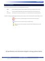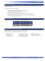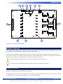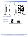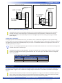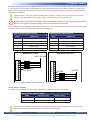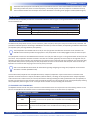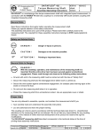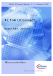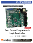
1
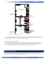
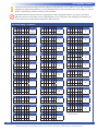
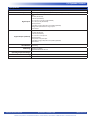
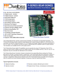
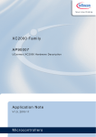
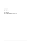
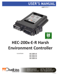
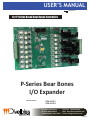
USER’S MANUAL
Revision: 1
For P-Series Based Bear Bones Controllers
P-Series Bear Bones
I/O Expander
Covered Models:
ICM-IO-C21
ICM-IO-C24
Divelbiss Corporation
9778 Mt. Gilead Road,
Fredericktown, Ohio 43019
Toll Free: 1-800-245-2327
Web: http://www.divelbiss.com
Email: [email protected]
2013009.1
Table of Contents
Manual Contents
Getting Started
How to Use this Manual........................................................................ 3
The ICM-IO-CXX Overview..................................................................... 4
The ICM-IO-CXX Models........................................................................ 4
Getting to Know the ICM-IO-CXX I/O Expander..................................... 4
ICM-BB-IO-CXX Mounting...................................................................... 5
Configuration Jumpers........................................................................... 5
I/O Expander Features
Input Power........................................................................................... 8
Digital Inputs......................................................................................... 8
Digital Outputs....................................................................................... 9
LED Indicators...................................................................................... 11
I/O-A & I/O-B Ports.............................................................................. 11
I/O Expander Address Selector............................................................ 12
Using the Digital Inputs and Digital Outputs....................................... 14
Specifications....................................................................................... 15
ICM-IO-CXX User’s Manual
Document #: 2013009.1.pdf
Divelbiss Corporation • 9778 Mt. Gilead Road • Fredericktown, Ohio 43019 • 1-800-245-2327 • www.divelbiss.com
PAGE 1 of 15
Getting Started
This section explains how to read this manual and understand the symbols and information that it contains and basic ICM-IO-CXX
product information.
WARNING!!
The ICM-IO-CXX P-Series Bear Bones I/O Expander must not be used in applications which
could be hazardous to personnel in the event of failure of this device. Precautions must be
taken by the user to provide mechanical and/or electrical safeguards external to this device.
This device is NOT APPROVED for domestic or human medical use.
Getting Started
How to Use this Manual
In this manual, the following conventions are used to distinguish elements of text:
BOLD
italic
SMALL CAPS
Denotes labeling, commands, and literal portions of syntax that must appear exactly as shown.
Used for variables and placeholders that represent the type of text to be entered by the user.
Used to show key sequences or actual buttons, such as OK, where the user clicks the OK button.
In addition, the following symbols appear periodically in the left margin to call the readers attention to specific details in the text:
Warns the reader of a potential danger or hazard associated with certain actions.
Appears when the text contains a tip that is especially useful.
Indicates the text contains information to which the reader should pay particularly close
attention.
All Specifications and Information Subject to Change without Notice
ICM-IO-CXX User’s Manual
Document #: 2013009.1.pdf
Divelbiss Corporation • 9778 Mt. Gilead Road • Fredericktown, Ohio 43019 • 1-800-245-2327 • www.divelbiss.com
PAGE 3 of 15
Getting Started
The ICM-IO-CXX Overview
The ICM-IO-CXX I/O Expander provides add-on I/O to the P-Series Bear Bones Controllers (ICM-BB-P13-XX) in groups of 8 digital
inputs and 8 digital outputs.
The ICM-IO-CXX boasts the following capabilities:
•
•
•
•
•
•
•
8 to 32VDC Operation / 90-130VAC Operation (Model Dependent)
-40°C to 80°C Operating Temperature Range
8 Digital Inputs, Sinking or Sourcing (in groups of 4) with LED indicators
Digital Inputs debounce is configurable using jumpers.
8 Digital Outputs, rated 2 Amps each, either 8-32VDC or 90-130VAC (Model dependent)
One CAN Port, 2 I/O Connectors for connecting to controllers and addtional I/O Expanders
Power Monitor LED and Status/Watchdog LED
The ICM-IO-CXX Models
The following I/O Expander models are available for the P13 Series Bear Bones Controller.
I/O Power
#
Inputs
#
Outputs
Expandable
I/O
ICM-IO-C21
8-32VDC
8
8
Yes
ICM-IO-C24
90-130VAC
8
8
Yes
Model
Getting to Know the ICM-IO-CXX I/O Expander
The ICM-IO-CXX I/O Expander is designed to expand the I/O capabilities of the P-Series Bear Bones controllers (ICM-BB-P13-XX);
however, the ICM-IO-CXX is compatible with any OptiCAN enabled controller.
Figure 1-1 illustrates the ICM-IO-CXX I/O Expander and it’s standard features.
1. Watchdog LED Indicator
2. Power Status LED
3. I/O-A CAN Connector
4. I/O-B CAN Connector
ICM-IO-CXX User’s Manual
5. CAN Termination Jumper
6. I/O Address Selector (Node ID)
7. Digital Output Terminal Blocks
8. Digital Output LED Indicators
9. Digital Input LED Indictors
10. Digital Input Debounce Jumpers
11. Digital Input Terminal Blocks
Document #: 2013009.1.pdf
Divelbiss Corporation • 9778 Mt. Gilead Road • Fredericktown, Ohio 43019 • 1-800-245-2327 • www.divelbiss.com
PAGE 4 of 15
Getting Started
PWR
INPUTS
4
5
6
DB6
DB7
DB8
I/O-B
OUTPUTS
DIGITAL
I/O-A
DI1
5
DI2
DI3
DO2
DO3
DO4
DO5
DO6
10
7 6 5 4 C C 3 2 1 0
DB5
4
DO1
DI4
DB4
3
DO0
DI5
0 1 2 3 C C 4 5 6 7
DB3
I/O
TERMINATOR
2
1 2 3 4 5
DI6
DB2
JMP1
7
DO7
DI7
DIGITAL
INPUTS
DB1
DI0
1
11
I/O
ADDRESS
ON
OUTPUTS
W/D
3
+VA
LO
HI
2
+VA
LO
HI
1
9
8
Figure 1-1 - ICM-IO-CXX I/O Expander
ICM-BB-IO-CXX Mounting
The ICM-BB-IO-CXX I/O Expanders are designed as subplate mount and are mounted using hardware including spacers, screws and
nuts as needed (not included). Figure 1-2 illustrates the mounting dimensions.
The ICM-IO-CXX I/O Expanders typically mount to the lower side of the controller where the I/O Port (CAN Port) is located. This
aligns the I/O connectors on the controllers and expanders. The cables provided with the expanders are long enough to connect the
expander to the controller (or other expanders) as long as this mounting location is used.
Mounting expanders at different locations may require additional cabling (not provided).
For noise immunity, the mounting hardware should be connected electrically to earth ground.
Configuration Jumpers
The ICM-IO-CXX I/O Expander have configurable jumpers setting optional features. Refer to Figure 1-1 for jumper locations. The
jumpers have 3 positions and removable shunts are provided.
To configure a jumper, remove and then re-install the shunt on the pins (typically numbered 1-3). Refer to Figure 1-3 for a sample of
a jumper and shunt. Jumper pin 1 is designated with a ‘1’ silkscreened on the PCB.
ICM-IO-CXX User’s Manual
Document #: 2013009.1.pdf
Divelbiss Corporation • 9778 Mt. Gilead Road • Fredericktown, Ohio 43019 • 1-800-245-2327 • www.divelbiss.com
PAGE 5 of 15
Getting Started
4.25
W/D
4.25
PWR
OUTPUTS
DO0
DI1
DIGITAL
INPUTS
DIGITAL
OUTPUTS
DI0
INPUTS
7 6 5 4 C C 3 2 1 0
DI4
DI5
DO3
DO5
DI6
DI3
DO2
DO4
DO6
DI7
0 1 2 3 C C 4 5 6 7
4.90
DI2
DO1
4.90
DO7
4.25
4.25
Figure 1-2 - I/O Expander Mounting
Jumper Example: Pull
Jumper as shown and
install from Pins 1 to 2
or Pins 2 to 3 based on
setting required.
Figure 1-3 - Jumper / Shunt Example
ICM-IO-CXX User’s Manual
Document #: 2013009.1.pdf
Divelbiss Corporation • 9778 Mt. Gilead Road • Fredericktown, Ohio 43019 • 1-800-245-2327 • www.divelbiss.com
PAGE 6 of 15
I/O Expander Features
This sections explains the I/O Expander features and functions and provides hints and important information for configuring and using the ICM-IO-CXX I/O Expanders.
I/O Expander Features
Input Power
The ICM-IO-CXX I/O Expander is powered from the P-Series Bear Bones Controller (ICM-BB-P13-XX) via the I/O-A or I/O-B port and
cable (the one connected to the controller). The I/O Expander will operate over a wide voltage range.
Input Power
From Controller
8-32 VDC
Typical Current (Excludes I/O)
Typical 13mADC @ 24VDC (Controller Input Power)
I/O-A , IO-B Pin-Out
PIN ID
CONNECTION
HI
CAN HI connection
LO
CAN LO connection
+VA
+VA, Input Power from Controller (8-32 VDC)
Digital Ground
The I/O Expanders are available with AC or DC I/O. The I/O type does not affect the connections to the controller. The
ICM-BB-P13-XX controller provides the logic power to the I/O expander via the cable plugged into the I/O connector port
When connected to a DC Model Controller, the typical input power to the expander will be the input voltage of the controller. When connected to an AC Model Controller, the typical input power will about 15VDC. This 15VDC is unregulated and can change based on the loading (number of I/O expanders used).
Digital Inputs
The ICM-IO-CXX I/O Expanders support eight on-board digital inputs. These eight digital inputs are divided into two groups of four
inputs (Inputs 0-3 and Inputs 4-7). Refer to Figure 1-1 for the location of the digital input terminal block. An LED indictor is provided
for each digital input. Each digital input also has optional debounce that may be enabled or disabled via jumpers. See later this section for debounce information.
Each digital input group contains four digital input terminals (0, 1, 2,3 or 4,5,6,7) and one digital input common for each group (C).
This discrete common provides the functionality of wiring input devices to the terminal blocks as sinking or sourcing. All the digital
inputs in a group must be used the same as all sinking or all sourcing), but each group may be used as sinking or sourcing independently of the other.
All digital inputs in one group must ALL be utilized as the same type: sinking or sourcing. Each group may be used as
sinking or sourcing provided that all the digital inputs in the group are used and wired the same.
Figure 2-1 illustrates connecting digital inputs (digital inputs 0-3) as sinking inputs (with a sourcing device) and connecting digital
inputs (digital inputs 4-7) as sourcing inputs (with a sinking device).
DIGITAL INPUT GROUP A Pin-Out
DIGITAL INPUT GROUP B Pin-Out
PIN ID
CONNECTION
PIN ID
CONNECTION
0
Digital Input 0
C
Group Digital Input Common
1
Digital Input 1
4
Digital Input 4
2
Digital Input 2
5
Digital Input 5
3
Digital Input 3
6
Digital Input 6
C
Group Digital Input Common
7
Digital Input 7
ICM-IO-CXX User’s Manual
Document #: 2013009.1.pdf
Divelbiss Corporation • 9778 Mt. Gilead Road • Fredericktown, Ohio 43019 • 1-800-245-2327 • www.divelbiss.com
PAGE 8 of 15
I/O Expander Features
SOURCING INPUTS
SINKING INPUTS
SOURCING INPUT
DEVICES
SINKING INPUT
DEVICES
+VDC / AC LINE
0
0
DC COMMON
/ AC NEUT
1
DC COMMON
/ AC NEUT
2
3
C
C
1
2
3
C
C
4
4
5
6
7
+DC / AC LINE
5
6
7
Figure 2-1 - Digital Inputs Sinking / Sourcing
The digital inputs status are automatically broadcast to the connected ICM-BB-P13-XX controller (or other controller)
provided the I/O bus is connected properly, terminated properly and the I/O Expander is addressed correctly. The
connected controller has the responsibility to ‘listen’ for the digital inputs and act according to the program installed
(ladder diagram).
DIGITAL INPUT DEBOUNCE
Each digital input has on-board debounce circuitry. The debounce circuit is individually configurable on a per input basis using
jumpers and shunts. They are identifyed on the ICM-IO-CXX as DB1 - DB8 for digital inputs 0-7 respectively. To enable the debounce
on a digital input, set the shunt of the DBx jumper from pin 1 to pin 2. To disable the debournce on a digital input, set the shut of
the DBx jumper from pin 2 to pin 3.
Note: Pin 1 for each digital input DBx jumper is closest to the middle of the controller. Pin 3 is the closes to the edge of the controller board. Pin 2 is the center pin.
`
The digital inputs voltage is model dependent. The inputs will operate over the range shown, with the minimum voltage shown as the voltage where the input is guaranteed to be “ON”. The inputs may be “ON” below the shown voltage but there is no guarantee.
DIGITAL INPUT VOLTAGE RANGE
Model
Minimum Voltage for “ON”
Maximum Voltage
ICM-IO-C24
8 VDC
32 VDC
ICM-IO-C21
90 VAC
130 VAC
Digital Outputs
The ICM-IO-CXX I/O Expanders support eight on-board digital outputs. These eight digital outputs are divided into two groups of
four outputs Refer to Figure 1-1 for the location of the digital output terminal block. An LED indictor is provided for each digital
output.
The ICM-IO-CXX I/O Expander provides on-board noise suppression. It is highly recommended to add off-board protection devices: diodes across output loads for DC models and Metal Oxide Varistors (MOVs) across output loads for AC models. Ideally, these devices should be physically located at or as close to the load device as possible.
ICM-IO-CXX User’s Manual
Document #: 2013009.1.pdf
Divelbiss Corporation • 9778 Mt. Gilead Road • Fredericktown, Ohio 43019 • 1-800-245-2327 • www.divelbiss.com
PAGE 9 of 15
I/O Expander Features
Each digital output group contains four digital output terminals (0, 1, 2,3 or 4,5,6,7) and one digital output common for each group
(C). This discrete common provides the functionality of wiring output devices to the terminal block as sinking or sourcing. All the
digital outputs in a group must be used the same as all sinking or all sourcing), but each group may be used as sinking or sourcing
independently of the other.
All digital outputs in one group must ALL be utilized as the same type: sinking or sourcing. Each group may be used as
sinking or sourcing provided that all the digital outputs in the group are used and wired the same.
AC Model outputs may be wired as Sinking or Sourcing while DC Model outputs only support Sinking. Wiring DC Model
outputs as sourcing will result with loads being active and may damage the I/O Expander.
Figure 2-2 illustrates connecting digital outputs (digital outputs 0-3) as sinking outputs (with a sourcing device) and connecting digital outputs (digital outputs 4-7) as sourcing outputs (with a sinking device).
DIGITAL OUTPUT GROUP A Pin-Out
DIGITAL OUTPUT GROUP B Pin-Out
PIN ID
CONNECTION
PIN ID
CONNECTION
0
Digital Output 0
C
Group Digital Output Common
1
Digital Output 1
4
Digital Output 4
2
Digital Output 2
5
Digital Output 5
3
Digital Output 3
6
Digital Output 6
C
Group Digital Output Common
7
Digital Output 7
SINKING OUTPUTS
SOURCING OUTPUTS
+VDC / AC LINE
0
LOAD
1
LOAD
2
3
C
C
LOAD
LOAD
0
1
DC COMMON
/ AC NEUT
4
5
6
7
2
3
C
C
AC LINE
4
LOAD
5
6
7
LOAD
LOAD
AC NEUT
LOAD
Figure 2-2 - Digital Outputs Sinking / Sourcing
DIGITAL OUTPUT RATINGS
Each digital output will operate over the voltage range shown and supports a load up to 2 Amps each.
DIGITAL OUTPUT VOLTAGE RANGE
Model
Minimum Voltage
Maximum Voltage
ICM-IO-C24
8 VDC
32 VDC
ICM-IO-C21
90 VAC
130 VAC
The digital outputs voltage is model dependent. The outputs will operate over the range shown. The outputs may be
operate below the minumim voltage shown, but operation is not guaranteed.
ICM-IO-CXX User’s Manual
Document #: 2013009.1.pdf
Divelbiss Corporation • 9778 Mt. Gilead Road • Fredericktown, Ohio 43019 • 1-800-245-2327 • www.divelbiss.com
PAGE 10 of 15
I/O Expander Features
The ICM-IO-CXX I/O Expander automatically listens for broadcasts from the connected ICM-BB-P13-XX controller (or other
controller) provided the I/O bus is connected properly, terminated properly and the I/O Expander is addressed correctly.
The connected controller sets the output control status broadcasts it according to the program installed (ladder diagram).
LED Indicators
The ICM-IO-CXX I/O Expander provides two on-board LED indicators. Refer to Figure 1-1 for general locations of the LED indicators.
The two indicators are:
LED INDICATORS
LED NAME
POWER
WATCHDOG
DESCRIPTION
Power OK (green). On when proper input power is detected.
Watchdog (red). Flashes when the I/O Expander is operating correctly.
I/O-A & I/O-B Ports
The ICM-IO-CXX I/O Expander has two I/O Port connectors (I/O-A and I/O-B). These ports two ports are electrically connected. This
provides two identical ports for connecting to ICM-BB-P13 controllers (or other controllers) and expanding to additional ICM-IO-CXX
I/O Expanders (daisy chaining additiona I/O Expanders).
The I/O Expanders are available with AC or DC I/O. The I/O type does not affect the connections to the controller. The
ICM-BB-P13-XX controller provides the logic power to the I/O expander via the cable plugged into the I/O connector port.
The I/O Expander connects to the ICM-BB-P13-XX controller via its I/O port. Refer to Figure 1-1 for general location of the I/O-A and
I/O-B Ports. The I/O expander should be mounted in-line with the controller (physically the same width) on the edge with the I/O
expander connector of the controller. This will align the I/O connectors of the controller and the I/O expander near each other. Plug
the provided cable (with the I/O Expander) into the I/O expander connector of the controller and the I/O-B connector of the I/O
Expander. The connectors will only plug-in the correctly as they are keyed.
Refer to the ICM-BB-P13-XX Controller for information regarding configuring and using the I/O expander on the P-Series Bear Bones controller (ICM-BB-P13-XX).
As the ICM-IO-CXX I/O Expander uses the OptiCAN network, multiple I/O expanders may be connected to one controller. Each
expander connected must have a uniquie I/O Address (network address). The design of the expanders allows multiple expanders
to be mounted in-line and thus their I/O-A and I/O-B connectors will align allowing the cable (provided with each I/O expander) to
be used to connect first from the controller to the first expander and then from each expander to the next expander (daisy chaining
the I/O expanders). Refer to Figure 2-3 for an example of the controller and I/O mounting and connections.
I/O EXPANDER PORT TERMINATION
The OptiCAN network used for the I/O bus is based on a CAN network and as such requires the use of terminating resistors on the
I/O bus. The ICM-BB-P13-XX controllers have an on-board terminating resistor as do each of the I/O expanders.
I/O BUS TERMINATOR JUMPERS
Jumper ID
Description
JMP7
ICM-BB-P13-XX Controller I/O Bus Termination Jumper. Pins 1-2 Disables the
terminating resistor from the I/O Bus. Pins 2-3 Enables the terminating resistor on
the I/O Bus.
JMP1 or
I/O TERMINATOR
ICM-IO-CXX User’s Manual
ICM-IO-CXX Expander I/O Bus Termination Jumper. Pins 1-2 Disables the terminating resistor from the I/O Bus. Pins 2-3 Enables the terminating resistor on the I/O
Bus.
Document #: 2013009.1.pdf
Divelbiss Corporation • 9778 Mt. Gilead Road • Fredericktown, Ohio 43019 • 1-800-245-2327 • www.divelbiss.com
PAGE 11 of 15
I/O Expander Features
ULED1
ULED2
POWER
0
1
2
3
4
5
6
7
P1 P2
POWER
IN
ANALOG
I/O
C 3 2 1 0
0 1 2 3 C
ICM-BB-P13-XX
C 4 5 6 7
7 6 5 4 C
DIGITAL
OUTPUTS
DIGITAL
INPUTS
I/O
INPUTS
CABLE FROM I/O
CONTROLLER
TO I/O-B EXPANDER
OUTPUTS
I/O-A
0 1 2 3 C C 4 5 6 7
7 6 5 4 C C 3 2 1 0
DIGITAL
INPUTS
DIGITAL
OUTPUTS
I/O-B
ICM-IO-CXX
CABLE FROM I/O-A
EXPANDER
TO I/O-A EXPANDER
OUTPUTS
I/O-A
I/O-B
DIGITAL
INPUTS
0 1 2 3 C C 4 5 6 7
ICM-IO-CXX
ENABLE TERMINATOR ON
LAST EXPANDER
DIGITAL
OUTPUTS
INPUTS
7 6 5 4 C C 3 2 1 0
ENABLE TERMINATOR ON
CONTROLLER
CONTINUE CABLE
CONNECTION IN PATTERN
AS SHOWN I/O-B TO
I/O-B, I/O-A TO IO-A FOR
ADDITIONAL
EXPANDERS
Figure 2-3- I/O Expansion Cabling
Only the ENDS of the I/O Bus (first and last devices) are to have the terminators (terminating resistors) enabled. Failure to
enable the terminators, the correct terminators or enabling an incorrect number of terminators may result in I/O bus
communication errors or loss of communication at all. Refer to Figure 2-3.
USING OPTICAN DEVICES ON THE I/O PORT
The I/O Port utilizes the OptiCAN network for all communications. As such, any product that supports the Divelbiss
OptiCAN network may be connected to the I/O port. All OptiCAN communication is network based. Refer to the P-Series EZ LADDER Toolkit manual for details and information regarding the OptiCAN network and registers. Refer to the
connected product manual for information regarding the connections needed and terminations.
I/O Expander Address Selector
The ICM-IO-CXX I/O Expander using the OptiCAN network for communcating to controllers and as such each I/O Expander is
required to have a unique address on the I/O Bus (OptiCAN network). The address for each I/O board is set by its on-board I/O Address Selector. Refer to Figure 1-1 for the location of the address selector.
ICM-IO-CXX User’s Manual
Document #: 2013009.1.pdf
Divelbiss Corporation • 9778 Mt. Gilead Road • Fredericktown, Ohio 43019 • 1-800-245-2327 • www.divelbiss.com
PAGE 12 of 15
I/O Expander Features
The ICM-IO-CXX I/O Expander supports network addresses (I/O Addresses) of 1-31. Address 0 is not valid. The address is configured by setting the dip switches 1-5 on the I/O Address Selector. Each switch represents a binary digit 1, 2, 4, 8 and 16 for 1-5 respectively. The binary number sets the I/O Address.
The Address Selector should be set prior to applying power. When changing the address, cycle power reset the I/O
Addresses. Failure to set the address prior to applying power or not cycling power after changing the I/O Address may result in failure for the ICM-IO-CXX I/O Expander to operate correctly.
Dip Switch Setting - I/O Address
1
2
3
4
5
I/O Address
SW
1
2
X
X
X
X
X
X
X
255
Illigeal
ON
OFF
OFF
SW
1
2
3
4
5
I/O Address
SW
ON
X
X
X
X
X
2
3
4
5
SW
ON
OFF
SW
1
ON
X
OFF
X
SW
1
2
ON
X
X
OFF
SW
1
2
ON
X
X
X
3
4
5
X
X
X
3
4
5
X
OFF
X
X
SW
1
2
ON
X
OFF
SW
3
ON
2
3
X
X
OFF
X
SW
1
2
3
ON
X
X
X
OFF
SW
1
X
4
5
X
X
1
X
2
3
ON
X
X
4
5
X
X
4
5
X
X
4
5
X
OFF
X
X
X
SW
1
2
3
ON
X
OFF
SW
1
ON
X
4
5
X
X
X
2
3
X
OFF
X
X
4
5
X
X
ICM-IO-CXX User’s Manual
X
1
I/O Address
2
I/O Address
3
I/O Address
4
I/O Address
5
I/O Address
6
I/O Address
7
I/O Address
8
I/O Address
9
I/O Address
10
4
2
OFF
X
X
SW
1
2
ON
X
ON
OFF
X
3
4
X
X
ON
3
4
X
X
2
3
4
X
X
X
X
SW
1
2
3
4
ON
X
X
X
X
1
2
3
4
5
X
OFF
X
X
X
X
SW
1
2
3
4
ON
X
OFF
1
ON
X
X
X
2
3
4
X
X
SW
1
2
ON
X
X
OFF
1
5
X
OFF
2
ON
X
X
SW
1
2
ON
X
X
X
3
4
5
X
X
X
3
4
5
X
X
3
4
X
X
5
X
X
OFF
OFF
5
X
ON
SW
5
X
OFF
SW
5
X
OFF
SW
5
X
X
1
5
X
X
1
SW
3
5
X
X
I/O Address
11
I/O Address
12
I/O Address
SW
1
ON
2
3
X
X
OFF
X
SW
1
2
3
ON
X
X
X
1
2
3
4
5
X
X
4
5
X
X
4
5
X
X
3
4
5
X
X
X
3
4
5
X
X
X
2
3
4
5
X
X
X
X
X
I/O Address
SW
1
2
3
ON
X
1
ON
X
X
2
3
X
15
OFF
X
I/O Address
SW
1
2
16
ON
X
X
OFF
I/O Address
SW
1
2
OFF
X
X
I/O Address
SW
1
2
ON
X
SW
3
I/O Address
24
I/O Address
25
I/O Address
26
I/O Address
27
I/O Address
28
I/O Address
29
X
1
ON
19
OFF
X
I/O Address
SW
1
2
3
4
5
20
ON
X
X
X
X
X
OFF
I/O Address
23
X
ON
I/O Address
I/O Address
X
17
OFF
22
X
X
X
18
5
X
X
SW
4
5
OFF
I/O Address
X
4
ON
OFF
I/O Address
X
13
14
5
X
OFF
SW
4
I/O Address
30
I/O Address
31
X = SWITCH SETTING
21
Document #: 2013009.1.pdf
Divelbiss Corporation • 9778 Mt. Gilead Road • Fredericktown, Ohio 43019 • 1-800-245-2327 • www.divelbiss.com
PAGE 13 of 15
I/O Expander Features
Using the Digital Inputs and Digital Outputs
The I/O Expanders use the OptiCAN network. OptiCAN is a register based communcation protocol which supports muliple nodes
(devices). Digital Inputs are automatically read the input bits are packed into a register as an integer. The I/O Expander automatically listens for broadcasts from the controller (connected to the I/O bus). It automatically unpacks the integer in the output register
and updates the digital output status accordingly.
For the I/O to operate, the ICM-IO-CXX must be connected to a controller using the I/O bus network (I/O-A or I/O-B) connector, the
network must be properly wired and terminated (terminating resistors enabled). The digital inputs and digital outputs are accessed
via packed integers in OptiCAN registers and as the controller’s ladder diagram executes will read and update (provided they are
programmed in the ladder diagram).
There is no software configuration or programming on the ICM-IO-CXX I/O Expander. All functionality is controlled via the connected controller (network communication, digital input unpacking, digital input packing). Refer to the ICM-BB-P13-XX User manual for details on implementing and using the ICM-IO-CXX I/O Expander with the controller and accessing the I/O in the ladder diagram.
I/O EXPANDER REGISTER ASSIGNMENTS
Each I/O Expander uses the same register numbers for digital inputs and digital outputs. Three additional registers are used to broadcast node status and communication errors. These registers are common to all I/O Expanders and are only
differentiated by the controller based on the address ID (node ) set on each I/O Expander. The registers shown are for reference only as they are not configurable at the I/O Expander.
I/O Expander Register Assignments
Register
Description
0
All digital inputs status - Packed as an integer.
1
All digital outputs control - Packed as an integer.
189
CAN Receive Error Count - read only
190
CAN Transmit Error Count - read only
191
Node Status - Status of Node on network
An example program for the ICM-BB-P13-XX controller and I/O Expander is availabe from our website
(www.divelbiss.com). Browse to the ICM-BB-P13-XX product page and select the ‘Documents / Downloads’ tab in the page. Located in the ‘Software’ section will be sample program (P13IOExpander.zip) for using the I/O Expander on the OptiCAN network. Download and unzip this file to have access to the ladder diagram file.
STARTING THE OPTICAN / I/O EXPANDER NETWORK
Before any network communication can occur, the I/O network must be started. The network can only be started by the broadcast
of a START NETWORK command from a connected controller. Refer to the ICM-BB-P13-XX controller manual for details on implementing and starting the I/O network.
ICM-IO-CXX User’s Manual
Document #: 2013009.1.pdf
Divelbiss Corporation • 9778 Mt. Gilead Road • Fredericktown, Ohio 43019 • 1-800-245-2327 • www.divelbiss.com
PAGE 14 of 15
I/O Expander Features
Specifications
Controller P-Series Bear Bones Controller or any OptiCAN enabled Controller
Input Power 8-32 VDC, typical 13mA @ 24VDC Input Power (no loads) (DC Models)
Qty 8
8-32 VDC (DC Models)
9-130 VAC (AC Models)
Sink or Source in Groups of 4 (AC Models)
Digital Inputs Sink in Groups of 4 (DC Models)
Optically Isolated
Expandable using I/O Expanders and I/O Bus (OptiCAN).
Configurable Input Debounce using Jumpers
LED Indicators
Qty 8
8-32 VDC (DC Models)
9-130 VAC (AC Models)
Sink or Source in Groups of 4.
Digital Outputs (onboard)
Optically Isolated
2 Amps Maximum per Output
Expandable using I/O Expanders and I/O Bus (OptiCAN).
LED Indicators
LED Indicators
Addressing
1 Power
1 Watchdog
5 Position Dip Switch
OptiCAN Node Address of 1-31.
Operating Temperature Range -40˚C to 80˚C
Mounting Open-Board, Stand-off Mounted
Size 9” x 5.4” x 1.5”
ICM-IO-CXX User’s Manual
Document #: 2013009.1.pdf
Divelbiss Corporation • 9778 Mt. Gilead Road • Fredericktown, Ohio 43019 • 1-800-245-2327 • www.divelbiss.com
PAGE 15 of 15