1
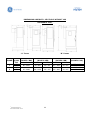
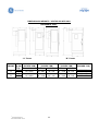
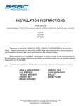
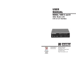
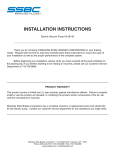
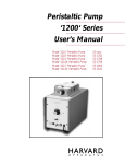
®
Vector VII
Product Data Book
GE Oil & Gas
5500 S.E. 59th Street
Oklahoma City, OK 73135
Tel 405-670-1431
www.geoilandgas.com/artificiallift
SAFETY NOTICE
GE Oil & Gas places a high priority upon personnel safety. Personnel performing
maintenance upon drives should be properly trained and follow all safety procedures to
prevent injury. Drives may cause serious injury if proper safety precautions, equipment, and
installation procedures are not used. Units should always be grounded and confirmation of
ground connection and continuity be established prior to performing any work or service. Be
sure to consult user’s manual before installing, energizing, or operating equipment. Installation
should always conform to local codes, regulations, or other authorities governing electrical
equipment.
©
GE Oil & Gas 2012
Revised November 2010
2
TABLE OF CONTENTS
TOPIC
©
PAGE NUMBER
Safety Notice
2
Introduction
5
Drive Description
5
Vector® VII Product Summary
6
Installation Examples
8
Catalog Number Explanation
9
Vector® VII without VSG® Catalog Numbers – 480 VAC 60 Hertz
10
Vector® VII with VSG® Catalog Numbers – 480 VAC 60 Hertz
11
Vector® VII without VSG® Catalog Numbers – 400 VAC 50 Hertz
12
Vector® VII with VSG® Catalog Numbers – 400 VAC 50 Hertz
13
Vector® VII Factory Installed Options
14
Manufacturer Qualifications and Certifications
17
General Specifications / Operating Conditions / Design Features
17
Operator Panel
22
Surface Pumping Systems (SPS™)
33
Input Harmonic Mitigation
34
Basic 12 Pulse and 18 Pulse Drive Schematics
35
Multi-Pulse Drives and Phase Shift Transformer Operation
36
Output Harmonic Mitigation
38
Grounding and Bonding / Typical 480 VAC Drive Installation
39
Generator Requirements
40
Custom Packages
42
Dimensions and Weights
44
Terms and Definitions
48
GE Oil & Gas 2012
Revised November 2010
3
©
GE Oil & Gas 2012
Revised November 2010
4
INTRODUCTION
This document provides a descriptive overview of the Vector® VII Variable Speed Drive (VSD)
available from GE Oil & Gas. Information is provided on available ratings, physical size, product
features, general operation, and available options. Additional details regarding drive set-up,
operation, and troubleshooting are available in the Vector VII Variable Speed Drive User’s
Manual. The descriptions and information contained in this publication are for informational
purposes only and should not be used to install, set-up, program, or operate the Vector VII drive.
Note: This publication describes the standard Vector VII Variable Speed Drive and includes
descriptions of the most common drive options and modifications. Specific features may be
added (or disabled) from the product depending on the specific application. All specifications
and information contained in this publication are subject to change without notice.
DRIVE DESCRIPTION
The Vector VII Variable Speed Drive is designed specifically for oil-field pumping applications
including electrical submersible pumps (ESP) and surface pumping systems (SPS). Vector VII
drives are available in ratings from 104 KVA to1500 KVA. They are provided in rugged outdoor
rated enclosures designed for a wide variety of environments ranging from arctic to desert
conditions. Application specific software and a GE Oil & Gas Custom Operator Control Panel
combine to optimize pump control while simplifying drive operation.
Vector VII uses the latest Insulated Gate Bipolar Transistor (IGBT) technology in combination
with surface mount printed circuit boards to create a VSD of the highest reliability, and small
physical size. Fixed voltage, three-phase AC input power is first converted to a fixed DC bus
voltage by the input rectifier section of the drive. That fixed DC bus voltage is then processed
by the inverter section to produce a sine coded variable voltage, variable frequency output to
control the speed of the motor.
For ESP applications, the Vector VII Variable Speed Drive is available with integrated VSG®
Technology. With VSG Technology the drive output voltage waveform is a near perfect sinewave which results in improved motor performance, extended motor run life, extended motor
cable life, and increased operational efficiency in the driven equipment. Vector VII drives with
VSG (Variable Sinewave Generation) technology can successfully operate with motor cable
lengths up to 15,000 ft.
User adjustments include operating speed, acceleration and deceleration rates, motor overload
protection settings, auto restarts, time delays, and stopping methods. Control methods include
frequency control, current control, pressure control, or analog follower (Analog 1 = 0-10 VDC,
Analog 2 = 0-10 VDC or 4-20 mA) capability.
©
GE Oil & Gas 2012
Revised November 2010
5
VECTOR VII PRODUCT SUMMARY
Standard Drive Features:
•
•
•
•
•
•
•
•
•
•
•
•
•
•
•
•
•
•
Ratings from 104 KVA to 1500 KVA.
Specifically designed for oil field pumping applications.
NEMA 3R outdoor enclosure, rugged (10 Gauge) steel construction with compact footprint.
Enclosure base pre-drilled with slotted holes for permanent attachment to foundation.
Three point door latching mechanism.
Designed for 50ºC (122º F) ambient temperature, white enclosure reduces solar heating.
Input AC line circuit breaker with pad lockable flange mount external operator.
State of the art operator control panel with graphical interface.
Available with or without Variable Sinewave Generator (VSG) technology – pure sine wave output.
Latest generation IGBTs (Insulated Gate Bipolar Transistors).
Microprocessor based control circuitry with non-volatile memory for all drive parameters.
Surface mount technology with protective coating on all printed circuit boards.
Input line transient voltage suppression - line to line and line to ground voltage surge protection.
Six pulse input rectification (standard) or optional multi-pulse rectification for reduced AC line harmonics.
Fused control power transformer.
Extended acceleration time - reduces electrical and mechanical stress on pump and motor.
“S” curve soft start / soft stop capability.
Power loss ride through capability.
Operator Panel Features:
•
•
•
•
•
•
•
•
•
•
•
•
•
•
•
•
•
•
•
©
Intuitive operator friendly menu is easy to use.
Large bright screen is easy to read in direct sunlight.
Built in real time clock – provides time and date stamp for historical data and event logger.
Operator control panel monitors both drive parameters and well parameters.
Note: GE Oil & Gas downhole sensor is required to monitor well parameters.
Drive and well parameters are displayed in engineering units using plain language text.
User programmable functions and operating modes.
Set point PI control – closed loop – programmable in engineering units.
Comprehensive run status screen shows critical drive and well data in a single location.
Time stamped event and fault log - stores last 256 drive events including faults, starts, stops, operator
changes, etc.
Historical data log - periodically samples and stores the values of 20 different drive and well parameters.
- All parameters are time (to the second) and date stamped with 35 days of data retained.
Trending screen – graphically displays historical data for important drive and well parameters.
Software embedded circular recording ammeter – high resolution display with 1 day or 7 day format.
Drive Status Lights
- Shows drive operating mode and are visible from a distance.
Software embedded drive lock-out and auto-restart switches.
Programmable restart capability.
USB port for data retrieval and transfer of drive information to memory stick.
- Save historical data, event log information, recording ammeter data, and drive configuration
information.
Built in Modbus communications port – easy interface to customer SCADA systems.
Multiple Languages
Password protection to prevent unauthorized changes.
GE Oil & Gas 2012
Revised November 2010
6
Protective Features:
•
•
•
•
•
•
•
•
•
•
•
•
•
•
•
Input phase insensitive – sequencing of 3 phase input power is not necessary.
DC bus reactor.
Diagnostic fault indication.
Loss of load detection.
Serial communication loss detection.
Short circuit protection.
Ground fault protection.
Loss of input phase protection.
Over voltage and under voltage protection.
Over current and under current protection.
Current limiting DC bus fuse.
Motor stall protection.
Heat sink over temperature protection.
Adjustable motor current limit.
Critical frequency avoidance – three selectable frequencies with adjustable bandwidth.
Electrical Specifications:
Rated Input Voltage:
Efficiency:
Power Factor:
Output Voltage:
Output Frequency:
480 Volt, 3 phase, 60 Hz (+ / - 10% of rated voltage and frequency).
Consult factory for other input voltages and frequency ratings.
97% or greater at full load.
.95 or greater – Constant over operating range – Not speed or load dependent
0 Volts to rated input voltage
0 Hertz to 120 Hertz.
Control Specifications:
Control Method:
Accel / Decel:
Drive Overload:
Current Limit:
Sine coded output with optional VSG (Variable Sinewave Generation)
technology.
0 Seconds to 6,000 seconds.
110% of drive rating for 60 seconds (Variable Torque).
Programmable current limit.
Control I/O:
Digital Inputs:
Digital Outputs:
Analog Inputs:
Analog Outputs:
Analog Reference:
Logic Reference:
7 Programmable inputs - 24 VDC, 8 mA – Sinking or Sourcing Logic.
2 Programmable dry contacts rated 250 VAC / 30 VDC @ 1A.
1 Fault contact - Form C dry contact rated 250 VAC / 30 VDC @ 1A.
2 Programmable inputs (10 bit).
Analog 1 = 0 to +10 VDC – 20 K Ohms
Analog 2 = 0 to +10 VDC – 20 K Ohms or 4 to 20 mA – 250 Ohms
2 Programmable outputs (10 bit) each = 0 to +10 VDC – 2 mA.
+15 VDC Source – 20 mA.
+24 VDC Source – 8 mA.
Environmental Specifications:
Ambient Service Temperature:
Ambient Storage Temperature:
Humidity:
Altitude:
Vibration:
©
GE Oil & Gas 2012
Revised November 2010
0°C to 50°C (32°F to 122°F) to -40°C (-40°F) with optional arctic package.
-20°C to 60°C (-4°F to 140°F)
0 to 100%
Up to 1000 Meters (3300 Feet) without de-rate.
9.81m/s2 (1 G) maximum at 10 to 20 Hz, 2.0 m/s2 (0.2 G) at 20 Hz to 50 Hz.
7
Various Installation Examples
ESP Installation
SPS Installation
ESP Installation
ESP Installation
©
GE Oil & Gas 2012
Revised November 2010
Offshore Installation
8
CATALOG NUMBER EXPLANATION
D
A
B
C
E
F
G
H to Z
Drive
Rated
Rated
Rated
Enclosure
Output
Description
Options
Type
Amps
Volts
Hertz
Pulse
Type
Type
Example
V7 - 675A - 480V - 60HZ - 6P N3R
- VSG AP
Position
Position
A
B
©
Description
Vector 7 Drive
Output Amps
C
D
E
Input Voltage
Input Frequency
Input Type
F
G
H–Z
Enclosure Type
Output Type
Options
GE Oil & Gas 2012
Revised November 2010
Choices
V7
125A, 180A, 240A, 304A, 414A, 515A, 675A, 910A,
1215A, 1366A, 1821A, Other
480VAC, 380VAC, 400VAC, Other
60HZ, 50HZ
6P = 6 Pulse, 12P = 12 Pulse, 18P = 18 Pulse,
Other
N3R = Nema 3R, N1 = Nema 1, Other
VSG = Sine Wave, No Entry = PWM
See Options Table on Page 14
9
VECTOR VII RATINGS AND CATALOG NUMBERS
Vector VII Drives – without VSG (5) - 480 VAC / 60 Hertz (6)
Catalog Number
V7-125A-480V-60HZ-6P-N3R
V7-125A-480V-60HZ-12P-N3R (3)
V7-125A-480V-60HZ-18P-N3R (3)
V7-180A-480V-60HZ-6P-N3R
V7-180A-480V-60HZ-12P-N3R (3)
V7-180A-480V-60HZ-18P-N3R (3)
V7-240A-480V-60HZ-6P-N3R
V7-240A-480V-60HZ-12P-N3R (4)
V7-240A-480V-60HZ-18P-N3R (4)
V7-304A-480V-60HZ-6P-N3R
V7-304A-480V-60HZ-12P-N3R (3)
V7-304A-480V-60HZ-18P-N3R (3)
V7-414A-480V-60HZ-6P-N3R
V7-414A-480V-60HZ-12P-N3R (3)
V7-414A-480V-60HZ-18P-N3R (3)
V7-515A-480V-60HZ-6P-N3R
V7-515A-480V-60HZ-12P-N3R (3)
V7-515A-480V-60HZ-18P-N3R (3)
V7-675A-480V-60HZ-6P-N3R
V7-675A-480V-60HZ-12P-N3R (3)
V7-675A-480V-60HZ-18P-N3R (3)
V7-910A-480V-60HZ-6P-N3R
V7-910A-480V-60HZ-12P-N3R (3)
V7-910A-480V-60HZ-18P-N3R (3)
V7-1215A-480V-60HZ-6P-N3R
V7-1215A-480V-60HZ-12P-N3R (3)
V7-1215A-480V-60HZ-18P-N3R (3)
V7-1366A-480V-60HZ-6P-N3R
V7-1366A-480V-60HZ-12P-N3R (3)
V7-1366A-480V-60HZ-18P-N3R (3)
V7-1822A-480V-60HZ-6P-N3R
V7-1822A-480V-60HZ-12P-N3R (3)
V7-1822A-480V-60HZ-18P-N3R (3)
Output
KVA (4)
104
104
104
150
150
150
200
200
200
253
253
253
344
344
344
428
428
428
561
561
561
757
757
757
1010
1010
1010
1136
1136
1136
1515
1515
1515
Input
Pulses
6
12
18
6
12
18
6
12
18
6
12
18
6
12
18
6
12
18
6
12
18
6
12
18
6
12
18
6
12
18
6
12
18
(1)
(2)
(3)
(4)
Output
Voltage
480
480
480
480
480
480
480
480
480
480
480
480
480
480
480
480
480
480
480
480
480
480
480
480
480
480
480
480
480
480
480
480
480
Output
Amperes
125
125
125
180
180
180
240
240
240
304
304
304
414
414
414
515
515
515
675
675
675
910
910
910
1215
1215
1215
1366
1366
1366
1822
1822
1822
Input
Voltage
480
480
480
480
480
480
480
480
480
480
480
480
480
480
480
480
480
480
480
480
480
480
480
480
480
480
480
480
480
480
480
480
480
Input
Amperes
125
125 (1)
125 (2)
180
180 (1)
180 (2)
240
240 (1)
240 (2)
304
304 (1)
304 (2)
414
414 (1)
414 (2)
515
515 (1)
515 (2)
675
675 (1)
675 (2)
910
910 (1)
910 (2)
1215
1215 (1)
1215 (2)
1366
1366 (1)
1366 (2)
1822
1822 (1)
1822 (2)
Total input amperes. Amperes per input phase are 50% of listed value.
Total input amperes. Amperes per input phase are 33% of listed value.
Multi-pulse drives require a Phase Shift Transformer. This is not included with the drive.
Output KVA calculated at 480 VAC. For input voltages other than 480 VAC Output KVA
can be calculated as follows: Output KVA = Listed KVA x (Input Voltage / 480 VAC).
(5) VSG or a separately mounted Sine wave output filter is required for ESP applications.
(6) Consult Tables on Pages 12 and 13 for 50 hertz applications.
©
GE Oil & Gas 2012
Revised November 2010
10
VECTOR VII RATINGS AND CATALOG NUMBERS
Vector VII Drives with VSG - 480 VAC / 60 Hertz (6)
Output
Catalog Number
KVA (4)
V7-125A-480V-60HZ-6P-N3R-VSG
104
V7-125A-480V-60HZ-12P-N3R-VSG (3)
104
V7-125A-480V-60HZ-18P-N3R-VSG (3)
104
V7-180A-480V-60HZ-6P-N3R-VSG
150
V7-180A-480V-60HZ-12P-N3R-VSG (3)
150
V7-180A-480V-60HZ-18P-N3R-VSG (3)
150
V7-240A-480V-60HZ-6P-N3R-VSG
200
V7-240A-480V-60HZ-12P-N3R-VSG (3)
200
V7-240A-480V-60HZ-18P-N3R-VSG (3)
200
V7-304A-480V-60HZ-6P-N3R-VSG
253
V7-304A-480V-60HZ-12P-N3R-VSG (3)
253
V7-304A-480V-60HZ-18P-N3R-VSG (3)
253
V7-414A-480V-60HZ-6P-N3R-VSG
344
V7-414A-480V-60HZ-12P-N3R-VSG (3)
344
V7-414A-480V-60HZ-18P-N3R-VSG (3)
344
V7-515A-480V-60HZ-6P-N3R-VSG
428
V7-515A-480V-60HZ-12P-N3R-VSG (3)
428
V7-515A-480V-60HZ-18P-N3R-VSG (3)
428
V7-675A-480V-60HZ-6P-N3R-VSG
561
V7-675A-480V-60HZ-12P-N3R-VSG (3)
561
V7-675A-480V-60HZ-18P-N3R-VSG (3)
561
V7-910A-480V-60HZ-6P-N3R-VSG
757
V7-910A-480V-60HZ-12P-N3R-VSG (3)
757
V7-910A-480V-60HZ-18P-N3R-VSG (3)
757
V7-1215A-480V-60HZ-6P-N3R-VSG
1010
V7-1215A-480V-60HZ-12P-N3R-VSG (3)
1010
V7-1215A-480V-60HZ-18P-N3R-VSG (3)
1010
V7-1366A-480V-60HZ-6P-N3R-VSG
1136
V7-1366A-480V-60HZ-12P-N3R-VSG (3)
1136
V7-1366A-480V-60HZ-18P-N3R-VSG (3)
1136
V7-1822A-480V-60HZ-6P-N3R-VSG
1515
V7-1822A-480V-60HZ-12P-N3R-VSG (3)
1515
V7-1822A-480V-60HZ-18P-N3R-VSG (3)
1515
Input
Pulses
6
12
18
6
12
18
6
12
18
6
12
18
6
12
18
6
12
18
6
12
18
6
12
18
6
12
18
6
12
18
6
12
18
(1)
(2)
(3)
(4)
Output
Voltage
480
480
480
480
480
480
480
480
480
480
480
480
480
480
480
480
480
480
480
480
480
480
480
480
480
480
480
480
480
480
480
480
480
Output
Amperes
125
125
125
180
180
180
240
240
240
304
304
304
414
414
414
515
515
515
675
675
675
910
910
910
1215
1215
1215
1366
1366
1366
1822
1822
1822
Input
Voltage
480
480
480
480
480
480
480
480
480
480
480
480
480
480
480
480
480
480
480
480
480
480
480
480
480
480
480
480
480
480
480
480
480
Input
Amperes
125
125 (1)
125 (2)
180
180 (1)
180 (2)
240
240 (1)
240 (2)
304
304 (1)
304 (2)
414
414 (1)
414 (2)
515
515 (1)
515 (2)
675
675 (1)
675 (2)
910
910 (1)
910 (2)
1215
1215 (1)
1215 (2)
1366
1366 (1)
1366 (2)
1822
1822 (1)
1822 (2)
Total input amperes. Amperes per input phase are 50% of listed value.
Total input amperes. Amperes per input phase are 33% of listed value.
Multi-pulse drives require a Phase Shift Transformer. This is not included with the drive.
Output KVA calculated at 480 VAC. For input voltages other than 480 VAC Output KVA
can be calculated as follows: Output KVA = Listed KVA x (Input Voltage / 480 VAC).
(5) VSG or a separately mounted Sine wave output filter is required for ESP applications.
(6) Consult Tables on Pages 12 and 13 for 50 hertz applications.
©
GE Oil & Gas 2012
Revised November 2010
11
VECTOR VII RATINGS AND CATALOG NUMBERS
Vector VII Drives –without VSG (5) - 400 VAC / 50 Hertz (6)
Catalog Number
V7-125A-400V-50HZ-6P-N3R
V7-125A-400V-50HZ-12P-N3R (3)
V7-125A-400V-50HZ-18P-N3R (3)
V7-180A-400V-50HZ-6P-N3R
V7-180A-400V-50HZ-12P-N3R (3)
V7-180A-400V-50HZ-18P-N3R (3)
V7-240A-400V-50HZ-6P-N3R
V7-240A-400V-50HZ-12P-N3R (3)
V7-240A-400V-50HZ-18P-N3R (3)
V7-304A-400V-50HZ-6P-N3R
V7-304A-400V-50HZ-12P-N3R (3)
V7-304A-400V-50HZ-18P-N3R (3)
V7-414A-400V-50HZ-6P-N3R
V7-414A-400V-50HZ-12P-N3R (3)
V7-414A-400V-50HZ-18P-N3R (3)
V7-515A-400V-50HZ-6P-N3R
V7-515A-400V-50HZ-12P-N3R (3)
V7-515A-400V-50HZ-18P-N3R (3)
V7-675A-400V-50HZ-6P-N3R
V7-675A-400V-50HZ-12P-N3R (3)
V7-675A-400V-50HZ-18P-N3R (3)
V7-819A-400V-50HZ-6P-N3R
V7-819A-400V-50HZ-12P-N3R (3)
V7-819A-400V-50HZ-18P-N3R (3)
V7-1094A-400V-50HZ-6P-N3R
V7-1094A-400V-50HZ-12P-N3R (3)
V7-1094A-400V-50HZ-18P-N3R (3)
V7-1229A-400V-50HZ-6P-N3R
V7-1229A-400V-50HZ-12P-N3R (3)
V7-1229A-400V-50HZ-18P-N3R (3)
V7-1640A-400V-50HZ-6P-N3R
V7-1640A-400V-50HZ-12P-N3R (3)
V7-1640A-400V-50HZ-18P-N3R (3)
Output
KVA (4)
87
87
87
125
125
125
166
166
166
211
211
211
287
287
287
357
357
357
468
468
468
567
567
567
758
758
758
852
852
852
1136
1136
1136
Input
Pulses
6
12
18
6
12
18
6
12
18
6
12
18
6
12
18
6
12
18
6
12
18
6
12
18
6
12
18
6
12
18
6
12
18
(1)
(2)
(3)
(4)
Output
Voltage
400
400
400
400
400
400
400
400
400
400
400
400
400
400
400
400
400
400
400
400
400
400
400
400
400
400
400
400
400
400
400
400
400
Output
Amperes
125
125
125
180
180
180
240
240
240
304
304
304
414
414
414
515
515
515
675
675
675
819
819
819
1094
1094
1094
1229
1229
1229
1640
1640
1640
Input
Voltage
400
400
400
400
400
400
400
400
400
400
400
400
400
400
400
400
400
400
400
400
400
400
400
400
400
400
400
400
400
400
400
400
400
Input
Amperes
125
125 (1)
125 (2)
180
180 (1)
180 (2)
240
240 (1)
240 (2)
304
304 (1)
304 (2)
414
414 (1)
414 (2)
515
515 (1)
515 (2)
675
675 (1)
675 (2)
819
819 (1)
819 (2)
1094
1094 (1)
1094 (2)
1229
1229 (1)
1229 (2)
1640
1640 (1)
1640 (2)
Total input amperes. Amperes per input phase are 50% of listed value.
Total input amperes. Amperes per input phase are 33% of listed value.
Multi-pulse drives require a Phase Shift Transformer. This is not included with the drive.
Output KVA calculated at 400 VAC. For input voltages other than 400 VAC Output KVA
can be calculated as follows: Output KVA = Listed KVA x (Input Voltage / 400 VAC).
(5) VSG or a separately mounted Sine wave output filter is required for ESP applications.
(6) Consult Tables on Pages 10 and 11 for 60 hertz applications.
©
GE Oil & Gas 2012
Revised November 2010
12
VECTOR VII RATINGS AND CATALOG NUMBERS
Vector VII Drives with VSG - 400 VAC / 50 Hertz(6)
Catalog Number
V7-125A-400V-50HZ-6P-N3R-VSG
V7-125A-400V-50HZ-12P-N3R-VSG (3)
V7-125A-400V-50HZ-18P-N3R-VSG (3)
V7-180A-400V-50HZ-6P-N3R-VSG
V7-180A-400V-50HZ-12P-N3R-VSG (3)
V7-180A-400V-50HZ-18P-N3R-VSG (3)
V7-240A-400V-50HZ-6P-N3R-VSG
V7-240A-400V-50HZ-12P-N3R-VSG (3)
V7-240A-400V-50HZ-18P-N3R-VSG (3)
V7-304A-400V-50HZ-6P-N3R-VSG
V7-304A-400V-50HZ-12P-N3R-VSG (3)
V7-304A-400V-50HZ-18P-N3R-VSG (3)
V7-414A-400V-50HZ-6P-N3R-VSG
V7-414A-400V-50HZ-12P-N3R-VSG (3)
V7-414A-400V-50HZ-18P-N3R-VSG (3)
V7-515A-400V-50HZ-6P-N3R-VSG
V7-515A-400V-50HZ-12P-N3R-VSG (3)
V7-515A-400V-50HZ-18P-N3R-VSG (3)
V7-675A-400V-50HZ-6P-N3R-VSG
V7-675A-400V-50HZ-12P-N3R-VSG (3)
V7-675A-400V-50HZ-18P-N3R-VSG (3)
V7-819A-400V-50HZ-6P-N3R-VSG
V7-819A-400V-50HZ-12P-N3R-VSG (3)
V7-819A-400V-50HZ-18P-N3R-VSG (3)
V7-1094A-400V-50HZ-6P-N3R-VSG
V7-1094A-400V-50HZ-12P-N3R-VSG(3)
V7-1094A-400V-50HZ-18P-N3R-VSG(3)
V7-1229A-400V-50HZ-6P-N3R-VSG
V7-1229A-400V-50HZ-12P-N3R-VSG (3)
V7-1229A-400V-50HZ-18P-N3R-VSG (3)
V7-1640A-400V-50HZ-6P-N3R-VSG
V7-1640A-400V-50HZ-12P-N3R-VSG(3)
V7-1640A-400V-50HZ-18P-N3R-VSG(3)
Output Input Output
KVA (4) Pulses Voltage
87
6
400
400
87
12
400
87
18
400
125
6
125
400
12
125
400
18
400
166
6
166
400
12
400
166
18
400
211
6
400
211
12
400
211
18
400
287
6
400
287
12
400
287
18
400
357
6
400
357
12
400
357
18
400
468
6
400
468
12
400
468
18
400
567
6
400
567
12
400
567
18
400
758
6
400
758
12
400
758
18
400
852
6
852
400
12
852
400
18
400
1136
6
400
1136
12
400
1136
18
(1)
(2)
(3)
(4)
Output
Amperes
125
125
125
180
180
180
240
240
240
304
304
304
414
414
414
515
515
515
675
675
675
819
819
819
1094
1094
1094
1229
1229
1229
1640
1640
1640
Input
Voltage
400
400
400
400
400
400
400
400
400
400
400
400
400
400
400
400
400
400
400
400
400
400
400
400
400
400
400
400
400
400
400
400
400
Input
Amperes
125
125 (1)
125 (2)
180
180 (1)
180 (2)
240
240 (1)
240 (2)
304
304 (1)
304 (2)
414
414 (1)
414 (2)
515
515 (1)
515 (2)
675
675 (1)
675 (2)
819
819 (1)
819 (2)
1094
1094 (1)
1094 (2)
1229
1229 (1)
1229 (2)
1640
1640 (1)
1640 (2)
Total input amperes. Amperes per input phase are 50% of listed value.
Total input amperes. Amperes per input phase are 33% of listed value.
Multi-pulse drives require a Phase Shift Transformer. This is not included with the drive.
Output KVA calculated at 400 VAC. For input voltages other than 400 VAC Output KVA
can be calculated as follows: Output KVA = Listed KVA x (Input Voltage / 400 VAC).
(5) VSG or a separately mounted Sine wave output filter is required for ESP applications.
(6) Consult Tables on Pages 10 and 11 for 60 hertz applications.
©
GE Oil & Gas 2012
Revised November 2010
13
OPTIONS TABLE
Factory Installed options include:
Code
Name
Ratings
SH
Space Heater
All
AP
Arctic Package
All
DP
Desert Package
All
Analog Output
Converter
Digital Input
Converter
All
AOC
DIC
All
TVSS
Transient Voltage
Surge Suppression
All
PJB
Power Junction Box
All
TBX
Terminal Block With
Oversized Terminals
All
ES
E-Stop
All
DSI
DownHole Sensor
Interface
All
Consult Factory for other options.
©
GE Oil & Gas 2012
Revised November 2010
14
Description
Provides enclosure heating to prevent
condensation from forming inside the drive
enclosure. A Space Heater is generally not
suitable for enclosure heating in cold climates.
For enclosure heating in cold climates you
should select the Arctic Package.
Includes thermostatically controlled enclosure
heaters and enclosure ventilation control to
allow the drive to operate in cold climates at
temperatures down to -40°C (-40°F).
Enclosure mounted Sun Shield to reduce the
amount of solar heating in high ambient
temperature (desert) applications.
Converts the two 0 to +/- 10V Analog Outputs
on Vector VII to 4 to 20 ma outputs.
Converts the seven 24 V DC Digital Inputs on
Vector VII to 120 VAC Digital Inputs.
The Vector VII drive includes surge protection
suitable for most applications. This modification
provides additional (very robust) protection
against voltage transients and surges..
For added convenience and safety all drive
power connections (3-phase drive input and
motor output plus a ground connection) are
wired to terminal blocks in a junction box
mounted on the side of the drive enclosure.
Digital and Analog inputs to the Vector VII are
normally wired to a terminal strip on the drive
chassis suitable for AWG #16 to #26 (.14 to 1.5
mm) stranded wire. This modification brings
those connections to a conveniently mounted
customer terminal block with oversized
terminals.
Provides door mounted emergency stop
mushroom push button.
Provides interface to the GE Oil & Gas
SmartGuard® Downhole Sensor. Modification
allows viewing of SmartGuard Sensor
information on the drive Operator Control Panel.
OPTIONS TABLE
Factory Installed options include:
Code
Name
BSP
Back Spin Protection
Ratings
All
CPT-500
Control Power
Transformer 500 VA
CPT-1000
Control Power
Transformer –
1000 VA
SPS PLC
PLC for SPS Use
All
COMM1
Wireless Router
Communications
All
COMM2
Ethernet Interface
All
All
Consult Factory for other options.
©
GE Oil & Gas 2012
Revised November 2010
15
Description
This modification is employed in ESP
applications where fluid in the production tubing
can cause reverse rotation of the pump and
motor after the pump has been stopped.
Backspin Protection prevents the automatic or
manual re-start of the drive whenever the motor
is rotating in the reverse direction. A Backspin
Probe Assembly is included for connecting the
high voltage motor leads located on the output
side of the Step Up Transformer to the Backspin
Protection Relay located inside the drive.
Modification adds a Control Power Transformer
to the drive. Secondary voltages of 120 VAC or
240 VAC are available. Two standard sizes are
offered:
500 VA and 1000 VA. A GFCI Protected
Convenience Outlet is also included.
Select this modification when extra control
power is required for customer use.
Dedicated PLC is provided for automation and
control of SPS Pump Applications. Functions
include: Automatic Startup Sequencing, I/O
Monitoring for System Protection and Control,
Drive Speed Control via Programmable PID
Loops. Hardware included: 8 Digital Inputs, 4
Digital Outputs, 8 Analog Inputs, 2 Analog
Outputs, Modbus RTU Communications.
Use your laptop computer as a Remote User
Interface. This modification adds a wireless
router to the drive which allows you to establish
wireless communications with a nearby
computer. Complete control and monitoring is
possible. Access any Vector VII drive
parameter. Provides remote user interface to
drive via a wireless computer connection.
Modification adds an Ethernet Interface
(Modbus TCP communications) to the drive.
Complete control and monitoring is possible.
Access any Vector VII drive parameter via your
Ethernet connection. Provides Interface from
drive to Ethernet system.
OPTIONS TABLE
Factory Installed options include:
Code
Name
Ratings
COMM3
Cell Modem Interface
All
COMM4
Satellite Interface
All
Stainless Steel
Construction
All
SST
CE
UL / CUL
CE Certification
UL Certification
CUL Certification
Only
Available
on Drives
Rated
104 KVA
to 561
KVA
104-561
KVA
Non-VSG
Drives
Only
Consult Factory for other options.
©
GE Oil & Gas 2012
Revised November 2010
16
Description
Modification adds cellular communications to
the drive. Complete control and monitoring is
possible. Access any Vector VII drive
parameter from a distant location. Hardware
only - Connection Costs and Monitoring Fees
are not included.
Modification adds Satellite communications to
the drive. Complete control and monitoring is
possible via web access with password
protection. Access any Vector VII drive
parameter from a distant location. Hardware
only - Connection Costs and Monitoring Fees
are not included.
Provides corrosion resistance in adverse
operating conditions such as offshore platforms.
Includes brass gland plate.
When this option is selected the drive will be
designed and manufactured in accordance with
applicable European standards and a CE
Declaration of Conformity will be provided.
Complies with European Union Certification
When this option is selected the drive will be
built in accordance with the Underwriters
Laboratory standard for Industrial Control
Panels (UL508A). A UL508A label will be
provided. These labels include both the UL and
cUL marks for applications in the United States
and Canada.
MANUFACTURER QUALIFICATIONS
GE Oil & Gas has been a supplier of drives for many years. Our drives are installed in a variety
of oilfield pumping applications, both onshore and offshore. These include Electric Submersible
Pumps (ESP), Surface Pumping Systems (SPS), and Progressing Cavity Pump (PCP)
applications.
GE Oil & Gas’s experience with a wide variety of different oilfield pumping applications has
given us the unique ability to develop a specialized drive product for the markets we serve. Our
drives include application specific software and a custom Operator Control Panel that provides a
common, easy to use operator interface to both the drive’s parameters and the downhole or
process sensors associated with the application.
GE Oil & Gas can provide stand alone drives for indoor or outdoor environments or we can
provide complete skid mounted packages including transformers that are easy to install and
transport. We can also provide a total drive solution that includes switchgear, transformers, and
a modular E-House complete with environmental controls and fire suppression systems.
MANUFACTURER CERTIFICATIONS
GE Oil & Gas is an ISO 9001 certified company. This ensures that all quality and corrective
action procedures are documented and implemented to ensure the highest level of product
quality. At GE Oil & Gas our goal is complete customer satisfaction.
GENERAL SPECIFICATIONS / OPERATING CONDITIONS / DESIGN FEATURES
Input Power Requirements:
The GE Oil & Gas Vector VII drive is designed to accept three phase input power within a
voltage range of 480 VAC, +/- 10%. Optionally the Vector VII drive can be configured to accept
some other standard input voltage such as 380 VAC, +/- 10% or 400 VAC +/- 10%. The input
frequency requirement of the Vector VII drive is either 50 Hz +/- 5% or 60 Hz +/- 5%. Consult
factory for all voltage requirements other than 480 VAC / 60 Hz.
The Vector VII drive has a 6 pulse input as standard and can also be supplied with an optional
12 pulse, or 18 pulse input rectifier for reduced Input AC line harmonics. These drive
configurations will require a special input phase shifting transformer (consult factory for
transformer requirements on all 12 pulse and 18 pulse applications). See harmonic mitigation
section (page 30) for details on the benefits of multi-pulse drives.
Electrical Noise Immunity:
Noise immunity is in accordance with IEC61800-3.
©
GE Oil & Gas 2012
Revised November 2010
17
Output Power Characteristics:
The Vector VII drive is designed to produce an adjustable voltage, adjustable frequency output
to vary the speed of an AC induction motor. Output voltage is adjustable from 0 to 100% of the
applied input voltage. Output frequency is adjustable from 0 hertz to 120 hertz.
The inverter section produces a sine coded output waveform using proven IGBT technology.
For applications requiring a sinewave output, optional Variable Sinewave Generator (VSG)
technology is available. VSG technology minimizes the effects of reflected waves caused by
long cable lengths. With VSG technology motors may be successfully operated using cable
lengths up to 15,000 feet.
Power Conditioning:
An input isolation transformer is not required for protection from normal line transients.
Overload Capability:
Vector VII drives will produce 110% of rated output current for 1 minute.
Efficiency:
Vector VII drive efficiency is 97% or higher at full load and full speed.
Enclosure Features:
•
•
•
•
•
•
NEMA 3R outdoor rated.
10 gauge welded steel construction.
Multi-stage paint process including iron phosphate wash for adhesion and white epoxy
top coat.
Lifting eyes.
Lockable door handle and flange mount external circuit breaker disconnect handle.
Door mounted Operator Control Panel - all drive adjustments can be made with the
enclosure door closed.
Hardware:
The Vector VII employs the following power components:
•
•
•
•
•
•
•
•
©
Diode Input – 6 Pulse, 12 Pulse, and 18 Pulse configurations available.
Inverter Section with the latest generation IGBT power devices
DC bus inductor included on all ratings.
Phase to phase and phase to ground MOV protection.
Plug-in connections on printed circuit boards.
Microprocessor based inverter logic isolated from power circuits.
Operator Control Panel is common for all KVA ratings. Interface includes a large LCD
graphical display with programming keys.
Common control connections for all ratings.
GE Oil & Gas 2012
Revised November 2010
18
Control Logic:
The drive is programmable or self adjusting for operation under the following conditions:
•
•
•
•
Operate drive with motor disconnected.
Controlled shut down, with no component failure in the event of an output phase to
phase or phase to ground short circuit and annunciation of the fault condition.
Multiple programmable stop modes including - Ramp, Coast, Ramp-to-Hold, and
S-curve.
Multiple acceleration and deceleration rates.
Terminal Blocks:
Separate terminal blocks are provided for control and power wiring. Optional power junction
boxes offer additional installation convenience.
Control Inputs and Outputs:
Digital Inputs:
Digital Outputs:
Analog Inputs:
Analog Outputs:
Analog Reference:
Logic Reference:
7 programmable inputs - 24 VDC, 8 ma – sinking or sourcing logic
2 programmable dry contacts rated 250 VAC / 30 VDC @ 1A
1 fault contact - form C dry contact rated 250 VAC / 30 VDC @ 1A
2 programmable Inputs (10 bits)
Analog 1 = 0 to +10 VDC – 20 K ohms
Analog 2 = 0 to +10 VDC – 20 K ohms or 4 to 20 mA – 250 ohms
2 programmable outputs (10 bits) each = 0 to +10 VDC – 2 mA
+15 VDC source – 20 mA
+24 VDC source – 8 mA
Customer Interface: Digital & Analog I/O
©
GE Oil & Gas 2012
Revised November 2010
19
Reference Signals:
The Vector VII drive is usually configured to be controlled locally using the door mounted Operator Control Panel. Reference signals can also come from a remote controller when the Vector
VII drive is connected to an external SCADA system. Vector VII can also be configured to follow
other reference signals including analog input signals as listed below.
1. Remote potentiometer
2. 0-10 VDC
3. 4-20 ma
Loss of Reference:
The Vector VII drive can be configured to compensate for loss of its external frequency
command. This command is considered lost if the drive reference drops to 10% of its value in
400 ms or less. Drive loss of reference can be programmed from 0 to 100% of drive’s speed
command setting. Factory default setting is 80% of speed command.
Power Loss Ride Through Capability:
The Vector VII drive is capable of riding through a momentary loss of input power without
shutting down.
Automatic Restart:
The Vector VII drive can be programmed to automatically restart after a drive fault. The number
of restart attempts can be programmed from 0 to 10 with a factory default setting of zero. Time
between restart attempts is programmable from .5 to 600 seconds with a factory de-fault setting
of 180 seconds.
Jump Frequencies:
Three adjustable set points that lock out continuous operation at frequencies which may produce mechanical resonance are provided. Bandwidth is selectable from 0 to 20 hertz.
Current Limit
Programmable current limit is from 0% to 180% of drive rated output current.
Acceleration / Deceleration
Accel / Decel settings provide separate adjustments to allow either setting to be adjusted from
0.0 seconds to 6000.0 seconds.
©
GE Oil & Gas 2012
Revised November 2010
20
Minimum Frequency Limit / Fault
The minimum frequency limit is set as a percentage of the command / set point frequency and
may be used with PI control. If the drive senses this limit or drops below it a fault occurs and
the drive will shut down.
Bus Regulation
DC Bus regulation is available to reduce the possibility of drive over-voltage trips due to
regenerative conditions. Bus voltage is monitored and an internal regulator adjusts the drive’s
output frequency to maintain bus voltage at a nominal (100%) level. Undervoltage trip occurs at
380 VDC and overvoltage trip occurs at 800 VDC.
Underload Detection
Enabled or disabled via programming, this feature allows the user to select the output current
level that indicates the load has been lost. A programmable timing delay can also be set.
Maximum time is 10 seconds.
Motor Overload Protection
Electronic motor overload protection is provided from both a current overload and motor
overheating function. Exceeding either limit results in a trip / fault condition that will de-energize
the drive. Trip time is user selectable. Motor overload (amps) parameter may be changed “on
the fly”.
Fault Memory / Event Log
Faults can be accessed via the event log screen. The event log contains the most current 256
events with each being time stamped with the month, day, year, hour and minute of occurrence.
Any parameter changes will contain previous and current settings for user reference. Data is
stored in a non-volatile memory.
Adjustments
The Operator Control Panel is used for all set-up, operation and adjustment settings. All
adjustments are stored in a nonvolatile memory. No potentiometer adjustments are used.
Communications Interface
Operator Control Panel has multiple user selectable communication port assignments for See
Options list on page 12 for other communication protocols that can be used with the drive.
Hard Start
This function allows the operator to initiate a continuous forward / reverse start of downhole
equipment. Function is designed for assistance in starting equipment that is difficult to start
because of “sanded in” conditions or similar circumstances. Parameters are user configurable.
©
GE Oil & Gas 2012
Revised November 2010
21
OPERATOR CONTROL PANEL
Interface to the Vector VII drive is provided via an Operator Control Panel with integral display.
The display is easily read in bright sunlight and has a backlit LCD. It shows drive operating
conditions, fault indications and programming information. The Operator Control Panel is standard on all drive ratings, has password protection, English and Spanish languages, and provides
a monitoring interface to the optional SmartGuard® downhole sensor. Data can be retrieved
from the drive using a laptop computer or memory stick via the USB port directly above the
Operator Control Panel.
Some of its features are as follows:
•
•
•
•
•
•
•
•
•
•
•
•
Comprehensive Run Status Screen. (See Figure 1)
Drive and well parameters are displayed in plain text. (See Figure 1)
Operator Control Panel displays actual date and time. (See Figure 1 and Figure 2)
Software Embedded Lock Out Switches. (See Figure 2)
Intuitive Menu Select Screen. (See Figure 3)
All Monitors Screen gives snapshot of drive and downhole sensor status. (See Figure 5)
Software Embedded Recording Ammeter with 1 or 7 day format. (See Figure 6)
Multiple Languages (See Figure 7)
Time Stamped Event Log (256 events). (See Figure 16)
SmartGuard downhole sensor screen. (See Figure 17)
History Logs (35 days of data). (See Figure 18)
Trending Screen for various surface and downhole parameters. (See Figure 19)
A representation of the Operator Control Panel is shown below along with an explanation of the
function keys.
Operator Control Panel and USB Port
©
GE Oil & Gas 2012
Revised November 2010
Function Key Explanations
22
Operator Control Panel
Drive Status Indicator Lights:
The drive will display status information that can be seen from a distance showing the present
operating state.
Drive status indicators are as follows:
•
Green = Drive running.
•
Red = Drive stopped in ready state
•
Red and Amber = Drive stopped in fault state
•
Red with flashing Amber = Drive stopped in restart state. Drive will automatically restart
– but the time to restart is greater than 1 minute.
Flashing
Light
•
Flashing Red and Amber = Drive stopped in restart or standby state. Drive will
automatically restart in less than 1 minute. If in standby state, the drive will restart
immediately whenever the standby switch closes.
Both Lights Flash
•
Running in Alarm = Green with Flashing Amber.
Flashing
Light
©
GE Oil & Gas 2012
Revised November 2010
23
Operator Control Panel Screen Examples:
Figure 1
Figure 2
Figure 3
Figure 4
Figure 5
©
GE Oil & Gas 2012
Revised November 2010
Figure 6
24
Operator Control Panel Screen Examples:
Setup Screen
The Vector VII setup screen allows operational personnel to select a preferred language that is
resident within the operator control panel. It also provides ability to set local date and time.
Figure 7
Start up of the Vector VII drive can be easily accomplished using basic setup parameters such
as minimum and maximum frequency, acceleration and deceleration times, motor data,
overload and underload limits, and other parameters. An example screen is shown below.
Frequency Setup
Figure 8
©
GE Oil & Gas 2012
Revised November 2010
25
Operator Control Panel Screen Examples:
Alarms Setup
The Alarms Setup screen allows a logged on user to set the overload and underload limits as
well as other alarm parameters. See figures 12 and 13 below.
Figure 9
Figure 10
Drive I/O Setup
The user can easily determine the state of I/O settings at a glance by using this screen. S1
through S7 are user digital inputs, M1-M2 along with M3-M4 are digital outputs, A1 and A2 are
analog inputs.
Figure 11
©
GE Oil & Gas 2012
Revised November 2010
26
Operator Control Panel Screen Examples:
Communications (Comm) Setup
A logged on user can define SCADA Modbus address and assign how the communication ports
may be used. Comm port 2 is the default setting for external SCADA system communications.
Figure 12
Miscellaneous Setup
This screen allows a logged on user to configure various parameters. For example, enable or
disable downhole sensor communications (SmartGuard), set output transformer winding ratio to
allow calculation of downhole motor voltage and current, or external fault settings status
selection.
Figure 13
©
GE Oil & Gas 2012
Revised November 2010
27
Operator Control Panel Screen Examples:
Hard Start Screen
User selectable for situations where pump may be “sanded in” and hard to start. This allows
submersible equipment to oscillate at pre-determined intervals and ramp up to set point speed
after equipment becomes free.
Figure 14
Last Fault Screen
User / operator can easily view current drive condition and when last fault occurred.
Figure 15
©
GE Oil & Gas 2012
Revised November 2010
28
Operator Control Panel Screen Examples:
Figure 16
Figure 17
History Screen
This screen displays logged performance data using 20 different parameters. They are as
follows.
Figure 18
Drive Outputs
Volts
Amps
Hertz
Analog 1
Analog 2
Digital Input
©
GE Oil & Gas 2012
Revised November 2010
DC Bus Volts
Heat Sink Temp.
KW
PI Control Output
Status
SmartGuard Outputs
Intake PSI
Discharge PSI
Intake Temp.
Motor Temp.
29
Vibration
Leakage Current
UpHole DC Volts
Transformer Outputs
To Motor
Volts
Amps
Operator Control Panel Screen Examples:
Trending
There are various user selectable parameters for trending. Among them are output current,
output voltage, frequency, analog 1 or analog 2, intake pressure, intake temperature, and motor
temperature. A SmartGuard V or VI downhole sensor must be used in conjunction with an
optional drive downhole sensor interface board to obtain pressure and temperature data. The
Vector VII drive will retain the most current 35 days of data and the user can select five days of
this information for trending. The screen can provide a data magnification value of 16 so trend
lines can be expanded to provide more detail of the results.
Figure 19
Operating / Control Mode (Frequency and Analog Follower)
Figure 20
Figure 21
The Vector VII drive is capable of operating as a frequency control, a current control, a pressure
control, or it can be set to follow an Analog Signal from an external source. The above screens
show how to configure the Vector VII drive for Frequency Control or Analog Signal Follower
control.
©
GE Oil & Gas 2012
Revised November 2010
30
Operator Control Panel Screen Examples:
Operating / Control Mode (Pressure)
An example of the pressure control mode using the internal process PI regulator is shown in
Figures 16 and 17. In this example if the pressure measured at the pump discharge falls below
the set point, the drive will speed up and try to restore the pressure (up to the maximum
frequency defined on the Frequency Setup screen – Figure 17). If the pressure exceeds the set
point, the drive will slow to reduce the pressure (down to the minimum frequency defined on the
Frequency Setup screen). The drive will adjust the frequency in the opposite direction if the
intake pressure is used as a reference. Protection is provided for a loss of feedback or
reference signal. Process control can be enabled or disabled with a hardwire input.
Figure 22
Figure 23
Current Control Mode
This allows the drive to operate with a constant current reference point and would primarily be
used for gassy wells.
Figure 24
©
GE Oil & Gas 2012
Revised November 2010
31
Operator Control Panel Screen Examples:
Maintenance Screen
Logged on user can perform various functions such as checking or updating all drive
parameters, resetting prior parameter settings to factory defaults, upgrading firmware, or
downloading various logs and the internal digital recording ammeter data to a memory stick.
Additionally, if several drives will have the same operating parameters these settings from the
first drive can be downloaded to a memory stick and uploaded to the other drives via the USB
port. This facilitates getting all drives running.
Figure 25
Run Information Screen
This screen provides basic information on data associated with drive run time, starts, and other
information.
Figure 26
©
GE Oil & Gas 2012
Revised November 2010
32
Surface Pumping Systems (SPS™)
Vector® VII drives are ideally suited for use with GE Oil & Gas Surface Pumps.
An optional SPS System Controller is available to add the following functions often required in Surface
Pumping applications:
- Automated Pump Startup Control – The Pump Startup Sequence is automatically controlled based
on a limited number of user inputs.
- I/O Monitoring for System Protection and Control – Pump and System Sensors are monitored and
may be configured to shutdown the system under abnormal operating conditions.
- Drive Speed and System Control – After the Pump Startup Sequence is complete, the SPS System
Controller will control drive speed based on one of several pre-defined control algorithms.
- A second - PID Loop is also provided for control of auxiliary equipment such as valves.
The SPS System Controller adds 10 Digital Inputs (120 VAC standard, 24 VDC optional), 6 Digital
Outputs (Isolated Relay Contacts), 8 Analog Inputs (4 to 20 ma standard, 0 to 10 VDC optional), and 2
Analog Outputs (0 to 10 VDC or 4 to 20 ma). Modbus communications for interface to customer
SCADA systems is standard. Control loop set points are user adjustable from the operator interface and
feedback signals are derived from sensors mounted on the equipment.
The following flow chart illustrates a typical SPS system start up sequence.
Also shown is the SPS System Controller run screen and a typical SPS skid system.
©
GE Oil & Gas 2012
Revised November 2010
33
INPUT HARMONIC MITIGATION
Excessive AC Line Harmonics can cause problems in the AC power system including the
overheating of power system components such as transformers, circuit breakers, and panel
boards. It can also cause nuisance tripping of circuit breakers, and the inadvertent transfer of
electrical noise to critical loads such as communications systems, computers, and process
control equipment. Drives are a potential source of AC line harmonics and control of those
harmonics reflected back to the power distribution system may be an important consideration in
the selection of a drive. Multi-pulse drives can help you maintain harmonics at an acceptable
limit.
Vector VII drives may be ordered with 6 Pulse (standard), 12 Pulse, and 18 Pulse input rectifier
assemblies. The 6 pulse input rectifier assembly is generally accepted as the industry standard
for low voltage AC drives. It is very simple, relatively inexpensive, and requires no additional
(phase shifting) transformer for proper operation. When the control of Input AC line harmonics
is important, 12 Pulse and 18 Pulse input rectifier assemblies are often selected. These drive
configurations (12 Pulse and 18 Pulse) are sometimes referred to as “multi-pulse” drives.
The input rectifier assembly for 12 pulse and 18 pulse drives is more complex than the input
rectifier assembly for a 6 pulse drive – in fact, a 12 pulse input rectifier assembly consists of two
6 pulse rectifier bridges operating in parallel and an 18 pulse input rectifier assembly consists of
three 6 pulse rectifier bridges operating in parallel. The added cost of these input rectifier
assemblies is generally not that significant in the overall cost of the drive. The major cost
differential (and it can be quite significant) between a 6 pulse drive and a 12 pulse or 18 pulse
drive is the added cost of the Phase Shift Transformer that is required for “multi-pulse” operation.
The multi-pulse phase shift transformers have conventional three phase inputs. The output of a
12 pulse phase shift transformer is a six wire connection and the output of an 18 pulse phase
shift transformer is a nine wire connection.
Twelve and Eighteen Pulse drives introduce lower levels of AC line harmonics into the power
system than conventional Six Pulse Drives. Typical measurements for these various different
front end configurations are shown below. These values should be used for estimating purposes
only as measured results can vary based on line impedance, other linear loads on the feeder
transformer, pre-existing harmonics due to other non-linear loads on the supply, and other
factors. In general 12 pulse drives provide substantial reduction in power line harmonics over
6 pulse units and 18 pulse drives provide IEEE-519 compliance.
©
Category
6-Pulse
Drive
12-Pulse
Drive
18-Pulse
Drive
Current THD
30-35%
6.5-9.5%
4.5-5%
Power Factor
.92-.95
.97-.98
.98-.99
DPF
.95-.97
.96-.98
.98-.99
K-Factor
3.0-5.0
2.0-3.0
1.0-2.0
GE Oil & Gas 2012
Revised November 2010
34
Multi-Pulse Examples:
12 Pulse Drive – Basic Schematic
18 Pulse Drive – Basic Schematic
©
GE Oil & Gas 2012
Revised November 2010
35
Multi-Pulse Drives and Phase Shift Transformer Operation
The following is a brief and simplified overview of how phase shift transformers operate
in conjunction with multi-pulse (12 or 18 pulse) drives. Keep in mind that multi-pulse
drives are utilized to reduce the harmonics injected into the power source and they do
not do anything to mitigate harmonics on the output (motor load) side.
Six pulse drives do not require the use of a phase shift transformer. For this discussion
the six pulse bridge is only used as a reference point to development an understanding
of how multi-pulse bridges operate and their relationship to the phase shift transformer.
A six pulse drive has one three phase power conversion bridge as shown below:
In a six pulse drive, current flows into the drive in six approximately equal sized pulses
during each A-C power cycle. For 60 Hz (60 Cycle) power there are 60 ac power cycles
per second so what you have is 6 x 60 = 360 “nibbles” of current flowing into the drive
every second.
Harmonics are created because you are taking current out of the power system in
“nibbles. In order to get lower harmonics you need to take more nibbles of current
every second – think of the harmonics created in the power system like the vibrations
created on the crank shaft when the cylinders fire in an internal combustion engine. If
you have a 4 cylinder engine it produces greater vibration than a 6 cylinder engine. And
a 6 cylinder engine has more vibration than an 8 cylinder engine and so on.
Think of our 6 pulse bridge as a 6 cylinder engine. It would be nice (from a harmonic
reduction standpoint) if we could replace our 6 pulse bridge (6 cylinder engine) with a 12
pulse bridge (12 cylinder engine) or an 18 pulse bridge (18 cylinder engine).
A 12 pulse drive is built using two six pulse power conversion bridges as shown on the
following page.
©
GE Oil & Gas 2012
Revised November 2010
36
An 18 pulse drive is built using three six pulse power conversion bridges as shown
below.
Somehow we need to create an electrical phase shift (offset) so that the two bridges in
a 12 pulse drive are not firing at the exact same time or so that the three bridges in an
18 pulse drive are not firing at the exact same time. That is the function of the phase
shift transformer.
For a 12 pulse drive the input transformer takes a three phase input (3 input conductors)
and it has two different three phase outputs (2 sets of 3 output conductors – 6
conductors total). The transformer is designed to create the required phase shift so that
each bridge is firing exactly 180 degrees out of phase with the other (30º degrees phase
shift).
For an 18 pulse drive the input transformer takes a three phase input (3 input
conductors) and it has three each three phase outputs (3 sets of 3 output conductors –
9 conductors total). The transformer is designed to create the required phase shift so
that each bridge is firing exactly 120 degrees out of phase with the other (20º degrees
phase shift).
©
GE Oil & Gas 2012
Revised November 2010
37
OUTPUT HARMONIC MITIGATION
GE Oil & Gas developed VSG (Variable Sinewave Generator) technology specifically for Electric
Submersible Equipment. It is a proprietary solution that provides a virtually pure sinewave
output to downhole equipment and elimination of reflected wave phenomenon (motor spiking).
Motor spiking can quickly destroy motor insulation and cause equipment failure. By virtue of
VSG performance characteristics submersible motor heating caused by output harmonics is
dramatically reduced. Typically the industry “rule of thumb” is that for every 10º C heat increase
over the motor design point insulation life of the equipment decreases by 50%. Harmonics
generate additional heat and mitigation of them can contribute to increased equipment life and
in some cases lower operating expenses. VSG technology is effective with cable lengths up to
15,000 feet.
Failed motor winding – Motor Spiking
Vector VII with VSG – Virtually Pure Sinewave Output
©
GE Oil & Gas 2012
Revised November 2010
38
Grounding and Bonding
Correct system grounding and equipment bonding is required to ensure proper operation of
equipment during both normal operation and underfault conditions. Grounding and bonding
conductors provide a path to ground for lethal fault currents and voltages. Failure to correctly
ground and bond equipment can lead to equipment damage and personnel injury or death.
Grounding applies to the main service connection to ground. Service transformer wye-point and
enclosures, including the service disconnect switch, must be connected to a common ground
conductor and grounding electrodes (Refer to local electrical authority for approved grounding
electrodes and methods in your area). System ground resistance should not exceed 25 Ohms to
ground and ideally be between 1-5 Ohms to ground. Ground resistance checks should only be
made by qualified electrical inspection agencies.
Bonding applies to all other electrical equipment and raceways. A bonding conductor must be
connected from the main grounding electrodes to all enclosures, junction boxes, buildings,
electrical pipes, and the wellhead.
This equipment provides an internal ground connection for the bonding conductor. This
connector is connected to the internal ground bus of the enclosure.
A typical 3/60/480 VAC ESP installation is shown below.
©
GE Oil & Gas 2012
Revised November 2010
39
GENERATOR REQUIREMENTS
Generators are often used as a source of power for oil field applications. When drives are
operated from a generator, specific operational problems can occur unless the overall power
system is properly designed for the application.
Generators almost always have a higher source impedance than that of a typical electrical utility.
Therefore, the non-linear current drawn by a drive tends to distort the generator output voltage
waveform more than it would distort the voltage waveform of the electric utility. This distortion
or “flat topping” of the generator output voltage waveform can confuse the generator’s voltage
regulator and lead to a loss of voltage control and wide swings in generator output voltage.
Because of this, the control of AC line harmonics is very important in generator applications.
Whenever possible avoid situations where a generator is required to feed a load that consists
mostly of non-linear loads (such as drives). It is best if the percentage of non-linear load can be
kept to less than 20% of the total load connected to the generator. Often this is not possible.
When a generator is used in a remote location as a power provider for a single drive or a group
of drives, the percentage of non-linear load connected to the generator may approach 100%. In
these situations, the following guidelines should be followed:
1. Use a multi-pulse drive (12 pulse or 18 pulse) to significantly reduce the AC line
harmonics – this is usually your best approach.
2. Oversize the alternator component of the generator to lower the relative source
impedance of the generator – doubling the size of the alternator will reduce the relative
source impedance by 50%. While this may be helpful in applications where the percentage of non-linear load is less than 50% of the total connected load it will probably have
little or no effect in applications where non-linear loads constitute a high percentage of
the connected load.
3. Do not rely on the addition of AC line reactors between the generator and the drive to fix
the problem – they simply add line impedance which often makes the problem worse.
4. Be very careful when applying harmonic filters to a generator system – passive harmonic
filters generally consist of reactors and capacitors. The reactors add line impedance
which usually does not solve your problem and the capacitors can cause the power
factor to become leading under lightly loaded conditions. In general, generators do not
like a leading power factor load – it confuses the generator’s voltage regulator and leads
to a loss of voltage control and wide swings in generator output voltage.
When Vector VII drives will be operated from a generator source it is best to contact GE Oil &
Gas with the following information:
1. Generator information – Manufacturer, Model #, Output Voltage, Kw, KVA, and
Impedance.
2. Load Information – This information should be in the form of a power one line diagram
with complete information about all connected loads - linear and non-linear. It should
also include information about any line reactors, transformers, harmonic filters, and
power factor correction equipment included on the system.
Generator supplied power systems have the same requirements for grounding and bonding as
utility supplied systems. Grounding electrodes must be installed and a common bonding
©
GE Oil & Gas 2012
Revised November 2010
40
conductor must be connected to all equipment and buildings. When the generator system does
not incorporate a wye-point for connection to the system ground, then an isolation transformer is
required between the generator and input to the VSD. This provides protection from floating
voltages, and provides a wye-point for connection to the ground system.
Non compliance with the above guidelines will result in poor performance and / or equipment
failure.
A typical 3/60/480 VAC generator ESP installation is shown below.
Vented Junction Box Detail
See Application Brief 01010 and Drawing 146261 for additional references.
©
GE Oil & Gas 2012
Revised November 2010
41
Custom Packages:
GE Oil & Gas’s Drives and Controls offers custom packages for special requirements. Among
them are stainless steel enclosed drives for corrosive environments and offshore platforms, skid
mounted drives, skid mounted drives with transformers / other auxiliary equipment, and
electrical control rooms for onshore or offshore use. These electrical control rooms are
sometimes referred to as E-Houses, power control rooms (PCRs), shelters, or cabins. These
packages can also be offered in conjunction with SPS equipment or as an additional element to
the system.
Following are some examples.
Vector VII Drive in Stainless Steel
Vector VII Drives In E-House
Vector VII Stainless Steel Drives on Offshore Platform
©
GE Oil & Gas 2012
Revised November 2010
42
Custom Packages:
Skid Mounted Vector VII Drive with Transformers
Skid Mounted Vector VII Drive with SCADA System and Transformers
©
GE Oil & Gas 2012
Revised November 2010
43
DIMENSIONS & WEIGHTS - VECTOR VII WITHOUT VSG
REFERENCE ONLY
“A” Frame
FRAME
A
B
©
KVA
@ 480
VAC
104
150
200
253
HEIGHT
(INCHES / MM)
H
GE Oil & Gas 2012
Revised November 2010
“B” Frames
WIDTH
(INCHES / MM)
W
W1
DEPTH
(INCHES / MM)
D
D1
80 / 2032
35 / 889
30 / 762
41 / 1042
36 / 915
82 / 2083
48 / 1220
36 / 915
42 / 1067
36 / 915
44
WEIGHT
(POUNDS / KG)
750 / 340
944 / 429
1025 / 465
1100 / 499
DIMENSIONS & WEIGHTS - VECTOR VII WITHOUT VSG
REFERENCE ONLY
“C” Frame
FRAME
C
D
E
©
KVA
@ 480
VAC
344
428
561
757
1010
1136
1514
HEIGHT
(INCHES / MM)
H
GE Oil & Gas 2012
Revised November 2010
“D” and “E” Frames
WIDTH
(INCHES / MM)
W
W1
DEPTH
(INCHES / MM)
D
D1
WEIGHT
(POUNDS / KG)
88 / 2236
57 / 1448
48 / 1220
40 / 1016
36 / 915
1281 / 582
1325 / 601
1600 / 726
88 / 2236
99 / 2515
72 / 1829
53 / 1347
48 / 1220
4723 / 2143
88 / 2236
117 / 2972
90 / 2286
53 / 1347
48 / 1220
4800 / 2178
45
DIMENSIONS & WEIGHTS - VECTOR VII WITH VSG
REFERENCE ONLY
“A” Frame
FRAME
A
B
©
KVA
@ 480
VAC
104
150
200
253
HEIGHT
(INCHES / MM)
H
GE Oil & Gas 2012
Revised November 2010
“B” Frames
WIDTH
(INCHES / MM)
W
W1
DEPTH
(INCHES / MM)
D
D1
80 / 2032
35 / 889
30 / 762
41 / 1042
36 / 915
82 / 2083
48 / 1220
36 / 915
42 / 1067
36 / 915
46
WEIGHT
(POUNDS / KG)
800 / 363
1320 / 599
1400 / 635
1470 / 667
DIMENSIONS & WEIGHTS - VECTOR VII WITH VSG
REFERENCE ONLY
“C” Frame
FRAME
C
D
E
©
KVA
@ 480
VAC
344
428
561
757
1010
1136
1514
HEIGHT
(INCHES / MM)
H
GE Oil & Gas 2012
Revised November 2010
“D” and “E” Frames
WIDTH (INCHES / MM)
DEPTH
(INCHES / MM)
D
D1
WEIGHT
(POUNDS / KG)
W
W1
103 / 2616
57 / 1448
48 / 1220
40 / 1016
36 / 915
1781 / 808
1825 / 828
2100 / 953
103 / 2616
99 / 2515
72 / 1829
53 / 1347
48 / 1220
5623 / 2551
103 / 2616
117 / 2972
90 / 2286
53 / 1347
48 / 1220
6000 / 2722
47
TERM DEFINITIONS
TERM
°C
Degrees Celcius
°F
Degrees Farenheit
AC
Alternating current
AI
Analog Input
AO
Analog Output
ASD
COMM
Adjustable speed drive
Communications
DC
Direct current
DI
Digital Input
DO
Digital Output
DPF
Displacement power factor
ESP
Electric submersible pump
HZ
Hertz = Frequency in Cycles per Second
I/O
Inputs / Outputs
IEC
International electric code
IEEE
Institute of Electrical and Electronic Engineers
IGBT
Insulated gate bi-polar transistor
ISO
International Organization for Standardization
KW
KiloWatt = 1,000 Watts
LCD
Liquid crystal display
mA
milli Amp = 1/1,000 of an Amp
MODBUS
Serial Communication Protocol
PI
©
DEFINITION
GE Oil & Gas 2012
Revised November 2010
Proportional Integral
48
TERM DEFINITIONS
TERM
PCP
Progressing cavity pump
PLC
Programmable Logic Controller
PSI
Pounds per Square Inch
SCADA
Supervisory Control and Data Acquisition
SPS
Surface pumping systems
THD
Total harmonic distortion
TVSS
Transient voltage surge suppression
UL / cUL
©
DEFINITION
Underwriters Laboratory for USA and Canada
USB
Universal Serial Bus
VAC
Volts AC
VDC
Volts DC
VFD
Variable frequency drive
VSD
Variable speed drive
VSG®
Variable Sinewave Generator
GE Oil & Gas 2012
Revised November 2010
49
©
GE Oil & Gas 2012
Revised November 2010
50
GE Oil & Gas Artificial Lift Headquarters
GE Oil & Gas – Artificial List
Operates in over 45 countries worldwide.
One of the world's leaders in electric
submersible pump service, manufacturing,
innovative technology, and Performance
Based Alliances.
Manufacturing Centers in Oklahoma City,
Midland, Casper, United Arab Emirates,
Indonesia, Venezuela, Ecuador, Argentina,
Canada and Russia.
©
GE Oil & Gas 2012
Revised November 2010
51
CORPORATE OFFICE &
MANUFACTURING
OUTSIDE U.S. SALES & SERVICE
WORLDWIDE SALES
& OPERATIONS
CANADA
5500 S.E. 59th St (73135)
P.O. Box 15070 (73155)
Oklahoma City, OKlahoma, USA
Tel 405-670-1431
Toll free 800-723-3771
Fax 405-670-5463
19416 Park Row, Suite 100
Houston, Texas 77084 USA
Tel 281-492-5100
Fax 281-492-8107
U.S. SALES & SERVICE
GULF COAST
Brooks, Alberta
Tel: 403-501-5822
Fax: 403-501-5823
Tunisia, Africa
Tel: +216-7169-2281
Fax: +216-7169-2281
Calgary, Alberta
Tel: 403-263-7166
Fax: 403-263-7211
Aberdeen, Scotland
Tel: +44-1224-85-1000
Fax: +44-1224-85-1474
Leduc, Alberta *
Tel: 780-955-2165
Toll free: 888-586-8909
Fax: 780-955-9487
LATIN AMERICA
Houston, Texas
Tel: 281-492-5100
Fax: 281-492-8107
Andrews, Texas
Tel: 432-523-9701
Fax: 432-523-9700
Laurel, Mississippi
Tel: 601-649-2030
Toll free: 800-488-9260
Fax: 601-649-8819
Midland, Texas *
Tel: 432-699-7401
Toll free: 800-749-7402
Fax: 432-699-4159
ASIA / PACIFIC
Tanggu, China
Tel: +86-22-6691-4650
Chubut, Argentina *
Tel: +54-297-446-8254
Fax: +54-297-446-8377
MID CONTINENT
Snyder, Texas
Tel: 325-573-9325
Fax: 325-573-1616
Jakarta, Indonesia
Tel: +62-21-8370-2455
Fax: +62-21-831-2456
Bogota, Colombia
Tel: +57-1-621-2425
Fax: +57-1-621-2264
ROCKY MOUNTAIN / PACIFIC
Singapore
Tel: +65-6396-3626
Fax: +65-6396-5362
Quito, Ecuador
Tel: 593-2-2428-211
Fax: 593-2-2428-213
Bangkok, Thailand
Tel: +66-2722-2389
Fax: +66-2722-0775
El Tigre, Venezuela
Tel: +58-283-241-7151
Fax: +58-283-241-8613
RUSSIA / CIS
Maracaibo, Venezuela *
Tel: +58-261-200-9200
Fax: +58-261-7-361993
Oklahoma, City, Oklahoma*
Tel: 405-671-1431
Toll free: 800-723-3771
Fax: 405-673-5463
Purcell, Oklahoma
Tel: 405-527-1566
Toll free: 800-256-5058
Fax: 405-527-7161
PERMIAN BASIN
Artesia, New Mexico
Tel: 505-746-4614
Fax: 505-746-4519
Denver, Colorado
Tel: 303-350-2111
Toll free: 800-535-0310
Fax: 303-350-2112
Baker, Montana
Toll free: 800-535-0306
Fax: 307-234-4497
Moscow, Russia
Tel: +7-495-937-6641
Fax: +7-495-937-6642
Casper, Wyoming *
Tel: 307-234-4495
Toll free: 800-535-0306
Fax: 307-234-4497
Hobbs, New Mexico
Tel: 505-392-7999
Fax: 505-392-8190
Al Shark, Kuwait
Tel: 965-398-3639-2810
Fax: 965-398-3639-2811
EUROPE / AFRICA
Shati Al Qurum, Oman
Tel: 968-605501
Fax: 968-605784
Libya, North Africa
Tel: +218-21-582-218-21-4842093
©
GE Oil & Gas 2012
Revised November 2010
52
MIDDLE EAST
Nizhnevartovsk, Russia *
Tel: +7-3466-416-195
Fax: +7-3466-416-295
Chad, Africa
Tel: +235-626-3279
Fax: +235-41723
*Manufacturing Facility in addition to
Sales & Service.
Buenos Aires, Argentina
Tel: +54-4812-2329
Fax: +54-4812-2073
Dubai, UAE *
Tel: +971-4-883-7595
Fax: +971-4-883-7579