1
INSTALLATION AND
OPERATION MANUAL
D4E1, D8E1
4- and 8-Port E1 Interface Modules
Version 10.1
DXC Module
The Access Company
D4E1, D8E1
4- and 8-Port E1 Interface Modules
Version 10.1
Installation and Operation Manual
Notice
This manual contains information that is proprietary to RAD Data Communications Ltd. ("RAD").
No part of this publication may be reproduced in any form whatsoever without prior written
approval by RAD Data Communications.
Right, title and interest, all information, copyrights, patents, know-how, trade secrets and other
intellectual property or other proprietary rights relating to this manual and to the D4E1, D8E1
and any software components contained therein are proprietary products of RAD protected
under international copyright law and shall be and remain solely with RAD.
D4E1, D8E1 is a registered trademark of RAD. No right, license, or interest to such trademark is
granted hereunder, and you agree that no such right, license, or interest shall be asserted by
you with respect to such trademark.
You shall not copy, reverse compile or reverse assemble all or any portion of the Manual or the
D4E1, D8E1. You are prohibited from, and shall not, directly or indirectly, develop, market,
distribute, license, or sell any product that supports substantially similar functionality as the
D4E1, D8E1, based on or derived in any way from the D4E1, D8E1. Your undertaking in this
paragraph shall survive the termination of this Agreement.
This Agreement is effective upon your opening of the D4E1, D8E1 package and shall continue
until terminated. RAD may terminate this Agreement upon the breach by you of any term hereof.
Upon such termination by RAD, you agree to return to RAD the D4E1, D8E1 and all copies and
portions thereof.
For further information contact RAD at the address below or contact your local distributor.
International Headquarters
RAD Data Communications Ltd.
North America Headquarters
RAD Data Communications Inc.
24 Raoul Wallenberg Street
Tel Aviv 69719, Israel
Tel: 972-3-6458181
Fax: 972-3-6498250, 6474436
E-mail: [email protected]
900 Corporate Drive
Mahwah, NJ 07430, USA
Tel: (201) 5291100, Toll free: 1-800-4447234
Fax: (201) 5295777
E-mail: [email protected]
© 1993–2008 RAD Data Communications Ltd.
Publication No. 772-236-11/08
Quick Start Guide
If you are familiar with the D4E1/D8E1 module, use this guide to prepare it for
operation.
1.
Connecting the Cables
•
Insert the module in the assigned I/O slot.
•
Connect the cables to the appropriate socket of the D4E1/D8E1 module.
2.
Configuration Procedure
Configure each of the external ports using the command:
DEF PORT A:B<ENTER>
where A is the slot number and B is the number of each port to be configured
(1 through 4 for D4E1, 1 through 8 for D8E1).
The configuration parameters and the allowed range of values are listed below.
First Page of External Port Parameters
Parameter
FRAME
CRC-4
SYNC
LINK_MODE
RX GAIN LIMIT
Range of
Values
G732N
G732S
UNFRAMED
YES
NO
CCITT
62411
FAST
TRANS
REGULAR
SHORT HAUL
LONG HAUL
MONITOR+12
MONITOR+30
Parameter
SA4
SA5
SA6
SA7
SA8
Range of
Values
MGMT
TRANS
ZERO
ONE
MGMT
TRANS
ZERO
ONE
MGMT
TRANS
ZERO
ONE
MGMT
TRANS
ZERO
ONE
MGMT
TRANS
ZERO
ONE
D4E1, D8E1 Ver. 10.1
Configuration Procedure
1
Quick Start Guide
Installation and Operation Manual
Second Page of External Port Parameters
Parameter
CGA
IDLE_TS_CODE
OOS_SIGNALING
VOICE_OOS
DATA_OOS
Range of
Values
NONE
TRANS
FULL
00 to FF
SPACE
MARK
SP_MK
MK_SP
00 to FF
00 to FF
Parameter
INB_MNG
ROUTE_PROT
Range of
Values
NONE
TS0/F
DEDIC
D-PPP
D-FR
NONE
PROPRIET
RIP-II
Third Page of External Port Parameters (Static Timeslot Allocation
Only)
Parameter
MAX_TS
Range of
Values
O to 32
Fourth Page of External Port Parameters
Parameter
MAP_MODE START_TS NUM_OF_TS
Range of
Values
SEQ
USER
O1 to 31
01 to 31
DEST_PORT
Slot: 1 to 15
TYPE
DATA
Port: 1 to 30 VOICE
VC-MP
NC
DEST_START_TS
01 to 31 for E1 port
01 to 24 for T1 port
Last Page of External Port Parameters
If the MAP_MODE is USER, you will see the port timeslot routing map. Select the
timeslot connections (NC or destination) and timeslot types in accordance with
your requirements.
The timeslot types are:
2
Configuration Procedure
MGMT
DATA
VOICE
VC-MP
D4E1, D8E1 Ver. 10.1
Installation and Operation Manual
Quick Start Guide
Internal Port Parameters
To configure the internal port, enter the command:
DEF PORT A:i1<Enter>
The internal port parameters and their range of values are as follows:
D4E1, D8E1 Ver. 10.1
Parameter
DEDICATE_TS_AGGR_SPEED
Range of Values
NC
64K
Configuration Procedure
3
Quick Start Guide
4
Configuration Procedure
Installation and Operation Manual
D4E1, D8E1 Ver. 10.1
Contents
Chapter 1. Introduction
1.1
1.2
1.3
1.4
Overview.................................................................................................................... 1-1
Purpose and Main Features ..................................................................................... 1-1
Product Options...................................................................................................... 1-1
Applications ............................................................................................................ 1-2
Physical Description ................................................................................................... 1-5
D4E1 Module .......................................................................................................... 1-5
D8E1 Module .......................................................................................................... 1-5
Functional Description................................................................................................ 1-6
Functional Block Diagram ........................................................................................ 1-6
E1 Port Interface Characteristics ............................................................................. 1-9
Port Routing Mode ................................................................................................ 1-10
Handling of National Bits ...................................................................................... 1-11
Handling of Alarm Conditions ................................................................................ 1-11
Diagnostics ........................................................................................................... 1-11
Technical Specifications............................................................................................ 1-12
Chapter 2. Installation and Setup
2.1
2.2
2.3
Introduction ............................................................................................................... 2-1
Installing the Module in the DXC Enclosure ................................................................. 2-1
Connecting the Module Ports ..................................................................................... 2-2
Module Connectors ................................................................................................. 2-2
Connecting Cables to the Module Ports ................................................................... 2-3
Chapter 3. Configuration
3.1
3.2
Outline of Configuration Procedure ............................................................................ 3-1
Configuration Instructions .......................................................................................... 3-2
Starting a Configuration Session ............................................................................. 3-2
Inclusion of D4E1/D8E1 Module in Database ........................................................... 3-2
Configuration of External Port Parameters ............................................................... 3-3
Configuration of Internal Port Parameters ............................................................. 3-11
Displaying D4E1/D8E1-Specific Information ........................................................... 3-12
Chapter 4. Troubleshooting and Diagnostics
4.1
4.2
4.3
4.4
4.5
Alarm Messages ......................................................................................................... 4-1
Diagnostics ................................................................................................................ 4-2
Test and Loopback Functions .................................................................................. 4-2
Recommended Test Sequence .................................................................................... 4-6
Troubleshooting New Connections .......................................................................... 4-6
General Troubleshooting Procedure ......................................................................... 4-7
Frequently Asked Questions ....................................................................................... 4-7
Technical Support ...................................................................................................... 4-8
Appendix A. Pinouts
D4E1, D8E1 Ver. 10.1
i
Table of Contents
Installation and Operation Manual
ii
D4E1, D8E1 Ver. 10.1
Chapter 1
Introduction
1.1
Overview
Purpose and Main Features
This manual describes the technical characteristics, applications, installation and
operation of the D4E1/D8E1 family of E1 multi-port interface modules for the
DXC-8R, DXC-10A and DXC-30 multiservice access nodes.
The D4E1/D8E1 family provides four or eight independent E1 ports that comply
with the requirements of ITU-T Rec. G703, G.704, G.706 and G.732. Each port
supports up to 31 timeslots, for a maximum payload capacity of up to
248 timeslots per module.
Each D4E1/D8E1 port can use G732N or G732S multiframes (2 or 16 frames per
multiframe, respectively), in accordance with user's selection. D4E1 and D8E1 can
also be operated in an unframed mode, to generate an ITU-T Rec. G.703
unframed signal. In addition, the user can also enable the CRC-4 option specified
in ITU-T Rec. G.704, independently for each port.
In addition to other applications, the high port density of the D4E1/D8E1
modules permits to use the DXC for signal monitoring: the DXC collects signaling
timeslots from many leased lines and grooms them over a full E1 link to the
protocol analyzer at a central site.
Note
The D4E1/D8E1 modules are supported by the DXC version 10.0 or higher.
(If support is required for earlier DXC versions, contact RAD technical Support.)
In this manual, the generic term DCL is used when the information is applicable
for both common logic versions. The complete designation is used only for
information applicable to a specific version of common logic.
Product Options
The D4E1/D8E1 family includes two basic module types:
•
D4E1 4-port E1 interface module.
•
D8E1 8-port E1 interface module.
D4E1, D8E1 Ver. 10.1
Overview
1-1
Chapter 1 Introduction
Installation and Operation Manual
D4E1 and D8E1 modules support both balanced and unbalanced E1 interfaces
through the use of special interface cables.
All the module versions occupy a single I/O slot in the DXC chassis.
Note
In this manual, the generic term D4E1/D8E1 is used when the information is
applicable to all the module versions, and the term DXC is used when the
information is applicable to all the multiservice access nodes versions. The
complete designation is used only for information applicable to a specific version.
Applications
The D4E1/D8E1 modules provide all the functions available on the other types of
DXC E1 interface modules, such as DE1B. The main advantage of D4E1/D8E1
modules is the large number of ports available on each module, which makes
possible new applications.
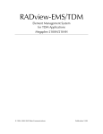
High-Density Applications
Figure 1-1 shows a typical application that utilizes the large number of links that
are supported by a DXC-30 chassis equipped with D8E1 modules: a DXC-30
chassis equipped with 14 D8E1 modules and one DE3 module can be used to
groom up to 112 fractional E1 links into one E3 link, all this within a 3U-high
enclosure which also includes redundant power supplies and redundant common
logic modules.
This capability enables the DXC-30 system to serve as the feeder for an E3
network, or to access channelized E3 ports of higher-order switches in the
plesiochronous (PDH) and synchronous (SDH) digital hierarchies.
1
2
E1 or
Fractional E1
Links
.
.
.
.
.
.
.
111
112
DXC-30
E3
Network
..
..
14 D8E1
Modules
DE3
Module
Figure 1-1. Typical High-Density Grooming Application for DXC-30
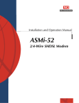
Figure 1-2 shows another application that illustrates the high density which can
be achieved with D4E1/D8E1 modules: a 1U-high DXC-8R chassis can be used to
provide T1/E1 conversion and cross-connect services for up to 32 links. For
example, the DXC-8R can be equipped with three D8E1 and one D8T1 modules to
provide conversion from up to 24 fractional E1 links into 8 T1 links, for
transmission through a T1 transport network.
1-2
Overview
D4E1, D8E1 Ver. 10.1
Installation and Operation Manual
1
2
Fractional
E1 Links
Chapter 1 Introduction
DXC-8R
..
..
..
.
T1
Transport
Network
1
...
..
.
8
23
24
D8E1
Modules
D8T1
Module
T1 Links
Figure 1-2. High-Density T1/E1 Conversion and Cross-Connect Application for DXC-8R
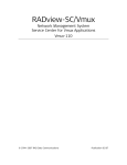
Figure 1-3 shows a 1U-high DXC-10A chassis used as an E3 multiplexer: for this
purpose, the DXC-10A chassis is equipped with one DE3 and two D8E1 modules.
The two additional slots of the DXC-10A chassis can then be used to provide
other services.
1
2
E1 or
Fractional E1
Links
DXC-10A
..
..
..
.
E3
Network
..
.
15
16
D8E1
Modules
DE3
Module
E3 Link
Figure 1-3. E3 Multiplexer Application for DXC-10A
Signaling Monitoring
The high port density of the D4E1/D8E1 modules allows another important DXC
application: signaling monitoring. The DXC collects signaling timeslots from many
leased lines and grooms them over a full link to the protocol analyzer at a central
site. The analyzer reads the signals that identify each user, checks the user
profile and activates the appropriate response.
The solution is based on a probe (passive T-sampler or patch panel) that
duplicates the traffic on each voice channel and sends it to the DXC. The DXC
extracts the signaling information from one or more timeslots of each voice
channel and grooms all the timeslots onto one output E1 or E3 line. The timeslots
are sent to the network management station at the central or regional office for
analysis. Data from these timeslots indicate the quality of the connection and
detect network faults. The same (or different) timeslots can be broadcast to
billing, security, fraud detector or other systems without adding line probes.
Additional destinations can be added at any time. The lines that connect the DXC
to the probe are configured as unidirectional, so as not to interfere with the
voice traffic passing on the line. Since the traffic is transparent to the DXC, it can
support any signaling protocol, provided that the signaling information resides in
the same timeslot of each E1 link.
Figure 1-4 and Figure 1-5 show a DXC-8R chassis equipped with the D8E1 module
in a signaling monitoring application, using a patch panel and a passive T-sampler,
respectively.
For details regarding the integration of the D4E1 and D8E1 modules in DXC
systems and additional system applications, refer to the DXC Installation and
Operation Manual.
D4E1, D8E1 Ver. 10.1
Overview
1-3
Chapter 1 Introduction
Installation and Operation Manual
Billing
1
D8E1 ModulesD8T1
E1 Links
31
Security
DXC-8R
Fraud Detection
Figure 1-4. Signaling Monitoring with Patch Panel Sampler
Billing
Security
D8E1 ModulesD8T1
Fraud Detection
DXC-8R
Figure 1-5. Signaling Monitoring with Passive T-Sampler
Note
1-4
Since high-density modules usually require more than two bus links, they have
been designed as modules with dynamic timeslot allocation. When designing a
DXC application with these modules, it is important to understand the Automatic
Timeslot Allocation for various DXC modules described in Chapter 3 of the DXC
Installation and Operation Manual and follow a number of important design and
configuration guidelines recommended by RAD. For design guidelines refer to
“Design Guidelines for a High-Density Module Application” (Chapter 3 of the DXC
Installation and Operation Manual). For configuration guidelines, refer to
“Checking for Free Timeslots” in Chapter 6.
Overview
D4E1, D8E1 Ver. 10.1
Installation and Operation Manual
1.2
Chapter 1 Introduction
Physical Description
D4E1 Module
Figure 1-6 shows the panel of the
D4E1 module.
D4E1
S. LOSS
LOC REM
1
2
The panel includes four RJ-45
connectors, one for each port.
A cable is available for providing an E1
unbalanced interface with BNC
connectors to the user equipment.
LEDs on the front panel indicate a local
or remote sync loss alarm for each line.
3
4
1
2
3
4
Figure 1-6. D4E1 Module Panel
D8E1 Module
Figure 1-7 shows the panel of the D8E1
module.
The panel includes one DB-44 female
connector.
For the balanced version, a cable is
available converting the DB-44
connectors to eight RJ-45 balanced
connectors.
D8E1
S. LOSS
LOC REM
1
2
3
4
5
6
7
8
For the unbalanced version, a cable is
available converting one DB-44
connector to 8 pairs of BNC unbalanced
connectors.
LEDs on the front panel indicate a local
or remote sync loss alarm for each line.
Figure 1-7. D8E1 Module Panel
D4E1, D8E1 Ver. 10.1
Physical Description
1-5
Chapter 1 Introduction
Installation and Operation Manual
1.3
Functional Description
Functional Block Diagram
Figure 1-8 shows the functional block diagram of the D8E1 module. The block
diagram of the D4E1 module version is similar, except that it does not include the
ports 5 through 8 and the associated circuits.
DXC Bus
E1 Receive
Clock
Generator
Address Bus
Fallback Clock
Control Bus
Data to I/O Modules from DCL
Data from I/O Modules to DCL
DCL-I/O Communication
D4E1/D8E1 Module
Main Clock
. Clock Signals
. Recovered from
.
. E1 Line Signals
Clock & Timing
Signals
Clock
Selection
BERT
Subsystem 1
LIU 1
External
Port 1
.
.
.
.
.
.
.
.
.
.
.
.
.
.
.
.
.
.
.
.
.
.
.
.
.
.
.
.
Framer 4
LIU 4
External
Port 4
BERT
Subsystem 5
Framer 5
LIU 5
.
.
.
.
.
.
.
.
.
.
.
External
Port 5
.
.
.
.
.
.
.
.
.
.
.
.
.
.
Framer 8
LIU 8
Framer 1
.
.
.
.
.
.
.
.
.
.
.
BERT
Subsystem 4
Bus
Interface
Routing
Memory
.
.
.
.
.
.
.
.
.
.
.
.
.
.
External
Port 8
Data
BERT
Subsystem 8
Address
On D8E1 Only
Control
Management
Subsystem
Figure 1-8. D4E1/D8E1 Functional Block Diagram
1-6
Functional Description
D4E1, D8E1 Ver. 10.1
Installation and Operation Manual
Chapter 1 Introduction
The D4E1 and D8E1 modules include the following main subsystems:
•
Bus interface subsystem
•
Line interface subsystem
•
Clock and timing subsystem
•
BERT subsystem
•
Management subsystem.
Bus Interface Subsystem
The function of the bus interface subsystem is to route the desired timeslots
between the DXC bus (the bus that carries the traffic of the other modules
installed in the DXC unit) and the appropriate E1 ports of the D4E1/D8E1 module.
In case of alarm conditions, the bus interface inserts appropriate user-specified
out-of-service (OOS) codes, provided by the module management subsystem.
The DXC bus includes two data buses:
•
Data from I/O bus - carries the data from I/O modules and D4E1/D8E1 to the
DCL module.
•
Data to I/O bus - carries data to I/O modules and D4E1/D8E1 from the DCL
module.
The bus interface operates as a non-blocking routing matrix that can map
timeslots from the DXC bus to any of the timeslots of the D4E1/D8E1 E1 ports.
The routing matrix is controlled by the DXC common logic subsystem (located in
the DCL module). The DXC common logic subsystem transmits the routing control
data to a routing memory that stores the local D4E1/D8E1 routing database, and
controls the operation of the matrix. This ensures that the operation of the
D4E1/D8E1 routing matrix is coordinated with the operation of the main crossconnect matrix located on the DCL module, and thus utilize in the most efficient
way the bandwidth of the DXC data bus (refer to Chapter 3 of the DXC
Installation and Operation Manual for a description of the DXC main routing
matrix and DXC bus).
Because of the large number of bus links needed to support four or eight module
ports, timeslot allocation for the module is in accordance with the Type 2
allocation as described in Chapter 3 of the DXC Installation and Operation Manual.
This means that the module supports both types of timeslot allocation available
on the DXC:
•
Dynamic allocation – bus bandwidth is automatically allocated in accordance
with the actual number of timeslots routed to each port. This approach
utilizes the bus bandwidth in the most efficient way, however it may cause
short disruptions in traffic (perceived by the users as short bursts of errors)
when bus timeslots are reassigned after inserting new modules or changing
the bandwidth (number of timeslots) assigned to modules.
•
Static allocation – bus bandwidth is permanently assigned to each port on
the basis of the maximum number of timeslots that are expected to be
routed to each port, in accordance with the planned traffic load. This
allocation is less efficient than dynamic allocation, because the number of
timeslots allocated to the port includes not only timeslots actually carrying
D4E1, D8E1 Ver. 10.1
Functional Description
1-7
Chapter 1 Introduction
Installation and Operation Manual
traffic, but also timeslots reserved for future growth. However, the
advantage of this method is that when timeslots reserved for a port are
allocated to traffic, there is no disruption to the traffic of other ports.
The timeslot allocation method used by the DXC (dynamic or static) is selected by
the user.
In addition to the routing of payload data, the D4E1 and D8E1 modules support
the allocation of one user-selectable timeslot to inband management.
Line Interface Subsystem
The line interface subsystem includes identical, independently operating E1 ports.
The number of ports, 4 or 8, depends on the module version.
Each port consists of two sections:
•
Framer. The transmit path of the framer generates the E1 frame structure
transmitted by the corresponding port, in accordance with the selected
framing mode. The frame structure is generated by combining the data
transferred by the bus interface from the DXC bus with the CAS and framing
overhead, and when applicable - with the inband management data stream
(received through the microprocessor interface). Unused timeslots are filled
with the user-specified idle code, provided by the module framers.
The receive path of the framer demultiplexes the incoming E1 data stream,
and extracts the payload data, CAS signaling information, and when
applicable - the inband management data stream. The framer also collects
performance statistics based on framing errors and errors detected by the
CRC-4 monitoring function, which can be read by the DCL module through the
module management subsystem.
•
LIU (line interface unit). The LIU provides the interface to the external E1 line,
and therefore its characteristics (nominal line impedance and signal levels)
depend on the connection cable.
The transmit path of the LIU includes an HDB3 coder, which converts the NRZ
transmit data stream provided by the E1 framer to the line code specified for
use on E1 links, and then generates the E1 transmit signal in accordance with
ITU-T Rec. G.703.
The receive path of the LIU recovers the received E1 signal and the associated
clock signal. The recovered E1 signal is decoded by an HDB3 decoder, and
sent to the receive path of the E1 framer in NRZ format. The receive path
characteristics can emulate either as a DSU or LTU, as selected by the user in
accordance with the required range.
The HDB3 decoder can provide performance statistics for evaluating line
transmission quality when the CRC-4 option is not used, by collecting data on
the bipolar violations (BPVs) detected in the incoming signal.
Clock and Timing Subsystem
This subsystem provides the clock and timing signals required by the D4E1/D8E1
module, and enables the user to select the recovered clock signal of one of the
module E1 ports as the timing reference for the DXC master (nodal) clock.
1-8
Functional Description
D4E1, D8E1 Ver. 10.1
Installation and Operation Manual
Chapter 1 Introduction
D4E1/D8E1 timing is derived as follows:
•
The timing of the transmit paths of all the E1 ports is always locked to the
DXC master clock, received through the control bus, part of the DXC bus.
•
The timing of the receive paths of the E1 ports is always derived from the
clock signal recovered from the incoming line signal.
The D4E1/D8E1 module includes a clock generator that generates two clock
signals. Each of the two clock signals can be locked to the DXC master clock.
The two signals provided by the clock generator, which are connected to the
control bus, can be selected as main and fallback timing references for the DXC
master clock, thereby locking the DXC master clock to the timing of the
corresponding E1 port.
BERT Subsystem
Each E1 port has its own BERT subsystem, which can be used to test the
operation of each E1 port, and data transmission through the line connected to
that port.
When the BER test is enabled on one of the D4E1/D8E1 ports, the bus interface
disconnects that port from the DXC bus. During the test, the transmit signal is
provided by the BER test sequence generator, in accordance with the BER testing
parameters selected by the user. The received signal is applied to the test
sequence evaluator, which detects the errors.
The error data is sent to the DCL module through the D4E1/D8E1 management
subsystem.
Management Subsystem
The management subsystem controls the operation of the D4E1/D8E1 module,
under the control of the DCL module. The management and supervision data is
exchanged through the address and control buses, part of the DXC bus.
When inband management is enabled, the management subsystem transmits and
receives management traffic through microprocessor interface. In this case, the
management traffic exchanged through the port interfaces is transferred to the
DCL module through an internal port, operating at a data rate of 64 kbps.
E1 Port Interface Characteristics
The E1 port interfaces of the D4E1/D8E1 module meet the applicable
requirements of ITU-T Rec. G.703, G.704, G.706, G.732 and G.823.
Framing
The E1 port interfaces support both G732N and G732S multiframes (2 or 16
frames per multiframe, respectively), or unframed 2 Mbps data flow as per ITU-T
Rec. G.703, in accordance with user's selection. The user can also select the
frame synchronization algorithm: standard (in accordance with ITU-T Rec. G.704),
in accordance with AT&T TR-62411, or a proprietary fast algorithm.
D4E1, D8E1 Ver. 10.1
Functional Description
1-9
Chapter 1 Introduction
Installation and Operation Manual
The port interfaces also supports the CRC-4 option, as specified in ITU-T Rec.
G.704, thereby enabling the monitoring of the links to the DXC.
The framing mode and CRC-4 use are user-programmable, separately for each
port.
Physical Interface
D4E1/D8E1 modules use the HDB-3 line code. Jitter performance complies with
the requirements of ITU-T Rec. G.823.
The D4E1/D8E1 E1 port interfaces have integral LTUs for long-haul operation,
covering line attenuations up to 36 dB. For short-haul operation, the user can
configure the port interface to emulate a DSU (in this case, the maximum line
attenuation is 10 dB).
For monitoring applications, the receiver provides gain of 12 dB or 30 dB
(software-selectable) to overcome the resistive loss of the monitor connection,
along with 0 to 6 dB of cable attenuation.
Port Routing Mode
To expedite the handling of the E1 data streams (in particular those multiplexed
into E3 or T3 data streams), the user can specify the routing mode of each
module ports:
•
Regular Routing - in this mode, the routing subsystem can independently
route the individual timeslots of the port. This mode supports the timeslot
cross-connect function, and therefore the timeslots of an E1 port using
regular routing can also be routed to other types of I/O modules, such as
DE1B, DT1B, DIM, DE3, DT3 or DHS modules.
This mode enables the transmission of a full E1 data stream from a module
port through another E1 port located on any module with E1 ports, including
internal E1 ports of an E3 module; it also enables the transmission of a full T1
data stream received from another I/O module with T1 ports (including the
F-bit) through an E1 link, in accordance with ITU-T Rec. G.802.
•
Transparent Routing - in this mode, the routing subsystem transparently
transfers the whole frame structure (including timeslot 0 and timeslot 16),
toward another E1 port, including an internal E1 port of a DE3 module. The
other port must also use the transparent mode.
The regular routing mode is suitable for data traffic, for which it is not necessary
to support end-to-end transmission of channel-associated signaling. In addition,
when transmitting inband management traffic through the E1 link in a dedicated
timeslot, the E1 port that carries the management timeslot must always be
configured for regular routing.
The transparent mode enables the transmission of an E1 data stream carrying
voice traffic, because it preserves the original E1 multiframe structure.
1-10
Functional Description
D4E1, D8E1 Ver. 10.1
Installation and Operation Manual
Chapter 1 Introduction
Handling of National Bits
The D4E1/D8E1 modules enable the user to control the handling of the national
bits, Sa4 through Sa8, in timeslot 0.
For each port, the user can select the utilization and state of each bit, in
accordance with the following options:
•
Transfer of management traffic: when the inband management traffic is
carried in timeslot 0, the user can select the Sa bits that will carry the traffic.
•
Transparent transfer of the desired bits.
•
Setting of any bit to the desired fixed value, “0” or “1”.
Handling of Alarm Conditions
The E1 ports support two types of indications in the individual timeslots: idle
timeslots and out-of-service (OOS) indications.
•
Idle Timeslot Indication. A special code can be transmitted in empty timeslots
(timeslots which do not carry payload).
•
OOS Indications. The OOS code is inserted in individual timeslots to signal the
equipment routed to one of the E1 ports of the module that the link
connected to the external port is out-of-service (e.g., because of the
reception of AIS, loss of signal, loss of frame synchronization). All the ports
use the same OOS code.
For a complete description of alarm handling in the DXC system, refer to
Section 3.5 in the DXC Installation and Operation Manual.
Diagnostics
To reduce downtime to a minimum, the D4E1/D8E1 module includes self-test
upon power-up, and additional testing and diagnostic functions that can be
controlled by means of the management functions supported by the DXC system
(supervision terminal, SNMP or Telnet).
Test and Loopback Functions
The testing capabilities include the following types of loopbacks:
•
Local loopback: the output signal of the E1 port is looped back to the input,
and is returned toward the local DXC.
•
Remote loopback: the signal received by the E1 port is regenerated and
looped back to the transmit path of the port, and then returned toward the
remote equipment. The remote loopback can also be activated on individual
timeslots by transmitting the FT1 inband loopback activation code (remote
timeslot loopback).
•
BER testing: to enable testing of marginal links, the D4E1/D8E1 module
supports bit error rate (BER) testing on each port, using a locally generated
pseudorandom sequence.
D4E1, D8E1 Ver. 10.1
Functional Description
1-11
Chapter 1 Introduction
Installation and Operation Manual
To provide compatibility with other BER testing equipment, the user can
select the pseudorandom pattern.
Performance Diagnostics
The D4E1/D8E1 supports the collection of performance diagnostics, using the
CRC-4 function. The collected performance data is similar to the requirements of
AT&T Pub. 54016.
If the CRC-4 function is disabled, a D4E1/D8E1 port can still provide diagnostic
information on bipolar violations detected at the port.
1.4
General
Technical Specifications
Function
E1 multi-port I/O module
Number of Ports
E1 Port
Characteristics
D4E1
4 E1 ports
D8E1
8 E1 ports
Data Rate
2.048 Mbps ±50 ppm
Framing Options
G.732N, G.732S with or without CRC-4 protection in
accordance with ITU-T Rec. G.704
Unframed as per G.703
Applicable Standards
ITU-T Rec. G.703, G.704, G.706, G.732, G.823
Interface Options
Software-selectable
Short Haul (DSU)
-10 dB maximum line attenuation
Long Haul (LTU)
-36 dB maximum line attenuation
Monitoring Mode
Software-selectable:
• 20 dB gain to compensate resistive attenuation
• 32 dB gain to compensate resistive attenuation
Line Code
HDB3
Unbalanced E1 Port (UNBAL Option)
1-12
Line Impedance
75Ω
Pulse Shape
ITU-T Rec. G.703
Technical Specifications
D4E1, D8E1 Ver. 10.1
Installation and Operation Manual
Chapter 1 Introduction
D4E1 Connectors
Four pairs of 1.0/2.3 mm female connectors (one pair
for each port)
D8E1 Connectors
Eight pairs of 1.0/2.3 mm female connectors, or two
25-pin D-type female connectors for all module ports
Balanced E1 Port (BAL Option)
Timing
Line Impedance
120Ω
Pulse Shape
ITU-T Rec. G.703
D4E1 Connectors
Four RJ-45 connectors (one for each port)
D8E1 Connectors
Eight RJ-45 connectors, one for each port, or two
25-pin D-type female connectors for all module ports
Port Timing
• Receive timing recovered from incoming line signal
• Transmit timing locked to the DXC master clock
• DXC master clock can be locked to one of the
recovered internal E1 port clock signals
Diagnostics
Loopbacks
• User-activated local and remote loopback on each
E1 port
• Remote loopback activation by inband FT1 code
Indicators
Performance
Monitoring
RFC 2495 (substitutes RFC 1406)
S LOSS LOC (red)
Local signal loss for each module port
S LOSS REM (red)
Remote signal loss for each module port
Physical
Power
Consumption
Occupies a single DXC module slot
D4E1
5.5W (1.1A)
D8E1
7.25W (1.45A)
Timeslot
Allocation
• Sequential
Configuration
Programmable via DXC management
D4E1, D8E1 Ver. 10.1
• User-defined, any timeslot to any timeslot mapping
Technical Specifications
1-13
Chapter 1 Introduction
1-14
Technical Specifications
Installation and Operation Manual
D4E1, D8E1 Ver. 10.1
Chapter 2
Installation and Setup
2.1
Introduction
This chapter provides installation and operation instructions for the D4E1 and
D8E1 modules.
The information presented in this chapter supplements the general installation
and operation instructions contained in the DXC Installation and Operation
Manual.
Warning
Before performing any internal settings, adjustment, maintenance, or repairs,
first disconnect all the cables from the module, and then remove the module
from the DXC enclosure.
No internal settings, adjustment, maintenance, and repairs should be performed
by either the operator or the user; such activities should be performed only by a
skilled technician who is aware of the hazards involved.
Always observe standard safety precautions during installation, operation, and
maintenance of this product.
Caution The D4E1 and D8E1 modules contain components sensitive to electrostatic
discharge (ESD). To prevent ESD damage, always hold a module by its sides, and
do not touch the module components or connectors.
2.2
Installing the Module in the DXC Enclosure
The D4E1/D8E1 modules do not have any user settings, and therefore no
preparations are required before installation.
Revise the system installation plan and Section 6.3, “Checking for Free I/O Slots”,
of the DXC Installation and Operation Manual and insert the module in the
assigned I/O slot of the DXC enclosure. The module starts operating as soon as it
is plugged into an operating enclosure.
D4E1, D8E1 Ver. 10.1
Installing the Module in the DXC Enclosure
2-1
Chapter 2 Installation and Setup
2.3
Installation and Operation Manual
Connecting the Module Ports
Module Connectors
Module Versions with RJ-45 Connectors
For these module versions, each port interface is terminated in an eight-pin RJ-45
connector, wired in accordance with Table 2-1.
Table 2-1. RJ-45 Port Connector, Pin Assignment
Pin
Pin Function
1
Receive Input (ring)
2
Receive Input (tip)
3
Frame Ground
4
Transmit Output (ring)
5
Transmit Output (tip)
6
Frame Ground
7, 8
Not Connected
Note
Pins not listed in the table are not connected.
Module Versions with DB-44 Connectors
For these module versions, each port interface is terminated in a 44-pin DB-44
connector, wired in accordance with Table 2-2.
2-2
Connecting the Module Ports
D4E1, D8E1 Ver. 10.1
Installation and Operation Manual
Chapter 2 Installation and Setup
Table 2-2. DB-44 Port Connector, Pin Assignment
Pin
Function
Pin
Function
Pin
Function
Pin
Function
1
CH-1 TX Tip
22
CH-5 TX Ring
9
CH-6 TX Tip
35
CH-4 RX Ring
2
CH-2 TX Ring
23
CH-5 RX Tip
10
CH-7 TX Tip
36
CH-4 RX Tip
3
CH-2 TX Tip
25
CH-7 TX Ring
11
CH-8 TX Ring
37
CH-5 RX Ring
4
CH-3 TX Tip
26
CH-7 RX Tip
12
CH-8 TX Tip
38
CH-6 RX Ring
5
CH-4 TX Ring
31
CH-1 RX Ring
16
CH-1 TX Ring
39
CH-6 RX Tip
6
CH-4 TX Tip
32
CH-2 RX Tip
17
CH-1 RX Tip
40
CH-7 RX Ring
7
CH-5 TX Tip
33
CH-2 RX Ring
19
CH-3 TX Ring
41
CH-8 RX Ring
8
CH-6 TX Ring
34
CH-3 RX Ring
20
CH-3 RX Tip
42
CH-8 RX Tip
Connecting Cables to the Module Ports
When the D4E1, D8E1 module operates, the module connector supports both
balanced and unbalanced interfaces. For D4E1 every port is independent and can
be balanced or unbalanced depending on the type of cable connected.
For D8E1, only one type of interface can be active (the interface is selected by
the user): balanced or unbalanced. Each type requires a different adapter cable:
•
CBL-G703-8/RJ45: this cable is used for balanced E1 interfaces
•
CBL-G703-8/COAX: this cable is used for unbalanced E1 interfaces.
The port can automatically detect the type of adapter cable connected to the
port cable: if the cable does not match the configured interface, an alarm is
generated.
Table 2-3 shows the different types of cables required for making the
connections to D4E1, D8E1 modules.
Table 2-3. D4E1, D8E1 Cables
Interface
Type
D4E1
D8E1
Balanced
RJ-45 to RJ-45 (4
cables)
DB-44 to 8 × RJ-45 (one cable assembly)
RAD part number: CBL-G703-8/RJ-45
Unbalanced
RJ-45 to BNC (4 cables)
DB-44 to 8 × BNC (one cable assembly)
RAD part number: CBL-G703-8/COAX
Using the site installation plan, identify the cable intended for connection to the
D4E1, D8E1 connector, and connect the cable to the module connector as
explained below.
D4E1, D8E1 Ver. 10.1
Connecting the Module Ports
2-3
Chapter 2 Installation and Setup
³
Installation and Operation Manual
To connect the cable to the balanced E1 interface:
1. For D4E1, connect the RJ-45 connector to the D4E1 front panel port.
2. For D8E1, connect the 44-pin connector of cable CBL-G703-8/RJ45 to the
D8E1 front panel connector.
3. Connect the RJ-45 plug of each port interface (D8E1 plugs are marked CH-1
to CH-8) to the prescribed user’s equipment or patch panel connector.
Insulate unused connectors, to prevent accidental short-circuiting of their
exposed contacts to metallic surfaces.
³
To connect the cable to the unbalanced E1 interfaces:
1. For D4E1, connect the RJ-45 connector to the D4E1 front panel port.
2. Connect the 44-pin male connector of the cable CBL-G703-8/COAX to the
D8E1 front panel connector.
3. Connect the BNC plugs of each port interface (the plugs are marked with the
number of the port) to the prescribed user’s equipment or patch panel
connectors. Pay attention to correct connection:
2-4
TX connector serves as the transmit output of the port
RX connector serves as the receive input of the port.
Connecting the Module Ports
D4E1, D8E1 Ver. 10.1
Chapter 3
Configuration
This chapter provides configuration information for the D4E1 and D8E1 modules.
The configuration activities are performed by means of the management system
used to control the DXC unit.
The instructions appearing in this chapter assume that you are familiar with the
management system being used: a supervision terminal or Telnet (covered by the
DXC Installation and Operation Manual), or a network management system, e.g.,
the RADview network management system (refer to the RADview User's Manual
for instructions).
3.1
Outline of Configuration Procedure
The configuration procedure for a new D4E1/D8E1 module includes the following
main steps:
• Inclusion of a D4E1/D8E1 module not yet installed in the DXC into the DXC
database. It permits to preprogram the module parameters, so when the
module is installed in the enclosure it will immediately start operating in the
desired mode. This function is performed by means of the DEF SYS command.
• Configuration of the external port parameters of the D4E1/D8E1 module, using
the DEF PORT A:B command, where A is the D4E1/D8E1 slot number, and B is
the port number.
• Configuration of the internal port parameters of the D4E1/D8E1 module, using
the DEF PORT A:i1 command, where A is the D4E1/D8E1 slot number.
In addition to the configuration functions listed above, you can display specific
status information on the module external ports, using the DSP ST and DSP CON
commands. Starting from version 7.1 (DCL.3 common logic), you can use the DSP
TS UTILIZATION and DSP TS ALLOC commands to display the timeslot
utilization percentage and the number of timeslots free for use on the port,
module and system levels for all the ports of the Type 2 modules installed in the
system.
D4E1, D8E1 Ver. 10.1
Configuration Instructions
3-1
Chapter 3 Configuration
Installation and Operation Manual
3.2
Configuration Instructions
Starting a Configuration Session
If the supervision terminal is not yet connected to the DXC, connect the terminal
and start a configuration session in accordance with the instructions appearing in
Chapter 5 of the DXC Installation and Operation Manual.
Inclusion of D4E1/D8E1 Module in Database
The DXC system automatically identifies the installed modules, therefore skip this
step if the D4E1/D8E1 module to be configured is already installed in the
equipment chassis.
1. If the D4E1/D8E1 module to be configured is not yet installed in the DXC,
type:
DEF SYS<Enter>
2. The system parameters data form is displayed. A typical data form for a
DXC-30 is shown below (other DXC versions differ only in the number of slots
to be configured). The form presents the current parameter values as
defaults.
CLK_MASTER
INT
CLK_FBACK
NONE
REDUNDANCY
NO
STATION_CLOCK MATRIX_MODE
2.048MHz
BIDIRECT
DATE_FORMAT
DD/MM/YYYY
3. Assuming that the only necessary change is the inclusion of a new D4E1 or
D8E1 module in the system database, press <Enter>. For the DXC with DCL.3
common logic, versions 7.1 and higher, the second line of the system
parameters data form is displayed. The second line controls the DXC timeslot
allocation method (static, static 1:1 or dynamic – see description in Appendix
F of the DXC Installation and Operation Manual, DEF SYS command) and the
station clock interface type. A typical form is shown below.
TS_ALLOC_MODE
STATION_CLOCK_IF
STATIC
G703
4. After the desired parameter values are selected, press <Enter>. The next line
of the system parameters data form is displayed. A typical data form for a
DXC-30 is shown below:
IO :
TYPE:
NO 1
D4E1
NO 2
D8E1
NO 3
DT1_DSU
NO 4
D4E1
NO 5
DE1_LTU
5. Change the module type for each desired slot.
To change the module installed in a specific slot, bring the cursor to the
beginning of the field (slot) to be changed by pressing the spacebar, and then
press <F> or <B> to scroll among the available selections. When the desired
selection is displayed, press the spacebar to move to the next field.
6. After the desired module types are defined, press <Enter>. The fourth line of
the DXC-30 system parameters data form, which covers the I/O slots 6
through 10, is displayed.
3-2
Configuration Instructions
D4E1, D8E1 Ver. 10.1
Installation and Operation Manual
Chapter 3 Configuration
Repeat the procedure described above to change the modules types as
required, and then press <Enter> to display the fifth, and last, line, which
covers the I/O slots 11 through 15. A typical last line of the system
parameters data form is shown below:
IO :
TYPE:
NO 11
DIM
NO 12
DHS
NO 13
DE1_DSU
NO 14
DT1_CSU
NO 15
DHS
7. Change the module type for each slot as described above, and then press
<Enter> to end.
Configuration of External Port Parameters
To configure the parameters of an external D4E1/D8E1 port, type:
DEF PORT A:B<Enter>
where:
• A is the D4E1/D8E1 slot number (1 through 15 for the DXC-30, 1 through 5
for the DXC-10A, and 1 through 4 for the DXC-8R)
• B is the external port number (1 through 4 for D4E1, and 1 through 8 for
D8E1).
First Page of Internal Port Parameters
You will see the first page of the external port parameters data form. A typical
page is shown below:
FRAME
G732N
CRC-4
NO
SYNC
CCITT
LINK_MODE
REGULAR
RX_GAIN_LIMIT
SHORT_HAUL
SA4
SA5
SA6
SA7
SA8
TRANS TRANS TRANS TRANS TRANS
The parameters included on the first page are explained in Table 3-1.
Table 3-1. First Page of External Port Parameters
Parameter
Function
Values (Default shown in bold)
FRAME
Determines the framing method
used by the selected external port
G732N
256N frame per ITU-T Rec. G.704 (2 frames
per multiframe).
G732S
256S frame per ITU-T Rec. G.704 (16 frames
per multiframe).
UNFRAMED Unframed 2 Mbps data flow as per ITU-T Rec.
G.703
CRC-4
Enables the generation of check
bits (in accordance with the CRC-4
polynomial specified by ITU-T
Rec. G.704) for the frames
transmitted on the selected
external port, and the checking of
the check bits carried by the
received frames
D4E1, D8E1 Ver. 10.1
NO
CRC-4 option disabled.
YES
CRC-4 option enabled.
Configuration Instructions
3-3
Chapter 3 Configuration
Installation and Operation Manual
Parameter
Function
Values (Default shown in bold)
SYNC
Changes the synchronization
algorithm used by the selected
external port, to reduce the time
required for the port to return to
normal operation after local loss of
synchronization.
CCITT
Complies with ITU-T Rec. G.732
62411
In accordance with AT&T TR-62411 (after
10 seconds).
FAST
After 1 second.
This parameter controls the
handling of traffic routed to the
selected external port within the
D4E1 or D8E1 module
REGULAR
Enables independent routing of each
timeslot. This selection enables the timeslot
cross-connect function on the D4E1/D8E1
module, and therefore the timeslots of an
E1 port using regular routing can also be
routed to other types of I/O modules, e.g.,
E1, T1, DIM, DE3, DT3 or DHS modules.
LINK_
MODE
Use this selection for routing data timeslots.
TRANS
Enables transparent transfer of the whole
E1 frame structure (including timeslots 0
and 16 for E1 frames), toward the external
port (supported by DXC systems with
software release 5 and higher).
Use this selection to enable the
transmission of the full E1 data stream
received from an internal E1 interface of a
DE3 I/O module through this port. This is
required to carry voice traffic.
RX GAIN
LIMIT
Determines the maximum
SHORT HAUL
attenuation of the receive signal
that can be compensated for by
LONG HAUL
the port receive path, to obtain the
BER performance required by the
standards
Maximum attenuation of 10 dB, relative to the
nominal transmit level.
Maximum attenuation of 36 dB, relative to the
nominal transmit level.
The lower attenuation may actually improve
the performance when operating over
relatively short line sections, especially when
operating over multi-pair cables. In such
cables, significant interference is generated
by the signals carried by other pairs, and
therefore a weak desired signal may be
masked by the interference.
MONITOR+12 The receiver provides gain of 12 dB to
overcome the resistive loss of the monitor
connection, along with 0 to 6 dB of cable
attenuation
MONITOR+30 The receiver provides gain of 30 dB to
overcome the resistive loss of the monitor
connection, along with 0 to 6 dB of cable
attenuation
3-4
Configuration Instructions
D4E1, D8E1 Ver. 10.1
Installation and Operation Manual
Chapter 3 Configuration
Parameter
Function
Values (Default shown in bold)
SA4
Controls the handling of the
MGMT
national bit S by the corresponding
port.
The S bit is used to carry inband management
traffic (this option is required when the
INB_MNG parameter is TS0/F).
This field is displayed only when
the LINK_MODE is REGULAR
The S bit is transferred transparently to the
S bit of an adjacent port of the D4E1/D8E1
module (e.g., ports 1-2, 3-4, 5-6 or 7-8).
a4
a4
TRANS
a4
a4
ZERO
The S bit is set to “0” before it is transferred
to the S bit of the external E1 interface.
a4
a4
ONE
SA5
Same as above, except the S bit is set to “1”.
a4
Controls the handling of the
Same options as for SA4
national bit S by the corresponding
port
a5
Same options as for SA4
Controls the handling of the
national bit S by the corresponding
port
SA6
a6
SA7
Controls the handling of the
Same options as for SA4
national bit S by the corresponding
port
a7
Same options as for SA4
Controls the handling of the
national bit S by the corresponding
port
SA8
a8
To change the displayed parameters, bring the cursor to the beginning of the
field to be changed by pressing the spacebar, and then press F or B to scroll
among the available selections. When the desired selection is displayed, press the
spacebar to move to the next field.
When done, press <Enter> to display the next page.
Second Page of External Port Parameters
You will see the second page of the external port parameters data form. A typical
page is shown below:
CGA
TRANS
IDLE_TS_CODE
7E
OOS_SIG
SPACE
VOICE_OOS
00
DATA_OOS
00
INB_MNG
NONE
ROUTE_PROT
NONE
The parameters included on the second page are explained in Table 3-2.
Table 3-2. Second Page of External Port Parameters
Parameter
Function
Values (Default shown in bold)
CGA
Selects the method used to
signal the carrier group alarm
(CGA) state (link
out-of-service) to the other
end of the selected link
NONE
D4E1, D8E1 Ver. 10.1
When a link is in the out-of-service state, the
timeslots carry the appropriate OOS code (data or
voice OOS code, in accordance with the type
selected for each timeslot). In addition, for links
with G.732S framing the signaling bits A, B also
assume the OOS state, and signaling bits C and D
assume the state 0 and 1, respectively.
Configuration Instructions
3-5
Chapter 3 Configuration
Parameter
Function
Installation and Operation Manual
Values (Default shown in bold)
TRANS
Same as for NONE, but the signaling bits are not
forced to the OOS state. Used for voice
applications with common channel signaling
(proprietary signaling) and for channelized data
applications.
FULL
The state of the timeslots and state of the
signaling bits is not changed. This mode is the
fully-transparent mode, and is often used when
the link carries channelized or unchannelized
data.
IDLE_TS_
CODE
Selects the code transmitted
to fill idle (unused) timeslots
in the frames transmitted
through the selected external
port
The available selections are 00 to FF (hexa).
OOS
SIGNALING
When NONE is selected for
the CGA parameter, this
parameter determines the
state of the signaling bits
during out-of-service periods
SPACE
The A and B signaling bits are forced to "1" during
out-of-service periods.
MARK
The A and B signaling bits are forced to "0" during
out-of-service periods.
SP_MK
The A and B signaling bits are forced to "1" for
2.5 sec, then switch to the "0" state until the
out-of-service condition disappears.
MK_SP
The A and B signaling bits are forced to "0" for
2.5 sec, then switch to the "1" state until the
out-of-service condition disappears.
Default: 3F
VOICE OOS
When NONE or TRANS has
The available selections are 00 to FF (hexa).
been selected for CGA, selects Default: 00
the code transmitted during
out-of-service periods on the
timeslots defined as voice
timeslots
DATA OOS
When NONE or TRANS has
The available selections are 00 to FF (hexa).
been selected for CGA, selects Default: 3E
the code transmitted during
out-of-service periods on the
timeslots defined as data
timeslots
3-6
Configuration Instructions
D4E1, D8E1 Ver. 10.1
Installation and Operation Manual
Chapter 3 Configuration
Parameter
Function
Values (Default shown in bold)
INB_MNG
Controls the transfer of
inband management traffic
through the selected external
port.
NONE
Transfer of management traffic is disabled. Always
select this option when the selected port is
configured for the TRANS (transparent) link mode,
because this mode requires one- to-one mapping of
timeslots to the source port.
TS0/F
Transfer of management traffic is enabled. The
management traffic is transferred using the
national bits, Sa4 through Sa8.
For a description of the
DEDIC
various traffic routing options,
refer to Inband Management
Traffic Routing in Section C.4 D-PPP
of the DXC Installation and
Transfer of management traffic is enabled. The
management traffic is transferred in a dedicated
timeslot, using a RAD proprietary protocol.
The D-PPP and D-FR traffic
routing options are generally
used with the RIP2 routing
protocol.
Operation Manual
D-FR
Transfer of management traffic is enabled. The
management traffic is transferred in a dedicated
timeslot, using synchronous PPP HDLC
encapsulation.
Transfer of management traffic is enabled. The
management traffic is transferred in a dedicated
timeslot, using frame relay encapsulation (under DLCI
100) in accordance with RFC 1490.
Note: The inband management data rate is as follows:
•
For the TS0 method, the supported data rates are 4 kbps (use of only one Sa bit), 8 kbps (two Sa bits),
12 kbps (three Sa bits), 16 kbps (four Sa bits), and 20 kbps (all the five Sa bits).
•
For the DEDIC, D-PPP, and D-FR, the supported data rate is 64 kbps.
ROUTE_PROT
This field controls the
NONE
transmission of routing tables, PROPRIET
which enable the use of
routing for management
RIP-II
traffic carried through this
port
Routing not supported.
Routing of management traffic by means of the
RAD proprietary protocol.
Management traffic is also routed using the RIP2
protocol.
Change the displayed parameters as necessary using the procedure explained
above. When done, press <Enter> to display the next page.
Third Page of External Port Parameters
If you have selected the static timeslot allocation mode under the DEF SYS
command, you will see the following typical page, which includes a single
parameter:
MAX_TS
05
The MAX_TS parameter is used to select the maximum number of timeslots that
may be connected on the selected port, without causing any disruption to the
traffic carried by other modules.
D4E1, D8E1 Ver. 10.1
Configuration Instructions
3-7
Chapter 3 Configuration
Note
Installation and Operation Manual
If you modify the MAX_TS parameter, the following warning appears: WARNING
118: CHANGE OF USED TS MAY CAUSE DATA ERROR BURST. This means that when
you perform the UPD DB command, data error burst is possible.
The allowed range is 1 through 31. If the FRAME parameter is UNFRAMED, the
MAX_TS parameter is automatically set to 32, and cannot be changed.
Change the parameter if necessary using the procedure explained above. When
done, press <Enter> to display the next page.
Port Timeslot Connection Data Form
You will see the next page of the external port parameters data form. This page
is used to select the timeslot mapping mode, and to define the type of timeslots
and the mapping parameters in case the sequential mapping mode has been
selected.
Note
When using the TRANS (transparent) link mode, you must map all the link
timeslots one-to-one to the source port. Therefore, you cannot enable inband
management for a port configured for the TRANS link mode.
A typical page is shown below:
MAP_MODE
SEQ
START_TS
03
NUM_OF_TS
14
DEST_PORT
04:02
TYPE
DATA
DEST_START_TS
06
The parameters included on the third page are explained in Table 3-3.
Table 3-3. External Port Timeslot Connection Parameters
Parameter
Function
Values (Default shown in bold)
MAP_MODE
Selects the timeslot mapping mode for this
port.
SEQ
Sequential mapping. In this mode, the
bundle of timeslots defined by the
START_TS and NUM_OF_TS parameters
is routed to the destination port, and
is assigned consecutive timeslots,
starting with the timeslot defined by
the DEST_START_TS parameter.
USER
Timeslots individually mapped by the
user.
The selection of a timeslot mapping mode is
individually made for each port, and does not
affect the timeslot mapping mode used on any
other port: for example, when the SEQ mode is
selected on one port (this mode enables you
to route a bundle of timeslots), and that port
is routed to a destination port whose mapping
mode is USER, the timeslot mapping mode
used at the destination port is not changed to
SEQ
START_TS
NUM_OF_TS
3-8
This parameter is applicable only when the SEQ
mode is selected. Its function is to indicate the
number of the first timeslot in the bundle of
timeslots taken from the frames transferred
through this port that is to be routed to the
destination port
The allowed range of timeslots is 1 through 31
This parameter is applicable only when the SEQ
mode is selected. Its function is to indicate the
number of the timeslots to be routed between
The allowed range of timeslots is 1 through 31.
Configuration Instructions
Default: 01
Note: If the value of NUM_OF_TS you have
D4E1, D8E1 Ver. 10.1
Installation and Operation Manual
Parameter
Function
Values (Default shown in bold)
the source and the destination ports.
specified exceeds the value of MAX_TS
parameter, the following warning appears:
ERROR 116: CONFLICT IN NUM OF ALLOCATED
TS AND MAX_TS.
When selecting the number of timeslots, it is
necessary to consider the starting timeslot, and
the total number of timeslots available on the
destination port (e.g., when the destination
port is a T1 port, the maximum number of
timeslots is 24)
DEST_PORT
Chapter 3 Configuration
This parameter is applicable only when the SEQ
mode is selected. Its function is to indicate the
destination port
The destination port is entered in the format A:B,
where:
A is the destination slot number (1 through 15 for
the DXC-30, 1 through 5 for the DXC-10A, and 1
through 4 for the DXC-8R).
B is the destination port number, 1 to 30.
Note: Only E1 and T1 ports can be selected as destinations: if you wish to map timeslots to a D8U, DHS, D8HS or
DIM port, then start the mapping from the configuration screens of the DHS, D8HS, DIM or D8U port (for detailed
instructions, refer to Chapter 3 of the corresponding Installation and Operation Manual).
TYPE
This parameter is used to define the handling of NC
the timeslots transferred to the destination port
D4E1, D8E1 Ver. 10.1
Timeslot is not connected, and
therefore carries the idle code.
DATA
The timeslots will be handled as data
timeslots. This does not preclude the
transfer of timeslots carrying voice
traffic, provided the equipment
connected to the port does not need
the conversion services offered by
the DXC for voice timeslots.
MGMT
This timeslot is dedicated to
management traffic. The selection is
available only for D4E1/D8E1
modules installed in a DXC system
with DCL.3 module, when the DEDIC,
D-PPP, or D-FR inband management
mode is selected, and the timeslot
assignment mode is USER.
VOICE
The data carried in the timeslot is
handled as a voice channel.
Therefore, when the timeslot is
connected to a T1 timeslot, the DXC
performs automatically μ-law to
A-law conversion.
VC-MP
Similar to VOICE, except that the A
and B signaling bits are not inverted
when the timeslot is connected to a
T1 link.
Configuration Instructions
3-9
Chapter 3 Configuration
Parameter
Installation and Operation Manual
Function
DEST_START_TS This parameter is applicable only when the SEQ
mode is selected. Its function is to indicate the
number of the first timeslot of the destination
frame to which the bundle of timeslots being
transferred is to be mapped
Values (Default shown in bold)
The allowed range of timeslots is 1 through 24
for routing to a T1 port, or 1 through 31 for
routing to an E1 port.
When selecting this number, it is necessary to
consider the number of mapped timeslots, the
mapping method (sequential), and the total
number of timeslots available on the destination
port (e.g., when the destination port is a T1 port,
the maximum number of timeslots is 24 or 25,
when the F-bit is also transmitted)
Change the displayed parameters as necessary using the procedure explained
above. When done, press <Enter>:
•
If the MAP_MODE is SEQ, after pressing <Enter> command entry is ended.
•
If the MAP_MODE is USER, after pressing <Enter> you will see the first page of
the timeslot map.
SEQ Mapping Example
For example, suppose that the DXC system is configured for operation in the
bidirectional mode, and the initial timeslot allocation from port 1:1 to port 3:1 is
as follows:
•
Start timeslot: 1
•
Number of timeslots: 20
•
Type: data
•
Destination timeslot: 1.
In this case, the timeslots 1:1:1 through 1:1:20 would be connected as data
timeslots to timeslots 3:1:1 through 3:1:20.
Now suppose that system requirements change, and the following timeslot
allocation is made:
•
Start timeslot: 1
•
Number of timeslots: 10
•
Type: NC
•
Destination timeslot: 1.
The result will be as follows: timeslots 1:1:1 through 1:1:10 get disconnected
from timeslots 3:1:1 through 3:1:10, and timeslots 1:1:11 through 1:1:20 remain
connected to timeslots 3:1:11 through 3:1:20. The result can be displayed using
the DSP CON command.
Port Timeslot Connection Map
The timeslot connection map is used to route individually the timeslots of the
selected port, and select the timeslot type.
3-10
Configuration Instructions
D4E1, D8E1 Ver. 10.1
Installation and Operation Manual
Chapter 3 Configuration
The timeslot connection map consists of several sections, where each section
covers seven timeslots. The first timeslot map section covers the timeslots
1 through 7 (the timeslot number appears in the TS line).
Each section consists of two pages. A typical first page, used to select the
destination of each timeslot, is shown below:
TS
DEST :
NO 1
03:2:10
NO 2
03:2:11
NO 3
04:1:13
NO 4
07:1:30
NO 5
12:2:14
NO 6
07:2:29
NO 7
07:2:24
For each timeslot, you must select the destination. The destination (DEST)
includes the specification of the destination port, followed by the destination
timeslot (the format is A:B:TT, where A and B are the slot and port numbers, and
TT is the timeslot number).
Note that you can separately route the F bit, which is indicated as timeslot F on
E1 port timeslot maps.
Make sure the destination is not already connected to another port.
•
When you route to an E1 port, you can select timeslots in the range of 1
through 31.
•
When you route to a T1 port, you can select timeslots in the range of 1
through 24, and F.
After selecting the destinations of the timeslots, press <Enter> to display the
second page of the first section. The second line is used to select the timeslot
type. A typical display is shown below.
TS
DEST :
TYPE :
NO 1
01:1:12
MGMT
NO 2
03:2:11
DATA
NO 3
04:1:13
DATA
NO 4
07:1:30
DATA
NO 5
12:2:14
DATA
NO 6
07:2:29
DATA
NO 7
07:2:24
DATA
The type is selected as explained in Table 3-3. The MGMT type means that this
timeslot is dedicated to management traffic, and therefore is available only when
the DEDIC, D-PPP, or D-FR inband management mode is selected.
Any timeslots that are not used must be selected as NC (not connected).
Select the desired connections using the procedure explained above. When done,
press <Enter> to display the next section, showing timeslots 8 through 14.
Repeat the procedure until the last section (ending with timeslot 31) is
completed. Press <Enter> on the last page to end the command.
Configuration of Internal Port Parameters
•
To configure the parameters of the internal management port, type:
DEF PORT A:i1<Enter>
where A is the D4E1/D8E1 slot number (1 through 15 for the DXC-30, 1 through
5 for the DXC-10A, and 1 through 4 for the DXC-8R).
A typical internal port data form is shown below:
DEDICATE_TS_AGGR_SPEED
64K
The data form is used to select the data rate of the internal management port:
D4E1, D8E1 Ver. 10.1
Configuration Instructions
3-11
Chapter 3 Configuration
Installation and Operation Manual
•
The internal management port must be connected (in this case, its data rate
is 64 kbps) when one of the options which allocate a full timeslot to inband
management traffic (DEDIC, D-PPP, or D-FR) is enabled on one of the module
ports.
•
If inband management is not required, you may select NC (not connected).
Displaying D4E1/D8E1-Specific Information
You can display status information on the D4E1/D8E1 module or module port,
using the DSP ST command. To display the connection table and timeslot
utilization for the selected module port, use the DSP CON command.
Display of D4E1/D8E1 Module Status
To display information on the software and hardware revisions and check for
hardware failures on a selected D4E1/D8E1 module, type:
DSP ST A<Enter>
where A is the D4E1/D8E1 slot number (1 through 15 for the DXC-30, 1 through
5 for the DXC-10A, and 1 through 4 for the DXC-8R). A typical D4E1/D8E1 status
display is shown below:
DATABASE:
HARDWARE:
SOFTWARE REVISION:
HARDWARE REVISION:
HARDWARE FAILURE:
LINK TYPE:
D8E1
D8E1
XX.YY
XX.YY
NO
UNBALANCE
Display of D4E1/D8E1 Port Status
To display information on a selected D4E1/D8E1 port, type:
DSP ST A:B<Enter>
where A is the slot number (1 through 15 for the DXC-30, 1 through 5 for the
DXC-10A, and 1 through 4 for the DXC-8R), and B is the module port number, 1
to 8.
A typical display format for a D4E1/D8E1 port is shown below:
ALARM
LOOPS
OOS CNTR
BPV LAST MINUTE
BPV WORST MINUTE
Note
3-12
= L.SYNC LOSS
NO
= LLB
PLB
N/A
N/A
TX_PLB
TX_LLB
N/A
N/A
TS_REM
OFF
=
=
=
R.SYNC LOSS
NO
LOCAL
REMOTE
OFF
OFF
BERT
TX_INBAND
N/A
OFF
MONITOR
OFF
R_INBAND
OFF
The two lines with BPV counts are displayed only when the port operates with
CRC-4 disabled.
Configuration Instructions
D4E1, D8E1 Ver. 10.1
Installation and Operation Manual
Chapter 3 Configuration
The fields included in the D4E1/D8E1 port status information display are
explained in Table 3-4.
Table 3-4. D4E1/D8E1 Port Status Parameters
Parameter
Function
Values
ALARM
Indicates the state of the port
alarms
L.SYNC LOSS
State of local frame synchronization.
R.SYNC LOSS
State of remote frame synchronization
Includes subfields that indicate
the current state (ON or OFF)
of the tests and loopbacks that
can be activated for the
selected port
The relevant subfields are as follows:
LOOPS
OOS CNR
PLB
Not applicable to D4E1/D8E1 modules
LLB
Not applicable to D4E1/D8E1 modules.
LOCAL
State of user-activated local loopback.
REMOTE
State of user-activated remote
loopback.
MONITOR
State of monitoring function.
TX_PLB
Not applicable to D4E1/D8E1 modules.
TX_LLB
Not applicable to D4E1/D8E1 modules.
BERT
State of BER test.
T_INBAND
Transmission of inband loopback
activation command to the remote
equipment.
R_INBAND
Reception of inband loopback
activation command from the remote
equipment.
TS_REM
Indicates that a loopback is performed
on specific timeslots
Displays the number of local
loss of frame alignment events
detected since the last time the
counters were cleared
BPV LAST MINUTE Displays the number of BPV
events detected in the last
minute
BPV WORST
MINUTE
Displays the number of BPV
events detected during the
worst minute since the last time
the counters were cleared
D4E1, D8E1 Ver. 10.1
Configuration Instructions
3-13
Chapter 3 Configuration
Installation and Operation Manual
Display of D4E1/D8E1 Port Timeslot Map
To display the current connection table and timeslot utilization for the selected
D4E1/D8E1 port, type:
DSP CON A:B <Enter>
You will see the first page of the timeslot map data form. Each data form has
several display pages, each presenting data on a group of timeslots. To proceed
from page to page, press the <Enter> key.
A typical timeslot map is shown below:
IO-SLOT - 1 PORT -1 Online DB Time-Slot Cross-Connect Mapping Configuration
PORT TS UTILIZATION PERCENT: 40.000
TS : NO 1
NO 2
NO 3
NO 4
NO 5
NO 6
NO 7
TYPE: DATA (B) NC
NC
NC
VOICE
NC
NC
DEST: 02:01:01 01:01:01 01:01:01 01:01:01 01:01:01 01:01:01 01:01:01
TS : NO 8
NO 9
NO 10
NO 11
NO 12
NO 13
NO 14
TYPE: NC
MGMT
NC
VC-MP
NC
NC
NC
DEST: 01:01:01 01:01:01 01:01:01 01:01:01 01:01:01 01:01:01 01:01:01
TS : NO 15
NO 16
NO 17
NO 18
NO 19
NO 20
NO 21
TYPE: NC
NC
NC
NC
DATA
NC
NC
DEST: 01:01:01 01:01:01 01:01:01 01:01:01 01:01:01 01:01:01 01:01:01
TS : NO 22
NO 23
NO 24
NO 25
NO 26
NO 27
NO 28
TYPE: NC
NC
NC
NC
NC
NC
NC
DEST: 01:01:01 01:01:01 01:01:01 01:01:01 01:01:01 01:01:01 01:01:01
TS : NO 29
NO 30
NO 31
TYPE: NC
NC
NC
DEST: 01:01:01 01:01:01 01:01:01
Note
The second line of the data form (PORT TS UTILIZATION PERCENT) appears only if
static timeslot allocation mode has been selected.
Display of Timeslot Utilization
To display the timeslot utilization for all the ports of all the dynamic (Type 2) I/O
modules installed in the chassis, type:
DSP TS UTILIZATION <Enter>
If the static timeslot allocation mode has been selected under DEF SYS, a typical
display is shown below.
3-14
SLOT
PORT
NUM OF CONNECTED TS
MAX TS
UTILIZATION
1
1
2
5
40.000
1
2
0
0
0.000
1
3
0
0
0.000
1
4
0
0
0.000
Configuration Instructions
D4E1, D8E1 Ver. 10.1
Installation and Operation Manual
Chapter 3 Configuration
If the dynamic timeslot allocation mode has been selected, the following error
message appears: ERROR 532: ILLEGAL COMMAND FOR TS ALLOCATION MODE.
Display of Timeslot Allocation
To display the number of timeslots free for use, type:
DSP TS ALLOC <Enter>
DXC displays the timeslot allocation for each port of the first dynamic type
module with connected timeslots, followed by the number of free timeslots in
the module pool. This number is automatically calculated by the DXC as a sum of
free timeslots left beyond MAX TS (between the [MAX TS] and 31), all over the
module ports. For those ports where MAX TS was not defined, DXC shows MAX TS
as 0 and NUMBER OF FREE TS N/A. If the timeslot allocation mode was defined as
dynamic, this screen displays N/A in all the fields. A typical display for the DXC-30
with the DE1B, D8E1, and D4E1 modules installed in the first, second and third
slot, respectively, is shown below. The first slot does not appear in the display,
since DE1B is not a Type 2 module.
DSP TS ALLOCATION:
SLOT:PORT
NUMBER OF FREE TS
MAX TS
2:1
6
31
2:2
1
26
2:3
20
20
2:4
1
26
2:5
3
28
2:6
0
31
2:7
0
31
2:8
N/A
0
NUMBER OF FREE TS IN MODULE POOL
19
•
Press spacebar to see the similar timeslot allocation screen for the next
module:
DSP TS ALLOCATION:
SLOT/PORT
NUMBER OF FREE TS
MAX TS
3:1
31
31
3:2
5
15
3:3
2
12
3:4
N/A
0
NUMBER OF FREE TS IN MODULE POOL
4
D4E1, D8E1 Ver. 10.1
Configuration Instructions
3-15
Chapter 3 Configuration
3-16
Configuration Instructions
Installation and Operation Manual
D4E1, D8E1 Ver. 10.1
Chapter 4
Troubleshooting and
Diagnostics
This chapter explains the module-specific tests and diagnostic functions, and
provides information on the alarms generated by the D4E1 and D8E1 modules.
The chapter also includes troubleshooting instructions.
The diagnostic information presented in this chapter supplements the general
DXC diagnostics operation instructions contained in the DXC Installation and
Operation Manual.
4.1
Alarm Messages
Table 4-1 lists the alarm messages generated by the D4E1/D8E1 module,
specifies their type (event or state), class (major or minor), and explains their
meaning.
Note that each message has an identification code (listed in parentheses). The
table lists the alarm messages in ascending order of their codes.
Note
A state alarm is an alarm that is in the ON state while a certain condition is
present, and automatically changes to OFF when the condition is no longer
present. This type of alarm cannot be cleared (removed from the alarm buffer)
while it is in the ON state.
An event alarm is an alarm that records the occurrence of an event. This type of
alarm can be cleared at any time.
Table 4-1. D4E1/D8E1 Alarm Messages
Alarm
Alarm Syntax
Meaning
Type
Class
09
HARDWARE FAILURE: IO-A
A hardware fault has been detected in the
D4E1/D8E1 module installed in the specified slot
State
Major
10
MODULE WAS REMOVED: IO-A
The D4E1/D8E1 module installed in the specified Event
slot has been removed
Minor
16
PROGRAMMED/ INSTALLED
MODULE MISMATCH
The modules that have been read from the DXC
do not match the modules programmed in the
database
Major
29
SIGNAL LOSS: IO-A:B
Loss of input signal on specified E1 port
D4E1, D8E1 Ver. 10.1
State
State
Alarm Messages
Major
4-1
Chapter 4 Troubleshooting and Diagnostics
Installation and Operation Manual
Alarm
Alarm Syntax
Meaning
Type
Class
30
EXCESSIVE BPV: IO-A:B
The rate of bipolar violation errors on specified
E1 port is too high
State
Major
31
AIS OCCURRED: IO-A:B
AIS is being detected on specified E1 port
State
Major
33
AIS SYNC LOSS: IO-A:B
AIS and loss of frame alignment on specified E1
port
State
Major
35
LOCAL SYNC LOSS: IO-A:B
Local loss of frame alignment on specified E1
port
State
Major
36
LOCAL MF ALARM: IO-A:B
Local loss of multiframe alignment on E1 port
State
Major
37
REMOTE MF ALARM: IO-A:B
The remote unit connected to the other end of
the link connected to the specified E1 port
reports loss of multiframe alignment
State
Major
39
REMOTE SYNC LOSS: IO-A:B
The remote unit connected to the other end of
the link connected to the specified E1 port
reports loss of frame alignment
State
Major
40
FRAME SLIP: IO-A:B
A frame slip occurred on the specified E1 port
Event
Major
41
BPV ERROR: IO-A:B
A bipolar violation error has been detected on
the specified E1 port
Event
Minor
42
EXCESSIVE ERR RATIO: IO-A:B
Excessive bit error rate (higher than 10 ) on the
specified E1 port
State
Major
43
CRC-4 ERROR: IO-A:B
Bit errors have been detected by CRC-4 checking Event
on the specified E1 port
Minor
46
MANAGEMENT PORT IS
LOOPED, IO-A:B
A loopback has been activated on the
management port
State
Major
47
MANAGEMENT PORT IS DOWN,
IO-A:B
DXC cannot communicate with the network
management station through the specified E1
port because of a failure or wrong setup
State
Major
54
LOOP INBAND ON, IO-A:B
The inband code-activated loopback has been
activated
State
Minor
55
CRC MULTIFRAME ALIGNMENT
LOSS, IO-A:B
Loss of CRC-4 multiframe alignment on the
specified E1 port
State
Major
4.2
-3
Diagnostics
Test and Loopback Functions
This section describes the tests and loopbacks supported on the external
D4E1/D8E1 ports.
The D4E1/D8E1 module supports three types of user-controlled loopbacks, which
can be independently activated for each port:
4-2
Diagnostics
D4E1, D8E1 Ver. 10.1
Installation and Operation Manual
Chapter 4 Troubleshooting and Diagnostics
•
Local loopback
•
Remote loopback
•
Inband code-activated loopback (on all timeslots, or on specific timeslots)
•
Remote timeslot loopback
• BER testing.In addition, each D4E1/D8E1 module port can perform a bit rate
test (BER) on the link connected to that port.
The loopback signal paths illustrated below include the DCL module, which is
actually involved only when routing individual timeslots from other ports to the
D4E1 or D8E1 ports (see Port Routing Mode in Chapter 1).
Local Loopback
The local loopback, activated by the command LP L A:B, is used to test the path
of the signals intended for transmission through a selected D4E1/D8E1 port: this
path starts with the other DXC port(s) and continues up to the D4E1/D8E1
module circuits associated with the selected port (including the port interface
and the operation of the routing circuits that handle the port signals within the
D4E1/D8E1 module).
As a result, this loopback also checks the operation of the local DXC, and the
connections to the equipment that provides the signal (or the individual
timeslots, as applicable) reaching the tested port through the DCL module.
Figure 4-1 shows the signal paths of a typical local loopback (activated on
external port 1).
DXC Unit
"1"
Port 1
Other Port
Interface
Digital
Processing
Unit (DCL)
Bus
Interface
..
..
.
Port 8
..
..
..
..
Figure 4-1. Typical Local Loopback Signal Path
When the local loopback is activated on a selected port, the port interface
returns the port transmit signal to the input of the receive path, within the LIU
(see Functional Block Diagram in Chapter 1. The test signal is provided by the
equipment whose data stream (or timeslots) are routed by the DCL module to
that port: this equipment must receive its own transmission.
While the local loopback is activated, the local D4E1/D8E1 port sends an
unframed “all-ones” signal to the link.
D4E1, D8E1 Ver. 10.1
Diagnostics
4-3
Chapter 4 Troubleshooting and Diagnostics
Installation and Operation Manual
Remote Loopback
The remote loopback, activated by the command LP R A:B, is used to test the
interface circuits of a given D4E1/D8E1 port. This test also checks the
transmission plant connecting the remote equipment to the corresponding port
interface of the D4E1/D8E1 module.
Figure 4-2 shows the signal paths of a typical remote loopback (activated on
external port 1).
DXC Unit
Port 1
Other Port
Interface
Digital
Processing
Unit (DCL)
..
..
.
Bus
Interface
Port 8
Figure 4-2. Typical Remote Loopback Signal Paths
The remote loopback is performed by connecting the port receive signal, after
regeneration, to the port transmit path, within the LIU. The test signal is provided
by the user equipment connected to the remote end of the link, which must
receive its own transmission.
Inband Code-Activated Loopback
The inband code-activated loopback, activated by the command LP INBAND A:B,
is performed by transmitting, within all the active timeslots, the loopback
activation sequence specified in ANSI T1.403.
The activation sequence is generated by the test sequence generator of the port,
and is inserted in the required timeslots of the E1 data stream sent by the
D4E1/D8E1 port. When remote equipment which supports the inband
code-activated loopback receives the loopback activation sequence, it connects a
loopback at the output of its framer, as shown in Figure 4-3. This loopback
affects only the timeslots defined by the user by means of the DEF BERT
command.
Remote Unit
DXC Unit
Port 1
Other Port
Interface
Digital
Processing
Unit (DCL)
Bus
Interface
..
..
.
Port 8
Test Sequence
Generator
..
..
..
..
E1 Port
Interface
Test Sequence
Evaluator
Figure 4-3. Typical Inband Code-Activated Loopback Signal Paths
4-4
Diagnostics
D4E1, D8E1 Ver. 10.1
Installation and Operation Manual
Chapter 4 Troubleshooting and Diagnostics
After the remote equipment connects the loopback, the test sequence evaluator
of the D4E1/D8E1 port starts detecting its own activation sequence, and the
transmission of the loopback activation sequence stops. The loopback activation
process typically requires two to four seconds. The loopback is deactivated by
transmitting the inband loopback deactivation sequence.
Remote Timeslot Loopback
The remote timeslot loopback is activated by means of the command LOOP TS
REM. This loopback is similar to the remote loopback described above, except that
it is activated only on the timeslots defined by the user by means of the DEF
BERT command.
The signal received by a module port is regenerated and processed by the E1
framer. The loopback is performed at the output of the framer, by connecting the
specified timeslots back to the input of transmit path of the same port. The
resulting signal is returned toward the remote equipment, as shown in
Figure 4-4.
DXC Unit
Port 1
Other Port
Interface
Digital
Processing
Unit (DCL)
Bus
Interface
..
..
.
Port 8
Figure 4-4. Remote Timeslot Loopback
BER Testing
The BER test, activated by the command LP BERT A:B, is used to evaluate data
transmission through selected timeslots of the link connected to a selected port
of the D4E1/D8E1 module without using external test equipment.
The BER test setup is shown in.
•
Data transmission is checked by applying a test sequence generated by an
internal test sequence generator towards the remote equipment. The test
sequence, and the timeslots in which the sequence is transmitted, are
defined by means of the DEF BERT command.
•
The transmitted data is returned by means of a loop, somewhere along the
data path, to the test sequence evaluator. The evaluator compares the
received data, bit by bit, to the original data and detects any difference (bit
error). The output of the evaluator is sampled during module polling, to check
whether errors were detected in the interval between consecutive pollings.
The test results are displayed on a supervision terminal as a number in the range
of 0 (no errors detected during the current measurement interval) through
63535.
D4E1, D8E1 Ver. 10.1
Diagnostics
4-5
Chapter 4 Troubleshooting and Diagnostics
Installation and Operation Manual
The number of errors is accumulated from the activation of the BER test. During
the BER test, the tested port is disconnected from the DCL module.
DXC Unit
Port 1
Digital
Processing
Unit (DCL)
Other Port
Interface
..
..
.
Bus
Interface
Port 8
Test Sequence
Generator
..
..
..
..
.
Test Sequence
Evaluator
Figure 4-5. BER Testing
To display the test results, perform the DSP BERT command (see DXC Installation
and Operation Manual for additional details).
4.3
Recommended Test Sequence
The loops available on the D4E1/D8E1 module provide a rapid and efficient way
to identify the general location of a fault at one of the following locations:
•
At one of the D4E1/D8E1 modules connected in a link.
•
In the external user’s equipment.
•
In the connections of the user’s equipment to the D4E1/D8E1 ports.
If a complaint is received regarding the transmission of data through one of the
D4E1/D8E1 ports, perform the following procedure until the problem is located.
After each step, continue to the next step only if the specified test is successfully
completed.
Troubleshooting New Connections
If the problem is detected when a connection between two new users is
activated for the first time, before starting the general troubleshooting procedure
described below, perform the following checks:
•
•
•
Thoroughly check the timeslot allocation.
Check the configuration of the DXC and of the other equipment units that
provide the new connection.
Check the configuration of the user's equipment.
If these checks do not correct the problem, perform the general troubleshooting
procedure.
4-6
Recommended Test Sequence
D4E1, D8E1 Ver. 10.1
Installation and Operation Manual
Chapter 4 Troubleshooting and Diagnostics
General Troubleshooting Procedure
Perform the following procedure until the problem is located. After each step,
continue to the next step only if the specified test is successfully completed.
•
•
Request the local user to perform a local loopback on the user’s equipment.
If the user’s equipment does not receive its own signal while the
loopback is connected, the problem is in the equipment. Use the
corresponding equipment manual to locate the problem.
Check the connections to the user’s equipment, and the user's equipment
itself. After correcting the equipment connection problem, continue
troubleshooting as explained below.
Activate the local loopback on the suspected E1 port:
In case the user’s equipment does not receive its own signal when the
loopback is connected, the problem is in the local unit.
In case the signal is received when the local loopback is activated,
activate the remote E1 loopback.
In case the remote user equipment does not receive its own signal, the
problem is either related to the timeslot allocation, or is an equipment
problem caused by the remote unit.
4.4
Frequently Asked Questions
Question: Is it necessary to configure the TS0 inband management parameters
for the two D8E1/D4E1 ports of a redundant pair?
Answer: No.
For TS0 management configuration for redundant D8E1 ports, the configuration
for inband management is necessary only in the first one of them. For example,
for redundant ports 4:3 and 4:4, the management parameters must be
configured only on port 4:3.
Question: What is the procedure for configuring a unidirectional (broadcast)
application for dynamic modules D8T1, D4T1, D8E1 and D4E1?
Answer: The procedure for configuring a unidirectional (broadcast) application for
these dynamic modules should be according the following example:
Broadcaster port 1:1 must transfer five time slots to 1:2 and 1:3
1. DEF SYS --> Matrix_Mode = Bidirectional
2. DEF PORT 1:1 --> five time slots mapped to port 1:2
3. UPD DB
4. DEF SYS --> Matrix_Mode = Unidirectional
5. DEF PORT 1:3 --> five time slots mapped to port 1:1
Note that ports 1:1 and 1:2 will have a bi-directional connection. Port 1:3 will
have a unidirectional connection to 1:1.
D4E1, D8E1 Ver. 10.1
Frequently Asked Questions
4-7
Chapter 4 Troubleshooting and Diagnostics
Installation and Operation Manual
When the broadcaster node comes from a dynamic module, it should be
configured as bi-directional with one of the targets.
4.5
Technical Support
Technical support for this product can be obtained from the local distributor from
whom it was purchased.
For further information, please contact the RAD distributor nearest you or one of
RAD's offices worldwide. This information can be found at www.rad.com (offices
– About RAD > Worldwide Offices; distributors – Where to Buy > End Users).
4-8
Technical Support
D4E1, D8E1 Ver. 10.1
Appendix A
Pinouts
The following sections describe the two adapter cables, and the functions of the
44-pin connector pins for each interface type.
A.1
CBL-G703-8/RJ45 Cable
The CBL-G703-8/RJ45 is a 2-meter long cable for use with the balanced E1 and T1
interfaces. This is the only cable suitable for use with D4E1, D8E1 modules.
Figure A-1 shows the cable construction. Table A-1 presents the cable wiring and
identifies the interface connector pin assignment.
Ch. 1
Ch. 2
Ch. 3
Ch. 4
CBL-G703-8/RJ45
Ch. 5
Ch. 6
Ch. 7
Ch. 8
Figure A-1. CBL-G703-8/RJ45 Cable
D4E1, D8E1 Ver. 10.1
CBL-G703-8/RJ45 Cable
A-1
Appendix A Pinouts
Installation and Operation Manual
Table A-1. CBL-G703-8/RJ45 Cable Wiring
Channel
RJ-45
Connector
1
CH-1
2
CH-2
3
CH-3
4
CH-4
A.2
44-Pin
Connector
Pin
Function
RJ-45
Connector
Pins
Channel
RJ-45
Connector
44-Pin
Connector
Pin
Function
RJ-45
Connector
Pins
31
RX Ring
1
37
RX Ring
1
17
16
1
33
RX Tip
TX Ring
TX Tip
RX Ring
2
4
5
1
23
22
7
38
RX Tip
TX Ring
TX Tip
RX Ring
2
4
5
1
32
2
3
34
RX Tip
TX Ring
TX Tip
RX Ring
2
4
5
1
39
8
9
40
RX Tip
TX Ring
TX Tip
RX Ring
2
4
5
1
20
19
4
RX Tip
TX Ring
TX Tip
2
4
5
26
25
10
RX Tip
TX Ring
TX Tip
2
4
5
35
RX Ring
1
41
RX Ring
1
36
RX Tip
2
42
RX Tip
2
5
TX Ring
4
11
TX Ring
4
6
TX Tip
5
12
TX Tip
5
5
CH-5
6
CH-6
7
CH-7
8
CH-8
CBL-G703-8/COAX Cable
The CBL-G703-8/COAX is a 2-meter long cable for use with the unbalanced E1
interfaces. Figure A-2 shows the cable construction.
RX
TX
RX
Ch. 1
Ch. 2
TX
RX
TX
Ch. 3
CBL-G703-8/COAX
RX
Ch. 7
TX
RX
TX
Ch. 8
Figure A-2. CBL-G703-8/COAX Cable
A-2
CBL-G703-8/COAX Cable
D4E1, D8E1 Ver. 10.1
Installation and Operation Manual
Appendix A Pinouts
Table A-2 presents the cable wiring and identifies the interface connector pin
assignment. As listed in the table, in this cable pin 15 (cable type sensing) is
wired to pin 30 (frame ground): this enables the D4E1, D8E1 module to
differentiate between the connection of this cable and the connection of the
CBL-G703-8/RJ45 cable.
Table A-2. CBL-G703-8/COAX Cable Wiring
Channel
Function
RX
1
TX
RX
2
TX
RX
3
TX
RX
4
44-Pin Connector
Pin
Function
BNC
Contact
31
Ring
29
Frame
Ground
17
Tip
Center
1
Tip
Center
16
Ring
14
Frame
Ground
33
Ring
Shield
44
Frame
Ground
32
Tip
Center
Center
3
Tip
Ring
29
Frame
Ground
34
Ring
Frame
Ground
20
Tip
Center
4
Tip
Center
19
Ring
14
Frame
Ground
Ring
Frame
Ground
Shield
36
Tip
Center
Center
5
Ring
29
Frame
Ground
Shield
Cable Type Sensing
15
Sense Input
–
Signal Ground
30
Ground
–
Frame Ground
44
Cable Shield
–
TX
D4E1, D8E1 Ver. 10.1
RX
6
TX
RX
7
TX
Shield
35
Tip
TX
Shield
44
6
5
Shield
29
Function
RX
Shield
Shield
2
Channel
RX
8
TX
44-Pin Connector
Pin
Function
37
Ring
29
Frame
Ground
BNC
Contact
Shield
23
Tip
Center
7
Tip
Center
22
Ring
14
Frame
Ground
Shield
38
Ring
Shield
44
Frame
Ground
39
Tip
Center
Center
9
Tip
8
Ring
14
Frame
Ground
Shield
40
Ring
Shield
29
Frame
Ground
26
Tip
Center
10
Tip
Center
25
Ring
14
Frame
Ground
Shield
Shield
41
Ring
44
Frame
Ground
42
Tip
Center
12
Tip
Center
11
Ring
14
Frame
Ground
CBL-G703-8/COAX Cable
Shield
A-3
Appendix A Pinouts
A-4
CBL-G703-8/COAX Cable
Installation and Operation Manual
D4E1, D8E1 Ver. 10.1
24 Raoul Wallenberg Street, Tel Aviv 69719, Israel
Tel: +972-3-6458181, Fax +972-3-6483331, +972-3-6498250
E-mail: [email protected], Web site: http://www.rad.com
Customer Response Form
RAD Data Communications would like your help in improving its product documentation.
Please complete and return this form by mail or by fax or send us an e-mail with your
comments.
Thank you for your assistance!
Manual Name:
D4E1, D8E1 version 10.1
Publication Number:
772-236-11/08
Please grade the manual according to the following factors:
Excellent
Good
Fair
Poor
Very Poor
Installation instructions
Operating instructions
Manual organization
Illustrations
The manual as a whole
What did you like about the manual?
Error Report
Type of error(s) or
problem(s):
Incompatibility with product
Difficulty in understanding text
Regulatory information (Safety, Compliance, Warnings, etc.)
Difficulty in finding needed information
Missing information
Illogical flow of information
Style (spelling, grammar, references, etc.)
Appearance
Other
Please list the exact page numbers with the error(s), detail the errors you found (information missing,
unclear or inadequately explained, etc.) and attach the page to your fax, if necessary.
Please add any comments or suggestions you may have.
You are:
Who is your distributor?
Your name and company:
Job title:
Address:
Direct telephone number and extension:
Fax number:
E-mail:
Distributor
End user
VAR
Other
Publication No. 772-236-11/08
International Headquarters
24 Raoul Wallenberg Street
Tel Aviv 69719, Israel
Tel. 972-3-6458181
Fax 972-3-6498250, 6474436
E-mail [email protected]
North America Headquarters
900 Corporate Drive
Mahwah, NJ 07430, USA
Tel. 201-5291100
Toll free 1-800-4447234
Fax 201-5295777
E-mail [email protected]
www.rad.com
The Access Company