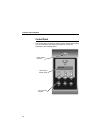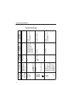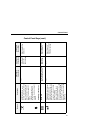
1
Quick Setup Guide
The Printronix T5000 e series of Label Printers
NOTICE
This Quick Setup Guide contains a
CD-ROM with the following materials:
• The User’s Manual
• Programmer’s Reference Manuals
• Useful utility programs
The CD-ROM is located in a plastic
pocket in the back cover.
Do not discard this guide. If you move
or pack the printer in the future, you will
need to follow the instructions in this
guide.
174951-001E
Table of Contents
Unpacking And Installing The Printer ....................................7
Unpacking The Printer ....................................................7
Removing The Internal Packing Material ........................8
Installation .......................................................................9
Controls And Indicators .........................................................9
Power Switch ..................................................................9
Control Panel ................................................................10
Loading Media And Ribbon .................................................14
Loading Roll Media .......................................................14
Loading Ribbon .............................................................19
Printing Adjustments............................................................21
Printhead Pressure Adjustment ....................................21
Printhead Pressure Block Adjustments.........................21
Positioning The Media Sensor ......................................22
Running Auto Calibrate .......................................................22
Saving The Configuration ....................................................23
Run A Barcode Demo Test..................................................24
QUICK SETUP Configuration Menu ....................................25
QUICK SETUP Submenus............................................26
For More Information ...........................................................33
5
Table of Contents
6
Unpacking And Installing The Printer
Unpacking The Printer
The printer is shipped in a carton and protective bag. Keep all
packing material in case shipping is required.
CAUTION
Avoid touching the electrical connectors to prevent
electrostatic discharge damage while setting up the printer.
The discharge of accumulated electrostatic energy can
damage or destroy the printhead or electronic components
used in this device.
CAUTION
Do not place the printer on its backside during unpacking or
handling, because damage to the printer interface connector
may occur.
7
Unpacking And Installing The Printer
Removing The Internal Packing Material
Remove the tape strips and foam pads from the printer as indicated
below. (The top lid of the shipping carton also displays these
instructions.)
A
Tape Strips (2)
B
Foam Pads (2)
C
Foam
t53unpk1
June 27, 2001
t53unpk2
June 27, 2001
Unlock
Foam Pad
8
Installation
Installation
1. Place the printer on a flat level surface that allows easy access
to all sides of the printer.
CAUTION
Never operate the printer on its side or upside down.
2. Make sure the printer power switch is in the OFF (0) position.
WARNING
Failure to properly ground the printer may result in electric
shock to the operator.
In compliance with international safety standards, this printer
has been equipped with a three-pronged power cord. Do not
use adapter plugs or remove the grounding prong from the
cable plug. If an extension cord is required, ensure that a
three-wire cable with a properly grounded plug is used.
3. Attach the AC power cord to the AC power receptacle in the
back of the printer.
CAUTION
Verify the required voltage on the printer’s model number label
on the back of the printer.
4. Attach the AC power cord to a grounded (three prong) electrical
outlet of the proper voltage.
Controls And Indicators
Power Switch
The power switch is located on the bottom back panel of the printer.
To apply power, place the switch in the | (ON) position. When you
first power on the printer, a series of initialization messages will
appear on the Liquid Crystal Display (LCD) on the control panel.
To remove power, place the power switch in the O (OFF) position.
9
Controls And Indicators
Control Panel
The control panel is located on the front of the printer and includes
an LCD, indicators, and control keys (buttons). These are
described in the following tables.
Online Status
Indicator
OFFLINE
Liquid Crystal
Display (LCD)
Job In Process
Indicator
10
Description
Indicates when the
printer is online,
offline, or when
there is a fault
condition.
A backlighted
liquid crystal
display with two
rows of 16
characters each.
Indicates when the
printer is receiving
or processing
data.
Indicator
Online Status
Liquid Crystal
Display (LCD)
Job In
Process
During a fault condition,
displays the specific
fault message and the
corrective action.
None
During a fault condition,
displays the specific
fault message and the
corrective action.
Flashes when receiving
data.
Stays lit when data has
been processed and is
waiting to be printed.
Off when no data is
being received or when
no data remains in the
buffer.
During a fault condition,
displays the specific
fault message and the
corrective action.
Flashes when receiving
data.
Stays lit when data has
been processed and is
waiting to be printed.
Off when no data is
being received or when
no data remains in the
buffer.
Displays “OFFLINE”
and a main menu,
submenu, or option.
Flashes during a fault
condition.
Displays “OFFLINE.”
Flashes during a fault
condition.
Flashes during a fault
condition.
Off.
Function in
Menu Mode
Displays “ONLINE,” the
interface type, and
emulation in use.
Off when the printer is
offline.
Function in
Offline Mode
Stays lit when the
printer is online, ready
to print, and accept
data from the host.
Function in
Online Mode
Control Panel
Status And Display Indicators
11
12
+
-
Button
INCREMENT Key in
Menu mode
TEST PRINT Key
Pressing the ↵
(ENTER) key with a
Diagnostic Test
displayed initiates the
test. Pressing ↵ again
terminates the test.
UP Key in Menu mode
FEED Key
None
Advances the
media one label
length.
None
JOB SELECT Key
DECREMENT Key in
Menu mode
Sets printer to
Offline mode.
Function in
Online Mode
PAUSE Key
Toggles the printer
between Online and
Offline modes.
Description
Scrolls through the Test
Print patterns.
Advances the media one
label length.
Displays the name and
number of the last loaded
configuration and allows
you to load the factory and/
or pre-stored printer
configurations.
Sets printer to Online mode.
Function in
Offline Mode
Scrolls right through main
menus.
Increments option values
within submenus.
Scrolls the current menu
selection one level up.
Scrolls left through main
menus.
Decrements option values
within submenus.
Sets printer to Offline mode.
Function in
Menu Mode
Controls And Indicators
Control Panel Keys
Button
Selects the
Menu mode.
None
Takes the printer Offline and
selects the Menu mode.
None
ENTER Key
Pressing the ↵ (ENTER) key in
Menu mode selects the
displayed option or value. An
asterisk then appears next to
the option or value indicating it
has been selected.
Note: If the ENTER key is
locked, “ENTER SWITCH
LOCKED” displays on the LCD
for one second. Press the
(DOWN) and ↵ (ENTER) keys
at the same time to unlock the
ENTER key.
DOWN Key in Menu mode
MENU Key
Function in
Offline Mode
Clears all data
in the printer
data buffer
when enabled.
Function in
Online Mode
None
CANCEL Key
When the CANCEL key is
enabled, pressing it will clear all
data in the printer buffer and
prevent printing of that data.
Note: The factory default =
Disable.
However, when the Coax/
Twinax Interface option is
installed, the factory default =
Enable.
Description
Selects the current
menu value and
displays an asterisk
(*) next to the value.
Scrolls between main
menu selections.
Scrolls the current
menu selection one
level down.
Function in
Menu Mode
Control Panel
Control Panel Keys (cont.)
13
Loading Media And Ribbon
Loading Media And Ribbon
Use the sample rolls of media and ribbon shipped with the printer.
CAUTION
DO NOT TOUCH the printhead or the electronic components
under the printhead assembly.
CAUTION
Do not close the pivoting deck without label stock installed
between the printhead and the platen, because debris on the
platen may damage the printhead.
Loading Roll Media
Media Cover
Liquid Crystal
Display (LCD)
PAUSE
Key
Media Hanger
Media Hanger
Guide
Pivoting
Deck
Media Width
Guide
Deck Lock
Lever
Media Damper
1. Slide the media hanger guide outward to the end of the media
hanger, and flip it down into the horizontal position (as shown).
2. Open the pivoting deck by rotating the deck lock lever fully
clockwise.
3. Slide the media width guide close to the outside end of the
media damper.
14
Loading Roll Media
Media Roll
Media Hanger
Media Hanger
Guide
4. Slide the media roll onto and towards the back of the media
hanger.
5. Place the media hanger guide under the media hanger and
against the lower part of the label core at a 45 degree angle
(as shown). This position provides the required tension for a
new label roll and the desired drag for a partial label roll.
15
Loading Media And Ribbon
Media and
Ribbon Loading
Instructions
6. Route the media as illustrated on the media and ribbon loading
instructions (or refer to the arrows on the printer frame).
16
Loading Roll Media
Media Sensor
Media
Guard
Fixed Guide
Media Sensor
Handle
Media
Width Guide
Media
Damper
7. Verify that the left edge of the media is against the fixed guide
on the bottom of the media damper.
8. Push the media width guide in until it is flush with the outer
edge of the media.
9. Check the horizontal position of the media sensor, and refer to
“Positioning The Media Sensors” on page 22.
17
Loading Media And Ribbon
Media (left edge)
Platen (left edge)
10. Align the left (inside) edge of the media with the left straight
edge of the platen (rubber drive roller).
Pivoting
Deck
Deck Lock
Lever
11. Close the printhead by pressing down on both sides of the
pivoting deck and rotating the deck lock lever fully
counterclockwise.
12. Power on the printer (place the power switch in the | position).
18
Loading Ribbon
Loading Ribbon
Empty Supply
Core
Pivoting
Deck
Ribbon
Roll
Ribbon Supply
Spindle
Deck Lock Lever
1. Install the empty supply core on the take-up spindle.
2. Slide the ribbon roll onto the ribbon supply spindle until it stops
against the spindle flange.
3. Open the pivoting deck by rotating the deck lock lever fully
clockwise until the deck swings upward.
Printhead
Media
Rear Ribbon Guide Roller
4. Thread the end of the ribbon under the rear ribbon guide roller,
then between the platen and the printhead.
19
Loading Media And Ribbon
Media Cover
Media and
Ribbon Loading
Instructions
Take-up
Core
Take-up
Spindle
5. Route the ribbon using the media and ribbon loading
instructions on the media cover (or refer to the arrows on the
printer frame).
IMPORTANT
Do not attach the ribbon to the take-up spindle without a core
installed.
6. Attach the ribbon to the fiberboard core on the ribbon take-up
spindle using the adhesive on the ribbon leader.
7. Manually rotate the spindle clockwise until the clear leader has
passed the printhead.
8. Close the pivoting deck.
20
Printhead Pressure Adjustment
Printing Adjustments
Pressure Block
Adjustment Scale
Right Pressure
Block Pointer
Lead Screw
Knob
Left
Pressure
Block
Left
Pressure
Block
Handle
Right Pressure
Block
Printhead Pressure
Adjustment Dial
Printhead Pressure Adjustment
Adjust the printhead pressure to the setting of 4.
Printhead Pressure Block Adjustments
Left Pressure Block
Manually adjust the left block so its handle is aligned with the bold
mark on the pressure block adjustment scale.
Right Pressure Block
Use the lead screw knob to position the right block with its pointer
near the right edge of the media in use.
21
Running Auto Calibrate
Positioning The Media Sensors
Media Sensor
Media Sensor
Handle(s)
Your printer is equipped with upper and lower media sensors that
detect the top-of-form position on media with label length indicators
(gaps, notches, holes, or black marks). The media sensors also
detect Paper Out conditions.
Use the handles on the lower media sensor to horizontally position
it in the center of the installed media. Slide the upper sensor directly
over the lower sensor.
Running Auto Calibrate
Due to manufacturing differences in media and ribbon, the media
sensor may have difficulty distinguishing between the label and the
liner (gap).
To ensure proper operation, you must now run Auto Calibrate:
1. Power on the printer by pressing the power switch. (For the
location of the power switch and various panel keys, refer to
“Controls And Indicators” on page 9.)
2. Press the PAUSE key until “OFFLINE” displays on the LCD.
3. Press the ↓ and ↵ keys together until “ENTER SWITCH
UNLOCKED” displays.
22
Positioning The Media Sensors
.
4. Press the ..
key; “MENU MODE/QUICK SETUP” displays.
NOTE: For a complete description of the Quick Setup menu, see
page 25.
5. Press ↑or ↓ until “Gap/Mark Sensor / Disable*” displays.
6. Press + or − until “Gap” displays.
7. Press ↵. An asterisk (*) displays next to “Gap.”
8. Press ↓ until “Auto Calibrate/Run Calibrate” displays.
9. Press ↵. Media advances until it can accurately detect the
label length indicators and then stops at the top-of-form
position. The sensed distance value then displays for one
second.
10. Auto Calibrate is successful when the sensed distance value
correctly matches that of the installed media. For the Gap
option, the sensed distance value is the physical length of one
label plus the length of one gap.
If “GAP NOT DETECTED” or “PAPER OUT” displays, check
the horizontal position of the media sensor (see “Positioning
The Media Sensors” on page 22), press PAUSE, and run Auto
Calibrate again.
11. Press the PAUSE key; “OFFLINE” displays.
12. Press the FEED key several times. Each time you press FEED,
the media should advance one label length and stop.
13. Once the sensed distance value and performance is confirmed,
save it to the desired configuration menu as described below
before powering off the printer.
Saving The Configuration
1. Make sure “OFFLINE” displays on the LCD.
.
2. Press the ..
key; “MENU MODE/QUICK SETUP” displays.
3. Press ↑or ↓ until “Save Config./1*” displays.
4. Press ↵; “Saving Configuration” displays briefly.
23
Run A Barcode Demo Test
Run A Barcode Demo Test
Before you send an actual print job, run a barcode demo test:
1. Press the PAUSE key until “OFFLINE” displays.
2. Press the TEST PRINT key until “Printer Tests/Barcode Demo”
displays.
3. Press ↵. The Barcode Demo test pattern will start and print two
barcodes.
4. Check the test pattern. If necessary, reposition the pressure
blocks to obtain a uniform print quality. In most cases, you will
need to adjust only the right pressure block.
5. If desired, you can run additional printer tests, such as Grey,
Grid, and Checkerboard. See step 1 above to start other tests.
NOTE: These tests default to run continuously. Press ↵ to end the
test.
24
Positioning The Media Sensors
QUICK SETUP Configuration Menu
QUICK SETUP
Print Intensity
-3*
-15 to 15
Print Speed
6 ips*
2-10 ips(1)
Print Mode
Transfer*
Direct
Media Handling
Tear-Off Strip*
Tear-Off
Peel-Off
Cut
Paper Feed Shift
0.00 inches* (2)
-0.50 to X inches(3)
Label Length
4 or 6 inches* (2)(4)
00.1 to 99.0 inches(5)
Label Width
4.1, 6.6, or 8.5 inches* (2)(4)
00.1 to 8.5 inches(4)
Ver Image Shift
0.00 inches* (2)
-1.00 to X inches(3)
Hor Image Shift
0.00 inches* (2)
-1.00 to 1.00 inches
Orientation
Gap/Mark Sensor
Auto Calibrate
Portrait*
Disable*
Continuous
Landscape
Mark
Inv. Portrait
Gap
Inv. Landscape
Advanced Gap
Advanced Notch
Notes:
* = Factory Default
Run Calibrate
Validator Funct.(6)
Enable*
Disable
Save Config.
1*
1-8
Power-Up Config.
Factory*
1-8
1
Maximum value depends on the width of the
printer model and printhead.
2
You can change the unit value from inches to
millimeters under Units (in MEDIA CONTROL)
See the T5000e User’s Manual for information.
3
Based on the current value setting for the Label
Length menu, up to a maximum of 12.80 inches.
4
Maximum value depends on the width of the
printer model.
5 Maximum
value depends on model width and size
of DRAM installed.
6 Appears
only if the validator option is installed.
25
QUICK SETUP Configuration Menu
QUICK SETUP Submenus
Print Intensity
Specifies the level of thermal energy from the printhead to be used
for the type of media and ribbon installed.
Large numbers imply more heat (thermal energy) to be applied for
each dot. This has a significant effect on print quality. The print
intensity and speed must match the media and ribbon type to
obtain the best possible print quality and barcode grades.
The range is -15 through +15:
•
•
In Transfer mode, the factory default is -3.
In Direct Thermal mode, the factory default is 0.
Print Speed
Specifies the speed in inches per second (ips) at which the media
passes through the printer while printing.
The range is 2 through 10 ips (in increments of 1 ips).
The factory default is 6 ips.
NOTE: The maximum print speed varies based on maximum
printer width and dot per inch (dpi) resolution of the
printhead installed (203 or 300 dpi).
Print Mode
Specifies the type of printing to be done.
•
•
Transfer. Indicates Thermal Transfer printing (ribbon installed).
Direct. Indicates Direct Thermal printing (no ribbon) and
requires special heat sensitive media.
The factory default is Transfer.
26
QUICK SETUP Submenus
Media Handling
Specifies how the printer will handle the media (labels or tag stock).
•
Tear-Off Strip. Printer prints on the media and sends it out the
front until the print buffer is empty, then positions the last label
over the tear bar for removal.
•
Tear-Off. After each label is printed, the printer positions the
label over the tear bar and waits for you to tear off the label
before printing the next one (on-demand printing). A “Remove
Label” message displays to remind you to remove the label
before the next one can be printed.
•
Peel-Off. When the optional rewinder is installed, prints and
peels die-cut labels from the liner without assistance. The
printer waits for you to remove the label before printing the next
one (on-demand printing). The label liner is rewound on the
internal rewinder. A “Remove Label” message displays to
remind you to remove the label before the next one can be
printed.
•
Cut. When the optional media cutter is installed, it
automatically cuts media after each label is printed or can cut
after a specified number of labels have been printed using a
software cut command. It cuts continuous roll paper, labels, or
tag stock.
•
Continuous. Printer prints on the media and sends it out the
front.
The factory default is Tear-Off Strip.
Paper Feed Shift
Represents the distance to advance a label (+ shift) or pull back
(– shift) when the Tear-Off Strip, Tear-Off, Peel-Off, or Cut Media
Handling option is enabled. The allowable range is -0.50 inches to
the current Label Length value setting up to a maximum of 12.80
inches in .01 inch increments.
The factory default is 0.00 inches.
27
QUICK SETUP Configuration Menu
Label Length
In most applications, the user-selected Label Length will match the
physical label length. Physical label length is the actual label length
of the media installed. Following is a list of different media types:
•
Die-cut labels – measurable length of the removable label
(leading edge to trailing edge). This does not include the
liner material or gap.
•
Tag Stock with notches or holes – measurable length from
the trailing edge of one notch or hole to the trailing edge of
the next notch or hole.
•
Tag Stock with black marks on the underside – measurable
length from the leading edge of one black mark to the
leading edge of the next black mark.
•
Continuous media (no label length indicators) –
measurable length should be within + 1-2% of the Label
Length value entered.
Label Width
The allowable range in inches is 00.1 to the maximum print width of
the printer. The allowable range in millimeters is 2.5 to the
maximum width of the printer.
Ver Image Shift
Specifies the amount to shift an image up (-) or down (+) for precise
positioning on the label. The actual height of the image is not
affected by this parameter. The allowable range is -1.00 inches to
the current Label Length value setting, up to a maximum of 12.80
inches in .01 inch increments.
The factory default value is 0.00 inches.
28
QUICK SETUP Submenus
Hor Image Shift
Specifies the amount to shift an image left (-) or right (+) for precise
positioning on the label. The actual width of the image is not
affected by this parameter. The allowable range is -1.00 through
+1.00 inches in .01 inch increments, displayed as xx/100.
The factory default value is 0.00 inches.
Orientation
Specifies the image orientation to be used when printing the label.
•
Portrait. The factory default. Portrait refers to vertical page
orientation, where the height of a page is greater than its width.
The top edge of the image is parallel to the leading edge of the
media. The following example is viewed from the front of the
printer.
4”
FEED
6”
The top edge of
the image is
parallel to the
leading edge of
the media.
Leading Edge
29
QUICK SETUP Configuration Menu
•
Inv. Portrait. Inverse Portrait refers to vertical page orientation,
where the height of a page is greater than its width. The top
edge of the image is parallel to the trailing edge of the media.
The following example is viewed from the front of the printer.
Trailing Edge
4”
The top edge of
the image is
parallel to the
trailing edge of the
media.
FEED
6”
Leading Edge
•
Landscape. Landscape refers to horizontal orientation, where
the width of a page is greater than its height. The top edge of
the image is parallel to the left edge of the media. The following
example is viewed from the front of the printer.
4”
The top edge of
the image is
parallel to the left
edge of the media.
FEED
Leading Edge
30
6”
QUICK SETUP Submenus
•
Inv. Landscape. Inverse Landscape refers to horizontal
orientation, where the width of a page is greater than its height.
The top edge of the image is parallel to the right edge of the
media. The following example is viewed from the front of the
printer.
4”
The top edge of
the image is
parallel to the right
edge of the media.
FEED
6”
Leading Edge
Gap/Mark Sensor
Specifies the sensor type needed for detecting the top-of-form
position on media with label length indicators (gaps, notches, holes,
or black marks).
•
Disable. Select when using media with no label length
indicators (no gaps, notches, holes, or black marks), or when
you want the printer to ignore all existing label length indicators
on the installed media.
NOTE: When you select Disable, the length of each label is based
on the Label Length value entered.
•
Mark. Select when using media that has horizontal black marks
located on the underside of the label liner or tag stock. The
top-of-form position is the leading edge of the black mark.
•
Gap. Select when using media with a liner space between
die-cut labels or when using tag stock with notches or holes as
label length indicators on white background media. The
top-of-form position is the leading edge of the die cut label
(trailing edge of the gap, notch, or hole).
31
QUICK SETUP Configuration Menu
•
Advanced Gap. Select when using media that has liner gaps
between die cut labels with black background. The top-of-form
position is the leading edge of the die cut label (trailing edge of
the gap, notch, or hole).
•
Advanced Notch. Select when using media with notches or
holes that interrupt a black vertical line on the underside of the
media. The top-of-form position is the leading edge of the die
cut label (trailing edge of the gap, notch, or hole).
The factory default is Disable.
Auto Calibrate
This feature is used to improve the sensitivity and reliability of the
media sensor in detecting gaps, notches, holes, or black marks on
the installed media, as well as a Paper Out condition.
To initiate Auto Calibrate, scroll to the “Auto Calibrate” menu and
press the ↵ key. The printer will advance media the distance
needed to accurately detect the label length indicators, then stop at
the top-of-form position and momentarily display the Sensed
Distance. This process will take a few seconds and will result in an
update of the printer values.
Auto Calibrate is completed successfully when the Sensed
Distance displayed correctly matches that of the installed media.
When you select Gap, the Sensed Distance should match the
length from the trailing edge of one gap to the trailing edge of the
next gap (one label + one gap). When you select Mark, the Sensed
Distance should match the length from the leading edge of one
black mark to the leading edge of the next black mark.
Auto Calibrate supports label lengths up to 24 inches.
Validator Funct.
This menu appears only if the validator option is installed.
•
32
Enable. The printer will command the validator to begin
scanning and errors will be reported. The counters will be
incremented while the validator is enabled.
QUICK SETUP Submenus
•
Disable.The printer will not command the validator to begin
scanning and no errors will be reported. The counters will not
be incremented while the validator is disabled.
NOTE: If you save a configuration with the validator enabled,
power down and power up, and the validator is not
connected or not functioning, the error message “Validator
not communicating” will display briefly. The Validator menu
will not display.
If the validator is installed, the default is Enable.
Save Config.
Allows you to save up to eight unique configurations to meet
different print job requirements. This eliminates the need to change
the parameter settings for each new job. The configurations are
stored in memory and will not be lost if you turn off the printer. The
factory default is 1.
Power-Up Config.
You can specify one the eight configurations as the power-up
configuration. The factory default is Factory.
For More Information
This Quick Setup Guide has provided general information for use of
your printer. Please refer to your User’s Manual for more detailed
information including:
•
Other Configuration Menus
•
•
•
•
•
•
Interfaces
Diagnostics and Troubleshooting
Printer Options
Specifications
Media Cutter Installation Instructions
Glossary of Terms
33
For More Information
34
PRINTRONIX
14600 MYFORD ROAD
P.O. Box 19559
IRVINE, CA 92623-9559
PHONE: 714-368-2300
FAX: 714-368-2600
CUSTOMER SOLUTIONS CENTER: 714-368-2686
PRINTRONIX
NEDERLAND BV
P.O. BOX 163, NIEUWEWEG 283
NL-6600 AD WIJCHEN
THE NETHERLANDS
PHONE: 31-24-6489489
FAX: 31-24-6489499
PRINTRONIX Schweiz GmbH
42 CHANGI SOUTH STREET 1
CHANGI SOUTH INDUSTRIAL ESTATE
SINGAPORE 486763
PHONE: 65-6542-0110
FAX: 65-6543-0220
Visit our website at:
www.printronix.com
Copyright 2002, 2003 Printronix, Inc.
174951-001E
*174951-001*