1
IBM PC I/O Scanner
(Cat. No. 6008-SI)
User Manual
Important User Information
Because of the variety of uses for the products described in this
publication, those responsible for the application and use of this control
equipment must satisfy themselves that all necessary steps have been taken
to assure that each application and use meets all performance and safety
requirements, including any applicable laws, regulations, codes and
standards.
The illustrations, charts, sample programs and layout examples shown in
this guide are intended solely for example. Since there are many variables
and requirements associated with any particular installation, Allen-Bradley
does not assume responsibility or liability (to include intellectual property
liability) for actual use based upon the examples shown in this publication.
Allen-Bradley publication SGI-1.1, “Safety Guidelines For The
Application, Installation and Maintenance of Solid State Control”
(available from your local Allen-Bradley office) describes some important
differences between solid-state equipment and electromechanical devices
that should be taken into consideration when applying products such as
those described in this publication.
Reproduction of the contents of this copyrighted publication, in whole or
in part, without written permission of Allen-Bradley Company, Inc. is
prohibited.
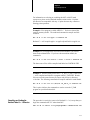
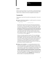
Throughout this manual we make notes to alert you to possible injury to
people or damage to equipment under specific circumstances.
WARNING: Tells readers where people may be hurt if
procedures are not followed properly.
CAUTION: Tells readers where machinery may be damaged
or economic loss can occur if procedures are not followed
properly.
Warnings and Cautions:
identify a possible trouble spot
tell what causes the trouble
give the result of improper action
tell the reader how to avoid trouble
Important: We recommend that you frequently back up your application
programs on an appropriate storage medium to avoid possible data loss.
Preface
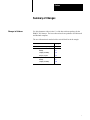
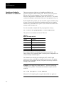
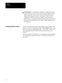
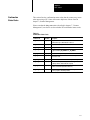
Summary of Changes
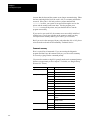
Changes to Software
Use this document with revision 1.2 of the host software package for the
IBM PC I/O Scanner. The host software has been updated to use Microsoft
and Borland compilers.
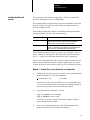
The new information is marked with a vertical black bar in the margin.
You'll find this new information:
On page:
Contents of host software package
41
Borland compiler
installing
43
compiling and linking
412
using the /d option
411
Microsoft compiler
installing
45
compiling and linking
414
i
Table of Contents
Important User Information . . . . . . . . . . . . . . . . . . . . . . . .
I
Summary of Changes . . . . . . . . . . . . . . . . . . . . . . . . . . . .
i
Changes to Software . . . . . . . . . . . . . . . . . . . . . . . . . . . . . . . . .
i
Using This Manual . . . . . . . . . . . . . . . . . . . . . . . . . . . . . . .
11
Manual's Objectives . . . . . . . . . . . . . . . . . . . . . . . . . . . . . . . . . .
Audience . . . . . . . . . . . . . . . . . . . . . . . . . . . . . . . . . . . . . . . . . .
Related Publications . . . . . . . . . . . . . . . . . . . . . . . . . . . . . . . . . .
Required Hardware . . . . . . . . . . . . . . . . . . . . . . . . . . . . . . . . . .
Required Software . . . . . . . . . . . . . . . . . . . . . . . . . . . . . . . . . . .
Source Code . . . . . . . . . . . . . . . . . . . . . . . . . . . . . . . . . . . . . . .
Conventions . . . . . . . . . . . . . . . . . . . . . . . . . . . . . . . . . . . . . . .
11
11
11
11
12
12
12
I/O Scanner Concepts . . . . . . . . . . . . . . . . . . . . . . . . . . . .
21
Chapter Objectives . . . . . . . . . . . . . . . . . . . . . . . . . . . . . . . . . . .
How Does the Scanner Relate to 1771-I/O . . . . . . . . . . . . . . . . . .
Terms . . . . . . . . . . . . . . . . . . . . . . . . . . . . . . . . . . . . . . . . . . . .
I/O Addressing . . . . . . . . . . . . . . . . . . . . . . . . . . . . . . . . . . . . . .
What the Scanner Does . . . . . . . . . . . . . . . . . . . . . . . . . . . . . . .
Operating Modes . . . . . . . . . . . . . . . . . . . . . . . . . . . . . . . . . . . .
Global RAM . . . . . . . . . . . . . . . . . . . . . . . . . . . . . . . . . . . . . . . .
Data Paths . . . . . . . . . . . . . . . . . . . . . . . . . . . . . . . . . . . . . . . .
Scanner Commands . . . . . . . . . . . . . . . . . . . . . . . . . . . . . . . . .
Host Watchdog . . . . . . . . . . . . . . . . . . . . . . . . . . . . . . . . . . . . .
Scanner Watchdog . . . . . . . . . . . . . . . . . . . . . . . . . . . . . . . . . .
21
21
23
25
26
27
27
28
29
210
210
Installation . . . . . . . . . . . . . . . . . . . . . . . . . . . . . . . . . . . . .
31
Chapter Objectives . . . . . . . . . . . . . . . . . . . . . . . . . . . . . . . . . . .
Using the Scanner with Other Products . . . . . . . . . . . . . . . . . . . .
Installation Procedure . . . . . . . . . . . . . . . . . . . . . . . . . . . . . . . . .
31
31
35
Programming Overview . . . . . . . . . . . . . . . . . . . . . . . . . . .
41
Chapter Objectives . . . . . . . . . . . . . . . . . . . . . . . . . . . . . . . . . . .
Disk Inventory . . . . . . . . . . . . . . . . . . . . . . . . . . . . . . . . . . . . . .
Installing the Borland Version . . . . . . . . . . . . . . . . . . . . . . . . . . .
Installing the Microsoft Version . . . . . . . . . . . . . . . . . . . . . . . . . .
Writing Your Program . . . . . . . . . . . . . . . . . . . . . . . . . . . . . . . . .
Compiling and Linking the Borland C++ 2.0 Version . . . . . . . . . . .
Compiling and Linking the Borland Turbo C++ 1.0 Version . . . . . . .
41
41
43
45
47
412
413
ii
Table of Contents
Compiling and Linking the Microsoft C 5.1 or 6.0 Version . . . . . . . .
Further Information . . . . . . . . . . . . . . . . . . . . . . . . . . . . . . . . . . .
414
415
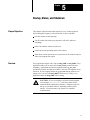
Startup, Status, and Shutdown . . . . . . . . . . . . . . . . . . . . .
51
Chapter Objectives . . . . . . . . . . . . . . . . . . . . . . . . . . . . . . . . . . .
Overview . . . . . . . . . . . . . . . . . . . . . . . . . . . . . . . . . . . . . . . . . .
Startup . . . . . . . . . . . . . . . . . . . . . . . . . . . . . . . . . . . . . . . . . . .
Host Watchdog . . . . . . . . . . . . . . . . . . . . . . . . . . . . . . . . . . . . .
Scanner Status . . . . . . . . . . . . . . . . . . . . . . . . . . . . . . . . . . . . .
Shutdown . . . . . . . . . . . . . . . . . . . . . . . . . . . . . . . . . . . . . . . . .
51
51
52
56
57
512
Discrete I/O . . . . . . . . . . . . . . . . . . . . . . . . . . . . . . . . . . . .
61
Chapter Objectives . . . . . . . . . . . . . . . . . . . . . . . . . . . . . . . . . . .
Direct Image Table Access . . . . . . . . . . . . . . . . . . . . . . . . . . . . .
Library Routines . . . . . . . . . . . . . . . . . . . . . . . . . . . . . . . . . . . .
Print or Display Image Table . . . . . . . . . . . . . . . . . . . . . . . . . . . .
Timing of Discrete I/O . . . . . . . . . . . . . . . . . . . . . . . . . . . . . . . . .
61
61
64
69
610
Scanner Management . . . . . . . . . . . . . . . . . . . . . . . . . . . .
71
Chapter Objectives . . . . . . . . . . . . . . . . . . . . . . . . . . . . . . . . . . .
Overview . . . . . . . . . . . . . . . . . . . . . . . . . . . . . . . . . . . . . . . . . .
Data Structure (Packet) . . . . . . . . . . . . . . . . . . . . . . . . . . . . . . .
Executing a Management Request . . . . . . . . . . . . . . . . . . . . . . .
Autoconfigure and Link Status Information . . . . . . . . . . . . . . . . . .
Configuration Information Byte . . . . . . . . . . . . . . . . . . . . . . . . . .
Fault and Fault Dependent Group Information Byte . . . . . . . . . . . .
Confirmation Status Codes . . . . . . . . . . . . . . . . . . . . . . . . . . . . .
Print or Display Results . . . . . . . . . . . . . . . . . . . . . . . . . . . . . . .
71
71
72
73
715
716
717
719
720
Block Transfer . . . . . . . . . . . . . . . . . . . . . . . . . . . . . . . . . .
81
Chapter Objectives . . . . . . . . . . . . . . . . . . . . . . . . . . . . . . . . . . .
Overview . . . . . . . . . . . . . . . . . . . . . . . . . . . . . . . . . . . . . . . . . .
QBT Data Structure (Packet) . . . . . . . . . . . . . . . . . . . . . . . . . . . .
Queueing a Block Transfer . . . . . . . . . . . . . . . . . . . . . . . . . . . . .
Time to Completion . . . . . . . . . . . . . . . . . . . . . . . . . . . . . . . . . .
Polling for Completion . . . . . . . . . . . . . . . . . . . . . . . . . . . . . . . . .
Confirmation Status Codes . . . . . . . . . . . . . . . . . . . . . . . . . . . . .
Print or Display Results . . . . . . . . . . . . . . . . . . . . . . . . . . . . . . .
Unsolicited Block Transfer . . . . . . . . . . . . . . . . . . . . . . . . . . . . .
Block Transfer to PLC5's in Adapter Mode . . . . . . . . . . . . . . . . . .
Block Transfer to a 1771-DCM . . . . . . . . . . . . . . . . . . . . . . . . . .
81
81
82
84
86
88
811
812
813
813
817
Table of Contents
iii
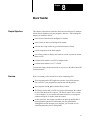
General Support Features . . . . . . . . . . . . . . . . . . . . . . . . .
91
Chapter Objectives . . . . . . . . . . . . . . . . . . . . . . . . . . . . . . . . . . .
Timing Loops . . . . . . . . . . . . . . . . . . . . . . . . . . . . . . . . . . . . . . .
Date and Time Stamp . . . . . . . . . . . . . . . . . . . . . . . . . . . . . . . . .
Command Translation . . . . . . . . . . . . . . . . . . . . . . . . . . . . . . . .
91
91
93
95
User Diagnostic Program . . . . . . . . . . . . . . . . . . . . . . . . . .
101
Chapter Objectives . . . . . . . . . . . . . . . . . . . . . . . . . . . . . . . . . . .
Starting the Program . . . . . . . . . . . . . . . . . . . . . . . . . . . . . . . . .
Program Operation . . . . . . . . . . . . . . . . . . . . . . . . . . . . . . . . . .
101
102
103
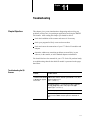
Troubleshooting . . . . . . . . . . . . . . . . . . . . . . . . . . . . . . . .
111
Chapter Objectives . . . . . . . . . . . . . . . . . . . . . . . . . . . . . . . . . . .
Troubleshooting the I/O Scanner . . . . . . . . . . . . . . . . . . . . . . . . .
111
111
Header Definitions . . . . . . . . . . . . . . . . . . . . . . . . . . . . . . .
A1
Chapter
1
Using This Manual
Manual's Objectives
This manual describes the operation and use of the IBM PC I/O Scanner
(cat. no. 6008-SI) with the supplied host software driver. After reading this
manual, you should be able to:
install the scanner board in your computer
write a program that runs on your computer to control the scanner for
your application
diagnose and correct most of the problems that might occur.
This manual begins with an introduction to I/O scanner concepts and
proceeds to detailed instructions on how to install and program your
scanner.
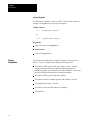
Audience
We assume that you have experience in system development and
integration and in writing software for the IBM Personal Computer family
or compatibles. We also assume that you have a working knowledge of the
C programming language, including the concepts of structures and
pointers. Prior knowledge of Allen- Bradley 1771 Series I/O products is
helpful but not essential.
Related Publications
Use this manual with its companion manual, the I/O Concepts Manual.
Refer to the manuals that accompany the 1771 Series I/O modules and
hardware you intend to use with your system.
Required Hardware
You need a computer from the IBM Personal Computer series, such as the
PC/AT or PC/XT, or a compatible such as the Allen-Bradley Industrial
Terminal T50, T60, and T35. The scanner board is installed inside the
computer.
The choice of 1771 Series I/O modules depends on your application.
A printer attached to your computer may be helpful but is not required.
1-1
Chapter 1
Using This Manual
Required Software
You need the MS–DOS operating system, version 3.0 or higher. If you’re
using the Microsoft C version of the scanner driver software, you’ll need a
Microsoft C compiler, version 5.1 or higher (version 6.0 recommended). If
you’re using the Borland C version of our software, you’ll need a Borland
C compiler, Turbo C++ 1.0 or higher (Borland C++ 2.0 recommended).
Source Code
Source code for library routines and the interrupt handler is available for a
nominal charge. To obtain source code, you must contact Order Services
and request 6008-SIDC software. They will ship you a license agreement.
Return the signed agreement. A-B source code will be supplied on
3.5-inch and 5.25-inch diskettes.
Conventions
In this manual, this type is used for special names, such as names of files
and C language identifiers.
The hexidecimal equivalent of selected error codes and commands are
given in the header definition files found in appendix A at the back of this
manual.
Numbers in this document are in decimal unless otherwise noted. Binary
numbers are marked with a trailing (binary), and hexadecimal numbers
with a trailing (hex); for example, 11010(binary) = 26 = 1A(hex).
Bits are numbered so that bit 0 is the low-order bit. For example, bit 4 is
four bits left of bit 0 and has a value of 24=16. Following C conventions,
array subscripts start at 0.
1-2
Chapter
2
I/O Scanner Concepts
Chapter Objectives
This chapter explains basic concepts and provides an overview of the
operation of the IBM PC I/O Scanner. After reading this chapter you
should understand:
how we use certain words with special meanings in this manual
how information moves between your program and the outside world
how your program can issue commands to affect operation of the
scanner
how the safety features, called watchdogs, work
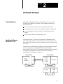
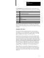
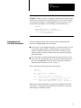
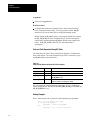
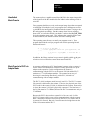
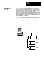
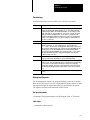
The scanner uses the 1771 Remote I/O protocol to communicate with
Allen–Bradley I/O modules. You don’t have to know the specifics of the
protocol to use the scanner with the I/O modules, but you do need to know
a few terms.
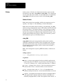
The scanner is an Allen–Bradley card that you install in the host computer
(or host). Typical hosts are the IBM PC/AT class (including the
Allen–Bradley T50, T60, and T35 Industrial Terminals and 6121 Industrial
Computer) and the IBM PC/XT class of machines (including the
Allen–Bradley 6120 Industrial Computer).
IBM PC Hardware
Host
Processor
(i.e. 80286)
1771-I/O Hardware
6008-SI
How Does the Scanner
Relate to 1771-I/O
IBM PC
1771-I/O Protocol
1771-AS
or
1771-ASB
or
1771-DCM
Universal I/O
1771-I/O Bus
1771-JAB
Single
Point
I/O
2-1
Chapter 2
I/O Scanner Concepts
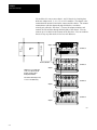
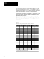
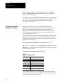
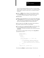
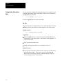
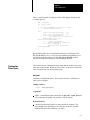
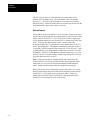
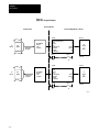
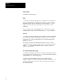
I/O modules sit in one or more chassis. An I/O chassis is a housing that
holds one adapter and 1, 2, 4, 8, 12, or 16 I/O modules. The adapter is the
communication interface between the scanner and the chassis. The scanner
communicates with the adapter through shielded two–conductor
twisted–pair cable (the “blue hose”). In turn, the adapter monitors and
controls the I/O modules through the backplane of the chassis. You can
connect up to 16 chassis to the scanner on the blue hose. You can combine
chassis in any way that results in 8 or less rack addresses.
Industry
Bus
SI Scanner
Host
Processor
Adapter
I/O Chassis
Remote I/O Cable
I/O Chassis
Adapter
I/O Chassies can contain 8 bit,
16-bit, or 32-bit discrete I/O
modules. Analog, and/or
intelligent I/O modules.
You address them using 1/2 slot,
1-slot or 2-slot addressing
I/O Chassis
Adapter
I/O Chassis
Adapter
14652
2-2
Chapter 2
I/O Scanner Concepts
We can divide I/O, and therefore I/O modules, into discrete and intelligent
modules.
Discrete I/O is characterized by one terminal (or point) per I/O image table
bit. Your program handles discrete I/O through I/O image tables, where
each input or output terminal corresponds to one of the 1024 input and
1024 output image table bits (64 x 16 bits = 1024 bits.)
The input image table is an area of memory that monitors the terminals of
discrete input modules. When an input switch is closed, the corresponding
bit is set (1). The output image table is an area of memory that controls
output terminals of output modules. After a bit is set to 1, the
corresponding switch is closed or the terminal is energized.
A standard–density module is a discrete input or output module that has 4,
6, or typically 8 input or output terminals. A high–density module is a
discrete input or output module that has 16 input or output terminals. A
quad–density module is a discrete input or output module that has 32 input
or output terminals.
Intelligent I/O is characterized by the transmission of one or more 16–bit
words in a particular format to or from an I/O module. A block transfer
(BT) is the transmission of data to or from an intelligent I/O module. A
BT read or read BT transfers information (typically analog input and status
data) from the module to the host; a BT write or write BT transfers data
(typically analog output and configuration data) from the host to the
module.
Terms
You should become familiar with these terms used to describe the I/O
subsystem.
Input image table: An area of memory that monitors input terminals of
input modules. When an input switch is closed, its corresponding input bit
is set. 64 16–bit words (1024 points) are available.
Output image table: An area of memory that controls output switches of
output modules. When a bit is set, its corresponding output is energized.
64 16–bit words (1024 points) are available.
Discrete I/O: I/O characterized by one terminal per image table bit
(terminal and point are the same).
Standard density module: Discrete I/O module having four, six, or
typically eight input or output points.
High density module: Discrete I/O module having 16 input or output
points.
2-3
Chapter 2
I/O Scanner Concepts
Quad density module: Discrete I/O module having 32 input or output
points.
I/O chassis: One of four different housings sized to hold either four, eight,
twelve, or sixteen discrete I/O modules.
Slot: Position in an I/O chassis the width of one discrete I/O module.
I/O group: An addressing concept representing 16 input bits (one input
image table word) and 16 output bits (one output image table word).
In hardware, an I/O group can represent one or two slots in an I/O chassis.
It has an address number.
Half–slot addressing: Addressing where an I/O group represents a half of
a slot.
One–slot addressing: Addressing where an I/O group represents one slot.
Two–slot addressing: Addressing where an I/O group represents two
slots.
I/O rack number: An addressing concept representing 8 I/O groups. An
I/O rack number can be distributed over one, two, three, or four I/O
chassis; or two rack numbers can be assigned to one I/O chassis, depending
on chassis size and your application requirements.
Module address: An address that defines the physical location of the
module in the I/O chassis by its I/O rack number and starting slot number.
I/O update: The scanner’s serial scan of all I/O chassis in the I/O
subsystem. This scan is asynchronous to scans between the scanner and
host processor.
Scan list: A list specifying the order in which I/O adapters are to be
scanned. It is specified by the host and sent to the scanner module as a
scanner management command. Although a maximum of 16 I/O adapters
is allowed, the scan list can specify a maximum of 64 I/O adapters. This is
done to allow the scanner to scan adapters more than once during its scan
cycle if more frequent updates are desired.
Block transfer: The transfer of data to or from an intelligent I/O module
up to 64 words at a time.
Scanner management request: A command from the host to the scanner
used to control and configure the scanner board.
2-4
Chapter 2
I/O Scanner Concepts
Fault dependent group: A group of I/O adapters treated as a single entity
for the purposes of fault detection. If one of the defined group faults all in
the group are in fault.
I/O Addressing
You assign each adapter an I/O rack number (0 to 7) by setting switches on
the adapter. A rack may be single chassis; or two to four chassis may be
comprised in one rack number; or a single chassis can be addressed as two
racks. It is not necessary to assign rack numbers sequentially: for instance,
you could have a full rack 0, half a rack in rack 3, and a quarter rack in
groups 6–7 of rack 7.
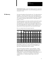
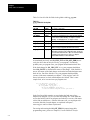
For addressing purposes, each rack is equivalent to a block of 8 I/O groups
in the I/O image table. Groups within a rack are numbered from 0 to 7.
An I/O group is two 16–bit words, one from the output image table and
one from the input image table, with the same address. (Please refer to the
I/O Concepts Manual for more information.) In most applications, only
the input word or only the output word is used in any given I/O group.
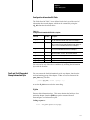
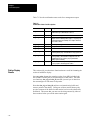
Here is an example layout of the output image table:
Group
word #
(hex)
rack
0
1
2
3
4
5
6
7
00-07
0
xxxx
xxxx
xxxx
xxxx
xxxx
xxxx
xxxx
xxxx
08-0F
1
xxxx
xxxx
xxxx
xxxx
xxxx
xxxx
xxxx
xxxx
10-17
2
xxxx
xxxx
xxxx
xxxx
xxxx
xxxx
xxxx
xxxx
18-1F
3
xxxx
xxxx
xxxx
xxxx
xxxx
xxxx
xxxx
xxxx
20-27
4
xxxx
xxxx
xxxx
xxxx
xxxx
xxxx
xxxx
xxxx
28-2F
5
xxxx
xxxx
xxxx
xxxx
xxxx
xxxx
xxxx
xxxx
30-37
6
xxxx
xxxx
xxxx
xxxx
xxxx
xxxx
xxxx
xxxx
38-3F
7
xxxx
xxxx
xxxx
xxxx
xxxx
xxxx
xxxx
xxxx
The word numbers above can be used as subscripts. (We’ll look closely at
that in chapter 6, Discrete I/O.) Each 16–bit word corresponds to 16
discrete I/O terminal positions, terminal 17 octal (15 decimal) to the
high–order bit and terminal 00 to the low–order bit.
Just as each I/O group has an address, so does each adapter. Adapter
addresses are used in the scan list (see, What the Scanner Does, below).
The adapter address is the address of the first I/O group covered by the
adapter, divided by 2. This is numerically the same as (rack x 4) +
(starting group / 2), where the rack and group are both numbered from 0 to
7 as shown above. If you prefer, you can think of 1/4 racks being
numbered from 0 to 3, and then the adapter address is (rack x 4) +
(quarter).
2-5
Chapter 2
I/O Scanner Concepts
A slot is a position in an I/O chassis for one I/O module. In one–slot or
single–slot addressing, an I/O group represents a single slot. In two–slot or
double–slot addressing, an I/O group represents two slots.
What the Scanner Does
The scanner runs asynchronously in relation to the host. When either one
wants to get the other’s attention, it must issue a hardware interrupt.
Information is passed through a global RAM. Both the host and the
scanner have the ability to postpone servicing an interrupt if in the middle
of another interrupt–driven task.
The scanner maintains a scan list, which is a list of adapters to be serviced
by the scanner. A given adapter may appear once, several times, or not at
all in the scan list. (The scan list is empty until you perform
AUTOCONFIGURE at which point AUTOCONFIGURE puts every
adapter in the list once.) The scan list starts as simply the list of adapters,
each occurring once, but your program can issue a scanner command to
alter the scan list.)
An exchange (or an adapter scan) is the scanner’s interchange of
information with one adapter. During an exchange, the scanner may
receive data or status information from the adapter or send data or
commands to the adapter, or both. Both block transfers and discrete I/O
transfers can be done during the same exchange if the adapter’s chassis
contains both kinds of I/O modules.
After servicing each adapter, the scanner looks at its command queue to
see if any commands are waiting. If so, and if the current operating mode
allows, the scanner executes one command. If the scanner has a
confirmation of this command or of a previously executed command, it
puts the confirmation in the global RAM and interrupts the host.
The scan list is circular: each time the scanner reaches the end of the scan
list it starts again at the beginning. An I/O scan (sometimes called just a
scan) is one complete cycle by the scanner through the scan list, from any
point to the same point.
Every time the host interrupts the scanner, the scanner puts a marker in the
scan list at the point of the adapter most recently scanned. If the scanner
works its way through the scan list to the same point without receiving an
interrupt from the host, the scanner interrupts the host. (If the scan list
contains no adapters, the scanner waits for 5 ms before interrupting the
host.)
2-6
Chapter 2
I/O Scanner Concepts
Thus you can be certain that the I/O image tables are refreshed once per
scan list. Partial refreshes take place more frequently if your program
executes a lot of block transfers or management requests: whenever the
global ram is transferred the I/O image tables are refreshed as far as the
scanner has got in the scan list since the last interrupt. Your program can
also force a partial refresh: see the update function in chapter 6, Discrete
I/O.
Operating Modes
The scanner has three modes of operation: program, test, and run modes.
Discrete inputs are read in all three modes.
In program mode no discrete outputs are sent to the adapters, and the
adapters are instructed to hold all discrete outputs reset (zero). The
scanner holds any block transfer requests in its queue without servicing
them.
In test mode the adapters are still instructed to hold discrete outputs
reset, but the scanner sends discrete information to them. Block
transfers can proceed in test mode, but their outputs will be held reset.
In run mode discrete output information is sent to the adapters, and the
adapters are permitted to update the output modules. Block transfers
may be performed.
When your program first starts up scanner operation, the scanner is in
program mode. Your program must issue a command to change to run
mode.
Global RAM
The scanner has a 2048–byte area of RAM that we call a global RAM,
shared by both the IBM PC and the scanner. This is not a true global
RAM, because the host and the scanner can’t access it at the same time.
Instead, the host and the scanner exchange control of the global RAM by
means of interrupts. When the scanner interrupts the host, the scanner is
turning over control of the global RAM to the host. When the host
interrupts the scanner, either the host has the global RAM and wants to
return it or the host doesn’t have the global RAM but wants access to it.
Access to the global RAM is ultimately controlled by hardware and by
scanner firmware. For the host side, we supply an interrupt handler or
interrupt service routine that is automatically invoked whenever the
scanner interrupts the host. Our interrupt service routine copies
information as needed between your program’s data area and the global
RAM.
2-7
Chapter 2
I/O Scanner Concepts
Because our interrupt handler takes care of all details of the global RAM,
you don’t have to be concerned with the bits and bytes. You should know
that the global RAM contains two kinds of information:
the I/O image tables are comprised of an output image image table and
an input image table. Every time control of the global RAM is
transferred, the interrupt routine copies new inputs to your program’s
data area from the global RAM and new outputs from your program’s
data area to the global RAM.
a mailbox area is where the host can send commands to the scanner and
the scanner sends back confirmations and data. A list of commands is
given later in this chapter.
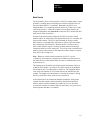
Data Paths
Here is the path followed by a discrete input bit:
An external device causes an input of a discrete input module to turn
“on.”
When next asked by the adapter, the input module reports the new input
information. The adapter updates its internal input image table by
setting the bit corresponding to the particular input point.
When next scanned by the scanner, the adapter reports the new input
information. The scanner updates the input image table in the global
RAM by setting the bit corresponding to the particular input point.
The host interrupt handler reads the input image information in the
global RAM and copies it to a duplicate input image table available to
your program. Your program now knows that an input on a particular
input module is “on.”
The path of an output bit is essentially the reverse of the input path:
Your program sets a bit in its output image table. Your program knows
that this bit maps to an output on a particular output module.
The scanner interrupts the host, the interrupt handler copies your
program’s output image for that rack to the global RAM.
When the scanner next scans the adapter controlling the particular
output module, it tells the adapter to update its output image table with
the new information.
The adapter tells the discrete output module to update its outputs with
the new information.
2-8
Chapter 2
I/O Scanner Concepts
The discrete output module turns on the output. Any external device
attached to the output module then activates.
For timing information, please see Timing of Discrete I/O in chapter 6,
Discrete I/O.
Scanner Commands
There are two types of scanner commands, block transfers and
management requests. There are two block transfer commands (BT
commands):
block transfer read
block transfer write
A management request affects the operation of the scanner itself. There
are six management requests:
set mode changes the scanner’s operating mode to program, test, or run
mode
autoconfigure goes on the link to see what devices are attached
scan list changes the order in which adapters are scanned, and their
relative frequency
link status asks the scanner to report all information it has about the
adapters that are connected
setup changes the baud rate and connects or disconnects the line
termination resistor
fault dependent group designates one or more groups of adapters such
that, if one adapter in a group is faulted, the scanner instructs the others
to be faulted also
The control/status and general data areas are used to transfer scanner
management commands to the scanner and provide status information to
the host. In addition, this area of the global RAM is used for block
transfers between the host and intelligent I/O devices in the I/O system.
2-9
Chapter 2
I/O Scanner Concepts
Host Watchdog
Suppose that your program crashes, either because of logic errors or
because of operator intervention. Or suppose that through logic errors
your program gets into an infinite loop. In these cases the program is no
longer sending meaningful information to the scanner through the interrupt
handler. There is no way for the interrupt service routine (ISR) to
recognize all possible host program failures reliably, so instead a “host
watchdog’’ scheme has been implemented.
In essence, your program must take a particular action every so often (by
default, every second). If the ISR recognizes that the required action has
not been taken recently enough, the ISR infers that your program has failed
and simply stops talking to the scanner. The scanner in turn recognizes this
as a host failure and goes off the link within 50 ms; all the adapters go
inactive and output terminals go to last state or reset as determined by
switches you set on the chassis.
We’ll tell you about the necessary programming steps in chapter 5, Startup,
Status, and Shutdown.
Scanner Watchdog
If the host computer doesn’t respond to an interrupt from the scanner
within 100 ms or less, the scanner assumes that the host hardware and
BIOS is no longer active. In this case the scanner goes off the link, and 50
ms later the adapters set the output modules in last state or reset according
to your switch settings. The scanner then goes into its power–up sequence,
waiting for new startup commands from the host.
This scanner watchdog feature lets you end one program run and start
another without cycling host power. Even if your program locks up the
host computer, if you are able to do a soft reset (Ctrl–Alt–Del) the scanner
is ready and waiting for your program. More importantly, if your program
fails or is interrupted, even by a reboot of the computer, all discrete outputs
are in last state or reset, according to the switches you set on the adapters.
2-10
Chapter
3
Installation
Chapter Objectives
This chapter explains how to install the IBM PC I/O Scanner. After
reading this chapter you should be able to:
determine whether you already have hardware or software products
installed that would conflict with the scanner
configure the scanner board for a suitable address in your host’s RAM
install the scanner board in the host
connect the 1771 Series I/O cable to the scanner.
In this manual, we do not explain how to cable and configure 1771 Series
I/O products. For that information, please refer to the manuals that came
with those products.
Using the Scanner
with Other Products
You need to be aware of possible hardware or software conflicts between
other products and the scanner. In this section we point out the hardware
and software features in the scanner that might lead to conflict with other
products, and where possible we tell you how to avoid those conflicts.
However, there are so many add-ons available that we cannot guarantee
that the scanner works with any particular one.
Hardware Interrupt
On the system board, the scanner can use interrupt request lines IRQ3,
IRQ5, IRQ10, and IRQ12. These interrupt request lines are selected by
positioning the jumper located on the scanner board. Results are
unpredictable if any other devices use these lines. In particular, you can’t
have two IBM I/O scanners operating in the same host, since the host
software cannot direct Allen-Bradley I/O calls to a particular scanner
board.
Allen-Bradley products that use the IRQ3 include the 1784-KTP and the
6121-CBB ‘combo’ card (used with the 6120 and 6121 Industrial
Computers).
3-1
Chapter 3
Installation
IBM’s Technical Reference Manuals show line IRQ3 used by the
secondary serial port (COM2 device). If you have 2 serial ports active on
your host computer and you have selected IRQ3, you must disable COM2
before installing the scanner board. (Many multi-junction cards have
jumpers to disable this port; see your manufacturer’s documentation for
details.)
CAUTION: If you have other cards that use the interrupt line
you have selected, (IRQ3, IRQ5, IRQ10, or IRQ12), physically
disconnect them to avoid damaging the 6008-SI or other cards.
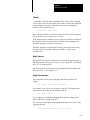
To change the interrupt request line setting, complete these steps:
1.
Remove the cover from the computer that contains the I/O scanner.
2.
Remove the I/O scanner from the computer.
3.
Remove the four screws securing the daughterboard to the main
board. Unplug and remove the daughterboard.
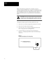
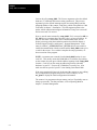
4.
Locate the double row of stake pins on the main board (see
Figure 3.1). A jumper plug connects 2 pins to select the interrupt
request line.
Figure 3.1
Location of Interrupt Request Line Jumper Plug
Note: Interrupt line designations are
not actually shown on the board.
1 1
2 0 3 5
Default setting
IRQ3
3-2
Chapter 3
Installation
5.
To change the setting, pull the jumper off the pins and reposition it on
the pins for the interrupt line you desire. See Table 3.A for interrupt
request line definitions.
Table 3.A
Interrupt Request Line Definitions
6.
Interrupt Line:
Explanation:
IRQ3
Default setting. Conflicts with COM2 port on machines so equipped.
Conflicts with the KTP card.
IRQ5
This setting conflicts with the hard disk controller when the card is
used in an IBMXT or AT clone. This setting would also conflict with
the LPT2 port on machine so equipped.
IRQ10
Not available on IBMXT. Not assigned on 1784T50 or IBMAT, but
may conflict with 3rd party boards.
IRQ12
Not available on IBMXT. Not assigned on 1784T50 or IBMAT, but
may conflict with 3rd party boards.
Write your application software to use the newly selected interrupt
request line setting.
Software Interrupt
The host receives interrupts from the scanner through the selected line
(IRQ3, IRQ5, IRQ10, or IRQ12). Table 3.B lists the software interrupt
vectors.
Table 3.B
Software Interrupt Vectors
Interrupt Line:
Software Interrupt Vector:
IRQ3
0Bh
IRQ5
0Dh
IRQ10
072h
IRQ12
074h
Results are unpredictable if you have any other hardware that uses
interrupt IRQ3, IRQ5, IRQ10, or IRQ12 (It is likely that the other software
simply ceases functioning while your scanner 0 interface program is
running, but we cannot guarantee that this is the only result).
The scanner driver routines also use the timer follow–on interrupt, number
1Ch. After its own processing, the scanner code will call any previously
set follow–ons to interrupt 1Ch. If the other software is taking too great a
portion of system resources, your scanner application program may not
operate correctly.
3-3
Chapter 3
Installation
Despite IBM recommendations to the contrary, some resident software
uses the system timer hardware interrupt, number 8, rather than the
follow-on described in the preceding paragraph. The scanner may work
erratically or may fail to work at all if such programs are active when a
scanner program is started.
I/O Ports
The scanner does not use any I/O ports.
RAM Address
DIP switches on the scanner board let you configure it to any starting
address in RAM, from 0400(hex) to FC00(hex), in increments of
4000(hex) = 16 K bytes. (The scanner cannot be configured to operate in
extended or expanded memory.) The scanner board occupies 1801(hex)
(6K+1) bytes beginning at the address you select. You are responsible for
selecting an address that starts at a free 6K+1 byte range.
The documentation for each of your add-on boards should tell you which
addresses (if any) it uses in system RAM. In addition, we can tell you
about the following common memory uses:
monochrome display memory: B000(hex)-B7FF(hex)
color/graphics display memory: B800(hex)-BFFF(hex)
Enhanced Graphics Adapter memory: C000(hex)-C3FF(hex) for the
BIOS, plus an area that could be as large as A000(hex)-BFFF(hex),
depending on the display mode
hard disk BIOS (on the PC XT, not the PC AT):
C800(hex)-CBFF(hex) for the first controller, CC00(hex)-CFFF(hex)
for the second controller if a second one is installed
cartridge ROM reserved area: E000(hex)-EFFF(hex) on some systems
ROM BIOS: F000(hex)-FFFF(hex)
Use the above information, and documentation from the manufacturers of
your add-on boards, to select an area of memory that is available for the
scanner. During the installation process you’ll set switches according to
the memory area you select.
3-4
Chapter 3
Installation
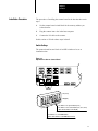
Installation Procedure
The procedure of installing the scanner board in the host has three main
steps:
1.
Set the scanner board switch block for the memory address you
selected earlier.
2.
Plug the scanner into a slot in the host computer.
3.
Connect the I/O cable to the scanner.
In this section we’ll look at those steps in detail.
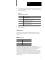
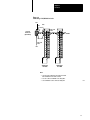
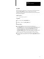
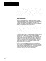
Switch Settings
The scanner board has one block of ten DIP switches to be set at
installation time.
Figure 3.2
Dip Switch Location on Scanner Board
Switches
on (Close)
off (Open)
Set switches 710 open for PC/XT (6120)
Set switches 710 closed for PC/AT (T50, 6121, 6122)
(photo shows switches set for PC/AT)
Set switches 1-6 set for RAM address.
(photo shows switches set for RAM address C4000)
3-5
Chapter 3
Installation
The factory sets the switches for memory address C000(hex) for an IBM
PC AT or other machine with a 16-bit bus. If you’re running on a PC XT
or another 8-bit bus machine, or if you want to configure the scanner at an
address other than C000(hex), you’ll have to change the switches.
First set switches 7 through 10 to all closed for a PC AT or similar, all open
for a PC XT or similar. The factory setting is all closed, for a PC AT or
other machine with a 16-bit bus.
Next set switches 1 through 6 for the memory address you selected.
Table 3.C shows the correct setting of switches 1 through 6, in that order,
for every hex address below F000, where O is an open switch and c is a
closed switch:
Table 3.C
Dip Switch Settings for Memory Address (Switches 1 through 6)
Hex
Address
Switch
Setting
Hex
Address
Switch
Setting
Hex
Address
Switch
Setting
0400
Occ ccc
5000
ccO cOc
A000
ccc OcO
0800
cOc ccc
5400
OcO cOc
A400
Occ OcO
0C00
OOc ccc
5800
cOO cOc
A800
cOc OcO
1000
ccO ccc
5C00
OOO cOc
AC00
OOc OcO
1400
OcO ccc
6000
ccc OOc
B000
ccO OcO
1800
cOO ccc
6400
Occ OOc
B400
OcO OcO
1C00
OOO ccc
6800
cOc OOc
B800
cOO OcO
2000
ccc Occ
6C00
OOc OOc
BC00
OOO OcO
2400
Occ Occ
7000
ccO OOc
C000
ccc cOO
2800
cOc Occ
7400
OcO OOc
C400
Occ cOO
cOc cOO
2C00
OOc Occ
7800
cOO OOc
C8001
3000
ccO Occ
7C00
OOO OOc
CC00
OOc cOO
3400
OcO Occ
8000
ccc ccO
D000
ccO cOO
3800
cOO Occ
8400
Occ ccO
D400
OcO cOO
3C00
OOO Occ
8800
cOc ccO
D8002
cOO cOO
4000
ccc cOc
8C00
OOc ccO
DC00
OOO cOO
4400
Occ cOc
9000
ccO ccO
E000
ccc OOO
4800
cOc cOc
9400
OcO ccO
E400
Occ OOO
4C00
OOc cOc
9800
cOO ccO
E800
cOc OOO
9C00
OOO ccO
EC00
OOc OOO
1 Not available for the IBM PC XT
2 Recommended for IBM PC AT computers with EGA and VGA graphics
3-6
Chapter 3
Installation
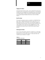
Plugging in the Board
The scanner board requires two slots. (Any two adjacent slots will do: the
board doesn’t have to be plugged into any particular slot.) The Installation
and Setup manual from IBM, or the corresponding manual from the maker
of your host computer, explains in detail how to install any add-on board.
(See the Internal Option Installation Instructions section in the IBM
manual.)
Host Bus Speed
The scanner is designed to operate on a standard 6 to 8 Mhz IBM AT bus.
Newer 386 PC compatibles operate their busses at faster rates (11 or 12
Mhz) with no wait states. The scanner will not synchronize properly at
these higher rates and will return a 102 error code at the completion of the
setup command. Most of the faster 386 PC compatibles have a setup
screen that allows you to choose the standard IBM AT bus speed. The
standard bus speed must be chosen in order for the scanner to operate
properly.
Attaching the I/O Cable
The 1771 Series I/O cable (the “blue hose”) terminates in a 15-pin female
D-shell connector, and the scanner has a 15-pin male connector accessible
through the rear cover of the host computer. Connect the cable to the
scanner and your installation is complete.
Table 3.D
1771 I/O Cable Connections
Scanner:
Cable:
Adapter:
pin 8
blue
terminal 1
pin 7
shield
terminal 2
pin 6
clear
terminal 3
3-7
Chapter 3
Installation
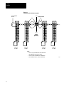
Figure 3.3
Connecting 1771 I/O Cable in Parallel
Line Termination
Resistor
Pin 8
Twinaxial Cable
Blue
Blue
Shield
Shield
1
1
1
1
2
2
2
2
3
3
3
3
4
4
4
4
5
5
5
5
6
6
6
6
7
7
7
7
8
8
8
8
White
White
Pin 1
D-shell
Connector
(back view)
9
9
9
9
10
10
10
10
11
11
11
11
12
12
12
12
Swingarm
1771WB
Swingarm
1771WB
Swingarm
1771WB
Swingarm
1771WB
Note:
• Use the setup command to disconnect the shunt
line termination resistor in the scanner.
• You can connect a maximum of 16 swingarms.
• Use termination resistor on the last swingarm.
3-8
14864
Chapter 3
Installation
Figure 3.4
Connecting 1771 I/O Cable in Series
Pin 1
Blue
White
Shield
D-shell
Connector
(back view)
Twinaxial
Cable
Blue White
Twinaxial
Cable
Pin 8
Swing-Arm
1771-WB
Swing-Arm
1771-WB
Note:
• Use the setup command to disconnect the shunt
line termination resistor in the scanner.
• You can connect a maximum of 16 swingarms.
• Use termination resistor on the last swingarm.
14865
3-9
Chapter
4
Programming Overview
Chapter Objectives
This chapter gives you a general overview of the programming process.
After reading this chapter you should be able to:
identify the purpose of every file on your distribution disk
install the software on your hard disk (if you have one)
recognize the special features of source code for a program that
interfaces with the scanner
select names for your variables that won’t conflict with the names in the
programs we supply
select the necessary options to compile and link a scanner interface
program.
Disk Inventory
The host software is shipped on a single 720K (3.5”) diskette, for use with
Borland and Microsoft compilers. The disk contains an include file
required with all your programs; run–time libraries in the small, compact,
medium, large, and huge memory models; and source and executable code
for the diagnostic program described in chapter 10, User Diagnostic
Program.
The host software package also includes two 360K 5.25-inch diskettes, one
for use with Borland compilers and the other for use with Microsoft
compilers. The combined contents of these two diskettes is identical to the
contents of the 720K diskette.
Table 4.A lists the contents of the host software package.
Table 4.A
Contents of Host Software Package
File:
Contents:
H_6008SI.H
include file
6008SI?M.LIB
run-time libraries compiled with Microsoft C 6.0A
6008SI?B.LIB
run-time libraries compiled with Borland C++ 2.0
U_D1M.EXE
user diagnostic program (Microsoft C version)
U_D1B.EXE
user diagnostic program (Borland C version)
4-1
Chapter 4
Programming Overview
Table 4.B lists the rest of the files that make up the source code for the user
diagnostic program:
Table 4.B
Source Code for the User Diagnostic Program
File:
Contents:
U_D1.C
main program
U_D1.H
include file for the U_*.C files
U_BT.C
single block transfers
U_BTC.C
continuous block transfers
U_BTM.C
multiple block transfers
U_DISC.C
fullscreen discrete I/O
U_GET.C
keyboard handler
U_GROUP.C
singlegroup discrete I/O
U_MR.C
management requests
U_PICK.C
main menu
We provide the diagnostic program source files so that you have extended
examples of successful programming for the scanner. You should feel free
to experiment by modifying them, though we cannot support any modified
program versions.
Important: All of the files on the diskettes are Copyright
(C)Allen-Bradley Company and may not be distributed or copied (other
than from the distribution disk to your hard-disk or working diskette)
without our permission.
All of the source files are identical between the two diskettes. The
run-time libraries are different and have different names, as explained
below. The executable programs work the same, but contain different code
because they were compiled with different compilers.
If your system is equipped with a hard disk, please read the installation
hints for the Borland or Microsoft version, below. (We provide hints rather
than firm instructions because your hard disk could be organized in many
ways for system development.)
If your system doesn’t have a hard disk, you can write and run scanner
programs using just floppy drives. Please consult your compiler and linker
manuals for instructions on organizing your floppy disks.
4-2
Chapter 4
Programming Overview
Installing the Borland Version
This section provides installation suggestions. Feel free to modify this
procedure according to your own configuration.
Important: We recommend that you make backup copies of the
distribution disks and keep the originals in a safe place, away from your
computer and away from stray magnetic fields.
Please make sure that your compiler is installed according to Borland’s
instructions before you follow the procedure below.
If you have a:
Then:
3.5inch floppydisk drive
Write protect the supplied 720K diskette (or your backup copy) by
sliding the write-protect tab so that a hole shows through the
diskette casing. Insert the diskette in the floppydisk drive.
5.25inch floppydisk drive
Write protect the supplied 360K diskette labeled `Borland C version'
(or your backup copy) by applying a standard adhesive foil
write-protect tab. Insert the diskette in the floppydisk drive.
In the command examples below, we assume you’re using the a: drive, so
please substitute b: if appropriate. We also assume that your hard disk is
drive c: –– again, please substitute another drive letter if appropriate.
There are two main approaches: either copy the scanner’s include file and
libraries into the directories with the compiler–supplied files, or copy the
scanner files into the work directory where you’ll be developing software.
Method 1: Scanner files in same directories as compiler files
1.
Change to the root directory for the compiler. If you used Borland’s
default installation, the command will be one of the following:
for Borland C++ 2.0:
cd \borlandc
for Turbo C++ 1.0:
cd \tc
The command will be different if you performed an installation to a
directory other than Borland’s default.
2.
Copy the header file and libraries, like this:
copy a:h_6008si.h c:include
copy a:6008si?b.lib c:lib
You’ll see five libraries copied, for the small, compact, medium,
large, and huge memory models.
3.
Create your development directory using the md command, and
change to that directory by using the cd command.
4-3
Chapter 4
Programming Overview
4.
Create an EXAMPLES directory under your development directory,
using this command:
md examples
5.
Copy the user diagnostic program (source code and executable) to
this directory by typing the commands
copy a:u*.? c:examples
copy a:u_d1b.exe c:examples\u_d1.exe
If you wish, you can print the source files (approximately 35 pages)
by using this command:
print examples\u_*.?
Method 2: Scanner files in development directory
1.
Create your development directory using the md command, and
change to that directory by using the cd command.
2.
Copy the header file and libraries, like this:
copy
copy
a:h_6008si.h c:
a:6008si?b.lib c:
You’ll see five libraries copied, for the small, compact, medium,
large, and huge memory models.
3.
Create an EXAMPLES directory under your development directory,
using this command:
md examples
4.
Copy the user diagnostic program, source code and executable, to this
directory by typing these commands:
copy a:u*.? c:examples
copy a:u_d1b.exe c:examples\u_d1.exe
If you wish, you can print the source files (approximately 35 pages)
by using this command:
print examples\u_*.?
4-4
Chapter 4
Programming Overview
Installing the Microsoft
Version
This section provides installation suggestions. Feel free to modify this
procedure according to your own configuration.
We recommend that you make backup copies of the distribution disks and
keep the originals in a safe place, away from your computer and away
from stray magnetic fields.
Please make sure that your compiler is installed according to Microsoft’s
instructions before you follow the procedure below.
If you have a:
Then:
3.5inch floppydisk drive
Write protect the supplied 720K diskette (or your backup copy) by
sliding the write-protect tab so that a hole shows through the
diskette casing. Insert the diskette in your diskette drive.
5.25inch floppydisk drive
Write protect the supplied 360K diskette labeled `Microsoft C
version' (or your backup copy) by applying a standard adhesive foil
write-protect tab. Insert the diskette in your diskette drive.
In the command examples below, we assume you’re using the a: drive, so
please substitute b: if appropriate. We also assume that your hard disk is
drive c: –– again, please substitute another drive letter if appropriate.
There are two main approaches: either copy the scanner’s include file and
libraries into the directories with the compiler–supplied files, or copy the
scanner files into the work directory where you’ll be developing software.
Method 1: Scanner files in same directories as compiler files
1.
Change to the root directory for the compiler. If you used Microsoft’s
default installation of C 6.00, the command is:
for Microsoft C 6.0:
cd \c600
If you have an earlier version of Microsoft C, or installed Microsoft
C 6.0 to a non–default directory, the proper cd command depends on
the directory you chose when you installed the compiler.
2.
Copy the header file and libraries, like this:
copy a:h_6008si.h c:include
copy a:6008si?m.lib c:lib
You’ll see five libraries copied, for the small, compact, medium,
large, and huge memory models.
3.
Create your development directory using the md command, and
change to that directory by using the cd command.
4-5
Chapter 4
Programming Overview
4.
Create an EXAMPLES directory under your development directory,
using this command:
md examples
5.
Copy the user diagnostic program (source code and executable) to
this directory by typing these commands:
copy a:u*.? c:examples
copy a:u_d1m.exe c:examples\u_d1.exe
If you wish, you can print the source files (approximately 35 pages)
by using this command:
print examples\u_*.?
Method 2: Scanner files in development directory
1.
Create your development directory using the md command, and
change to that directory by using the cd command.
2.
Copy the header file and libraries, like this:
copy a:h_6008si.h c:
copy a:6008si?b.lib c:
You’ll see five libraries copied, for the small, compact, medium,
large, and huge memory models.
3.
Create an EXAMPLES directory under your development directory,
using this command:
md examples
4.
Copy the user diagnostic program, source code and executable, to this
directory by typing these commands:
copy a:u*.? c:examples
copy a:u_d1m.exe c:examples\u_d1.exe
If you wish, you can print the source files (approximately 35 pages)
by using this command:
print examples\u_*.?
4-6
Chapter 4
Programming Overview
Writing Your Program
In chapters 5 through 9, we’ll explain the details of writing application
programs to communicate with the scanner. But first we’ll give you a
bird’s-eye view.
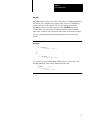
Header Files
Every source program must contain these two lines:
#include <stdio.h>
#include <H_6008SI.H>
STDIO.H is the standard header file supplied with your compiler.
H_6008SI.H is supplied on your scanner driver disk and defines constants,
variables, and functions that your program needs.
Your program may need other header files in addition to these two. If so,
you can add #include lines before or after the reference to H_6008SI.H.
However, H_6008SI.H must come later in your source file than STDIO.H.
Program Skeleton
Before making reference to any other routines in the scanner driver library,
your program must call either setup_6008 or start_6008 as described in
chapter 5, Startup.
After the last reference to other library routines, but before exiting, you
must call the stop_6008 function; please see the “Shutdown” section of
chapter 5. If your program crashes or exits normally without calling
stop_6008, you may have to reset the host computer (Ctrl-Alt-Del or
cycle power) to continue operating.
Between the startup and shutdown calls, your program must use the
host_active macro to tell the scanner that your program is still active.
By default, your program must do this at least once a second, but you can
change the interval through programming. For full discussion of safety
issues and programming, please see chapter 5, Host Watchdog.
4-7
Chapter 4
Programming Overview
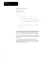
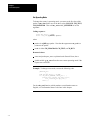
Here’s a sample program skeleton:
#include <stdio.h>
#include <h_6008si.h>
void main(argc, argv)
int argc; char *argv[
{
];
QMR pkt;
. . .
status = setup_6008(1, 1, 3, 0, &pkt);
if ( status != OK ) {
printf(“setup failed: command=%s status=%s\n”,
xlat_cmd(status), xlat_conf(pkt.qmr_stat));
if ( status != C_AUTOCONF && status != C_SETUP )
printf(“scanner fatal error %d\n”, fatal_6008(
));
abort( );
}
. . .
/* application logic here, including calls to host_active( )
*/
. . .
stop_6008( );
}
As explained in chapter 5, if setup fails the setup_6008 function returns
the number of the failed command and leaves the specific error status in
the packet. The sample above above uses xlat routines, described in
chapters 7 and 9, to display the meanings of the codes in plain English.
Once the setup procedure has succeeded, the scanner and host are talking
and your program can proceed. Your program must call host_active as
explained above.
Also, your program should periodically monitor global variable
g_act_scnr to make sure that communications are still active. (Refer to
chapter 5, Scanner Status, for complete information on g_act_scnr and
other scanner monitoring features.)
4-8
Chapter 4
Programming Overview
Defined Constants
In their appropriate places in this manual we’ll tell you about various
constants defined in the header file H_6008SI.H. There are three
constants that are not used by our routines but are defined for your
convenience, and we’ll list them now:
MAXGROUP is the maximum number of module groups, 64. Groups
in the I/O image tables are therefore numbered from 0 to
MAXGROUP-1.
MAXMOD is the maximum number of modules or slots, 132.
MAXADAPT is not the maximum number of adapters (which is 16) but
the number of possible adapter addresses, 32. (An adapter address is the
same as a quarter-rack address, 8 x rack +group / 2.) For instance, when
specifying fault dependent groups (chapter 7, “Scanner Management”)
you’ll give MAXADAPT group numbers to account for everywhere an
adapter might be addressed.
Defined Type Bool
It’s convenient to think of several variables and function values as
Boolean: that is, their value can be only true or false. We define the type
Bool for such values. Bool is equivalent to int, but use of a specially
defined type provides better program documentation.
We also define the two Bool constants OK and NOT_OK, equivalent to 0
and 1 respectively. This definition reflects the C language convention that
0 indicates no error and a nonzero value indicates an error.
Several library routines return status of OK or NOT_OK, and you can also
use those constants in your program. An example is presented in the user
diagnostic program source code, which we explain next.
Extended Example
Your distribution disk contains a complete sample program that exercises
all aspects of the scanner operation through commands you enter from the
keyboard. (Chapter 10, “User Diagnostic Program,” is a user’s guide for
the U_D1 program.)
Please take a minute to look at the source code for the main module,
U_D1.C. The program includes header files STDIO.H and H_6008SI.H
indirectly, through header file U_D1.H.
4-9
Chapter 4
Programming Overview
The main program displays identification on the screen and then calls
options (in the same source file) to read and interpret command line
options.
Next the main program calls init (also in the U_D1.C source file). In turn,
init calls setup_6008 and checks for status. If the setup was unsuccessful,
init displays a message and abort execution rather than returning to main.
If setup succeeded, init returns control to main. The main program then
goes into a loop that monitors the scanner activity code g_act_scnr and
calls pick (in source file U_PICK.C) to get a command from the
keyboard.When you enter a command to quit the program, pick returns a
status of NOT_OK to the main program, which terminates the main
program loop. The main program then calls stop_6008 and exits.
You’ll notice that we declare init and options as Bool type functions:
they’ll be returning a value of OK or NOT_OK. pick is declared Bool (in
the header file U_D1.H.) We also have a Bool variable called status that
we use as an “OK to proceed” sentinel. As soon as status takes on a value
of NOT_OK the remaining code is bypassed until the stop_6008
shutdown call.
You may also notice what looks like a violation of the rule we stated
earlier, that setup_6008 or start_6008 must precede calls to any other
routines in our library, and that no calls can follow stop_6008. Actually,
we oversimplified that rule when we stated it. The true rule is that
setup_6008 or start_6008 must be the first call that interacts with the
scanner and stop_6008 must be the last. But it’s OK to call any of the
following routines before startup or after shutdown: sysdate, systime,
sysstamp, pr_array, pr_globl (though some values displayed may not be
meaningful), xlat_cfg, xlat_cmd, xlat_conf, xlat_flt, xlat_opst.
Avoiding Compile Time Name Conflicts
When you write your program, you need to make sure that the variable
names you pick don’t conflict with the variable names in our library or
your compiler’s library. This section and the next tell you how to avoid
conflicts with our names; please consult your compiler manual for hints on
avoiding conflict with its names.
4-10
Chapter 4
Programming Overview
File H_6008SI.H defines constants according to a logical pattern. The
first few letters of each constant’s name tells you how it’s used, as follows:
Constant:
Definition:
C_
scanner commands (listed in chapter 7, Executing a Management Request, and
chapter 8, Queueing a Block Transfer)
CM_
scanner operating modes (program, test, and run; listed in chapter 7)
SC_
confirmation status values (listed in chapters 7 and 8, Confirmation Status Codes)
SF_
fault status bits and values (listed in chapter 7, Autoconfigure and Link Status
Information)
SL_
link (adapter) configuration status bits and values (listed in chapter 7, Autoconfigure
and Link Status Information)
SO_
operating status bits (listed in chapter 5, Scanner Status)
MAX
user program limits (listed above, in Defined Constants)
C compilers treat capitals and lower case differently, so it’s OK to select
names that begin with c_, cm_, and so on. But stay away from local or
global variable names beginning with any of the above character sequences
in capitals.
Avoiding Link Time Errors
You eventually link one of our supplied libraries with your program.
Please plan now to avoid naming conflicts. (You need to be concerned
only with the names of your functions and extern variables. Your static,
auto, and register variable names can’t conflict with ours.)
Link time name conflicts could show up in two ways. The linker could
refuse to create an executable program. But most likely the link would
proceed with no indication of anything wrong, and your routine would be
linked in and exclude our routine (or the compiler’s library routine) of the
same name. Then your program would crash (or give wrong results) when
one of our routines called your routine instead of the “standard” routine.
Bugs like these can be hard to uncover, so it’s best to avoid them in the
first place. Borland’s TLINK linker offers the /d option to diagnose this
sort of problem. We recommend you use the /d option if you’re using
Borland’s Turbo C++ or Borland C++ to develop your application.
In this manual you’ll see the names of almost all the functions in the
libraries we supply, and naturally you should not use any of those names
for your own code. In addition, the libraries have a few internal support
routines whose names begin with io_ or IO_, and you should avoid those
names also.
4-11
Chapter 4
Programming Overview
Names of global variables in our libraries begin with g_. In addition, the
libraries contain a number of undocumented internal global variables
whose names begin with _q.
In summary, you can create conflicts with names in our libraries by naming
functions and extern variables beginning with g_, _q, io_, or IO_. To be
safe, stay away from those names and from the names of functions
documented in this manual.
Compiling and Linking the
Borland C++ 2.0 Version
These notes present a simple way of compiling and linking your
application program with the scanner code. This way may or may not be
the best way for your development. There are many alternatives –
Borland’s Integrated Development Environment, make files and project
files, and so on. You should evaluate the alternatives and decide which
way is most productive for you.
Decide which memory model you will use (small, compact, medium, large,
or huge). Please see the discussion of memory models in your compiler
manual. In the command below, replace %%%% with the first letter of the
memory model, in lower case.
Use this command to compile and link your program in one step:
BCC –N –K –w –m%%%% –lcd yourprogname.c 6008si%%%%b.lib
Important: –lcd upper/lower case is significant in public names; diagnose
duplicate names in libraries.
The options we recommend are listed in Table 4.C.
Table 4.C
Options for Compile and Link
Options:
Description:
-N
stack checking turned on
-K
default 'char' is 'unsigned char'
-w
show warnings at compile time
-m
select memory model
-O
turn off optimization
-d
set up for debugging
-v
link with debugging information
We recommend against the –a option (align structure members by word).
Our library routines were compiled without it, and may not be compatible
with code you compile with that option.
4-12
Chapter 4
Programming Overview
For information on selecting or excluding the 8087 or 80287 math
coprocessor, please see the Borland manual sections on the –f options.
Our libraries are compatible with any –f option because they contain no
floating-point operations.
Example 1: Your program is called APPLIC.C. You have selected the
small (s) memory model. The combined command to compile and link
would be
BCC –N –K –w –ms –lcd applic.c 6008sisb.lib
Borland C++ will compile applic.c as applic.obj and link it as applic.exe.
Example 2: If your program is in several source modules, you can list
them on the command line. If you have chosen medium model, the
command is
BCC –N –K –w –mm –lcd control.c contr1.c contr2.c 6008simb.lib
The three source files will be compiled and linked as CONTROL.EXE.
Example 3: You have many source files –– U_D1.C, U_BT.C, and so on
–– to be compiled and linked in a program called U_D1B.EXE. Header
files are not in the same directory as source code, but are in directory
c:\dev\hdr. The following command will compile and link in small model.
BCC –N –K –w –ms –lcd –Ic:\dev\hdr –eU_D1B U_*.C 6008sisb.lib
This is quite similar to the command we used to create the U_D1B
program on your distribution disk.
Compiling and Linking the
Borland Turbo C++ 1.0 Version
The procedure is exactly the same as for Borland C++ 2.0, except that you
begin the command with TCC rather than BCC.
TCC –N –K –w –m%%%% –lcd yourprogname.c 6008si%%%%b.lib
4-13
Chapter 4
Programming Overview
Compiling and Linking the
Microsoft C 5.1 or 6.0 Version
These notes present a simple way of compiling and linking your
application program with the scanner code. This way may or may not be
the best way for your development. There are many alternatives –
Microsoft’s Programmer’s Workbench, make files, and so on. You should
evaluate the alternatives and decide which way is most productive for you.
Decide which memory model you will use (small, compact, medium, large,
or huge). Please see the discussion of memory models in your compiler
manual. In the command below, replace %%%% with the first letter of the
memory model, in upper case.
Use this command to compile and link your program in one step:
CL /J /A%%%% /W3 yourprogname.c /link 6008si%%%%m
The options we recommend are listed in Table 4.D.
Table 4.D
Options for Compile and Link
Options:
Description:
/J
default 'char' is 'unsigned char'
/A
select memory model
/W3
show warnings at compile time
/link
select scanner library
/Od
turn off optimization
/Zi
set up for CodeView debugging
We recommend against the /Zp option (pack structure members). Our
library routines were compiled without it, and may not be compatible with
code you compile with that option.
For information on selecting or excluding the 8087 or 80287 math
coprocessor, please see the Microsoft manual sections on the /FP options.
Our libraries are compatible with any /FP option because they contain no
floating–point operations.
Example 1: Your program is called APPLIC.C. You have selected the
small (S) memory model. The combined command to compile and link
would be
CL /J /AS /W3 applic.c /link 6008sism
Microsoft C will compile applic.c as applic.obj and link it as applic.exe.
4-14
Chapter 4
Programming Overview
Example 2: If your program is in several source modules, you can list
them on the command line. If you have chosen medium model, the
command is
CL /J /AM /W3 applic.c /link 6008simm
The three source files will be compiled and linked as CONTROL.EXE.
Example 3: You have many source files –– U_D1.C, U_BT.C, and so on
–– to be compiled and linked in a program called U_D1M.EXE. Header
files are not in the same directory as source code, but are in directory
c:\dev\hdr. The following command will compile and link in small model.
CL /J /AS /W3 /FeU_D1M /Ic:\dev\hdr U_*.C /link
6008sism
This is quite similar to the command we used to create the U_D1M
program on your distribution disk.
Further Information
The next few chapters of this manual explain programming features:
Chapter 5, Startup, Status, and Shutdown, explains features that must be
in every scanner interface program, including how to start and stop
scanner operation, status monitoring, and the host watchdog.
Chapter 6, Discrete I/O, explains how to read single-point inputs and
write outputs.
Chapter 7, Scanner Management, explains how to issue management
requests that modify the operation of the scanner.
Chapter 8, Block Transfer, explains how to read data from, and write
data to, intelligent I/O modules.
Chapter 9, General Support Features, explains how to write timing
loops, time-stamp a file or printout, and translate a numeric scanner
command to English.
4-15
Chapter 4
Programming Overview
The last two chapters are concerned with diagnostics:
Chapter 10, User Diagnostic Program, tells you how to use the
diagnostic program that we included on your distribution disks.
Chapter 11, Troubleshooting, has some questions and answers to help
you in diagnosing problems.
4-16
Chapter
5
Startup, Status, and Shutdown
Chapter Objectives
This chapter explains features that must be in every scanner program.
After reading this chapter, you should be able to write code that:
tells the scanner to start operation
lets the scanner know that your program is still active (the host
watchdog)
makes sure that the scanner is still active
checks the current operating status of the scanner
shuts down scanner operation in a way that leaves the scanner ready for
when your program runs again.
Overview
Every application begins with a call to setup_6008 or start_6008. Every
application makes one or more calls to host_active to satisfy the host
watchdog. Applications should check global variable g_act_scnr
periodically to make sure that the scanner is still active, though this is not
enforced. If your program finds from g_act_scnr that the scanner is no
longer active, you can call fatal_6008 to find out why. Finally, every
application must call stop_6008 before exiting.
CAUTION: If you are running a real-time control program,
screen dumps [Shift-PrtSc] cause the scanner to lose
communication with the host computer. Adapters on the I/O
link go to Last State or Reset, depending on their switch
settings. You must restart your system to re-establish
communication.
5-1
Chapter 5
Startup, Status, and Shutdown
Startup
In this section we’ll look at two functions that start the scanner and the
host talking to each other: start_6008 and setup_6008. Every application
uses one or the other, but not both. For most applications we recommend
setup_6008, which does more and is easier to use than start_6008.
Common Features
Both routines start the host watchdog, which your program must service
regularly. See chapter 5, ”Host Watchdog”, for more information.
Both routines also load the global variables g_ver_scnr and g_ver_host,
which are strings identifying the release of the scanner firmware and of the
host software driver. The scanner firmware version string g_ver_scnr is
no more than 39 characters long (38 plus the terminating zero byte), and
the host version string is 69 characters long (68 plus the zero byte). Your
program should display these strings so, that in case of trouble, you have
the information to give to A-B Technical Service.
setup_6008
setup_6008 initializes the interrupt handler and the global variables,
establishes communication with the scanner in program mode, and does
the initial baud and resistor setup (if required) and initial autoconfigure.
(For the meaning of autoconfigure, please see that section in chapter 7,
Scanner Management.)
Note: In the management request C_SETUP command, -1 indicates no
change.
Calling sequence:
status = setup_6008(baud, resistor, irq_l, segment, &packet);
Arguments:
baud: an integer representing the baud rate multiplier applied to the
board’s base rate of 57.6 Kbaud. At present only 1 and 2 are legal, for
57.6 and 115.2 Kbaud; or use -1 which means the default, 57.6 Kbaud.
resistor: an integer whose value is 1 if the line termination resistor is
connected and 0 if not; -1 means the default, resistor connected.
irq_l: an integer whose value is 3, 5, 10, or 12, depending on the
hardware interrupt line desired; -1 means the default, IRQ3, is selected.
segment: an unsigned representing the segment or paragraph address
of the global RAM. (Drop the final zero from the actual address to
obtain the paragraph address, which is the argument to this routine.) A
5-2
Chapter 5
Startup, Status, and Shutdown
value of 0 for this argument defaults to the factory-selected paragraph
address of C000h. Switches on the board are set to determine the global
RAM’s address in the host’s memory space, as explained in chapter 3,
Installation.
packet: a QMR packet, (see chapter 7, Scanner Management) into
which setup_6008 returns the autoconfigure information, or status in
case of error. Note that the argument is a pointer to the packet.
Returned values:
status: an integer: SC_OK 0(hex) if the setup proceeded without error,
C_AUTOCONF 10(hex) if the initial autoconfigure failed, C_SETUP
13(hex) if the setup call (changing baud rate or resistor) failed; any
other value means that the initial sync with the scanner failed.
If the returned value is SC_OK, your program’s packet contains the
information regularly returned by an autoconfigure.
If the returned value is anything but SC_OK, the specific nature of the
error is in the qmr_stat field of the packet that you passed to
setup_6008. Your program should display status information and abort
immediately.
Here’s the start of a sample program, showing a call to setup_6008 and
associated checks for error:
#include <stdio.h>
#include <h_6008si.h>
void main( )
{
QMR pkt;
int status;
. . .
status = setup_6008(-1, -1, -1, 0xC400, &pkt);
if ( status != OK ) {
printf(“setup failed: command=%s status=%s\n”,
xlat_cmd(status), xlat_conf(pkt.qmr_stat));
if ( status != C_AUTOCONF && status != C_SETUP )
printf(“scanner fatal error %d\n”, fatal_6008(
));
abort( );
}
else
mr_print(stdout, C_AUTOCONF, &pkt);
. . .
The declaration, QMR pkt, is explained in chapter 7, Data Structure.
5-3
Chapter 5
Startup, Status, and Shutdown
Look at the call to setup_6008. The first two arguments select the default
baud rate (57.6 Kbaud) and resistor setting (connected). The next two
arguments give the default interrupt request line setting (IRQ3) and the
paragraph address of the scanner, C400 (hex), which corresponds to C400
in the table in chapter 3, Installation. The fifth argument points to the
packet, which contains autoconfigure information if setup was successful
and an error code if it was not.
Next we test the status returned by setup_6008. If it’s not equal to OK (or
SC_OK; the two constants have the same value), we have a problem. In
this case the status is the number of the command that failed, and we
display a message using the translation routines described in chapter 9,
General Support Features, and chapter 7, Scanner Management. If the
status is neither C_AUTOCONF not C_SETUP, the host was unable to
establish communication with the scanner and the fatal_6008 routine gives
a code for the reason. If we couldn’t complete the setup operations, we
abort execution of the program.
NOTE: A common error returned from the fatal_6008 function is error
code 102. This usually means the RAM address set with the dip switches
on the scanner does not agree with the address argument in the setup_6008
function. Code 102 can also mean an addressing conflict with other
hardware in your PC. For most PC’s D800(hex) is usually free. Also
make sure the bus speed of your PC is not running faster than 8 Mhz.
If the setup operation did succeed, the host and the scanner are now talking
and your application program can proceed. In this example, we use
mr_print to display the initial configuration information.
The scanner is in program mode upon startup, and you’ll probably want to
change to run mode. For that procedure, see Set Operating Mode in
chapter 7, Scanner Management.
5-4
Chapter 5
Startup, Status, and Shutdown
start_6008
This function does a partial setup. Your program would call this function
rather than setup_6008 only when for some reason you want to
synchronize with the scanner but not set the baud rate and resistor and not
do an initial autoconfigure.
Calling sequence:
status = start_6008(irq_l,segment);
Arguments:
irq_l: same as under setup_6008 above.
segment: same as for setup_6008 above.
Returned values:
status: SC_OK 0(hex) if the sync proceeded without error,
SC_PENDING FF(hex) if the sync timed out, SC_NOT_OK 01(hex) if
the segment argument was illegal, SC_BAD_REQ 10(hex) if the
scanner had already been synchronized earlier in this execution,
SC_BAD_VERSN FE(hex) if the scanner firmware series didn’t match
the host, or a confirmation error status returned from the scanner.
If the returned status is anything but SC_OK, your program should
display the status value and the value of function fatal_6008, then abort
execution.
5-5
Chapter 5
Startup, Status, and Shutdown
Host Watchdog
Please refer to the Host Watchdog section in chapter 2, I/O Scanner
Concepts. That section explained the general concepts, this section
explains the specific programming steps.
host_active
This macro sets the host watchdog to a user- specified interval or to the
default.
By default, your program must call the host_active macro at least once a
second (18 units of 55 ms). You can select a different interval in any
host_active call, to be effective for that call only.
Calling sequence:
host_active(interval);
Arguments:
interval: a positive integer specifying the interval, zero to select the
default interval, or a negative value to disable the watchdog. Please see
the discussion below.
Returned values:
none.
g_act_host
When you call host_active, the specified positive number (or 18 if the
actual argument is zero) is placed in the global variable g_act_host.
Then every 55 ms the timer interrupt counts g_act_host down a notch.
When the scanner interrupts the host, the interrupt handler checks
g_act_host and if it’s negative the interrupt handler infers that the host
program is not active. The scanner goes off the link within 50 ms, all
adapters go inactive, and output terminals go to last state or reset. So your
program could bypass the host_active macro and just update g_act_host,
but the macro provides convenient program documentation.
You can disable the host watchdog by a one-time call to host_active with a
negative argument (which stores 0 in g_act_host). This may be
appropriate for strictly monitoring applications, but it’s almost certainly a
bad idea for control applications. You should be aware that disabling the
watchdog overrides the last state or reset switches and effectively sets all
discrete outputs at last state in case of a program failure.
5-6
Chapter 5
Startup, Status, and Shutdown
Scanner Status
This section tells you about three ways your program can monitor the
status of the scanner:
Global variable g_op_stat contains status bits that tell you the current
scanner operating mode and fault conditions. You can use the function
xlat_opst to convert the status bits to English.
Global variable g_act_scnr is positive as long as the scanner is still in
communication with the host.
Function fatal_6008 returns a code to describe the nature of the scanner
shutdown after it is no longer communicating with the host.
g_op_stat
At any time after the initial call to setup_6008 or start_6008, your
program can monitor the unsigned variable g_op_stat. This variable is a
set of bit fields, and you can test for a particular condition by ANDing a
symbolic constant with g_op_stat.
For instance, SO_FAULT is the symbolic name of the bit field that is true
(nonzero) when any adapters are faulted. To find out if any adapters are
faulted, your program would use this statement:
if ( SO_FAULT & g_op_stat )
/* one or more adapters are faulted */
else
/* no adapters are faulted */
5-7
Chapter 5
Startup, Status, and Shutdown
Table 5.A lists all of the bit fields in the global variable g_op_stat:
Table 5.A
g_op_stat bit field descriptions
Bit Field:
Hex Value:
Description:
SO_RUN
04 (hex)
The scanner is in run mode.
SO_PROGRAM
01 (hex)
The scanner is in program mode.
SO_TEST
02 (hex)
The scanner is in test mode.
SO_DEBUG
08 (hex)
The scanner is in debugging mode (scanner watchdog disabled).
For more on the scanner watchdog, see chapter 2., Scanner
Watchdog. For debugging mode, see chapter 7, Setup.
SO_BT_PEND
20 (hex)
One or more block transfers are pending in the scanner's queue.
SO_FAULT
40 (hex)
One or more adapters are in fault state.
SO_CHG_FLT
80 (hex)
The fault state of one or more adapters has changed. (This bit
must be reset by your program; the driver never resets it.)
SO_OIT_ERR
10 (hex)
If set, this bit indicates that your program has written one or more
valid module control bytes to the output image table, causing one
or more unsolicited block transfers. (Once set on, this bit remains
on until the user program resets it.) Please see chapter 8,
Unsolicited Block Transfer, for more information.
As mentioned previously, the SO_CHG_FLT and SO_OIT_ERR bits are
set by the driver but can only be reset by your program. Periodically,
probably once per program scan, your program should monitor these bits.
If the fault-change bit, SO_CHG_FLT, is set, your program should then
check SO_FAULT to determine the nature of the change. If the fault bit is
not set, the nature of the fault change was that the last faulted adapter came
back on line. But if the fault bit is set, your program should probably
execute a link status command (see chapter 7, Autoconfigure and Link
Status Information) to check which adapters are faulted. Here’s some
sample code, to be executed once per program scan:
if ( SO_CHG_FLT & g_op_stat ) {
g_op_stat &= ~SO_CHG_FLT;
if ( SO_FAULT & g_op_stat ) {
mr_wait(C_LINKSTAT, &link_pkt);
/* code to examine adapter status goes here */
}
}
In the first line of this example we test whether the fault state of any
adapters has changed; if so, we reset the fault-change bit. In the third line
we test the fault bit, and if any adapters are faulted we execute a link status
call to find out which ones. After the link status call, you would put code
to test the fault bits for each adapter, as explained in chapter 7,
Autoconfigure and Link Status Information.
For testing and resetting the SO_OIT_ERR bit (output image table
programming error), please see chapter 8, Unsolicited Block Transfer.
5-8
Chapter 5
Startup, Status, and Shutdown
xlat_opst
This function translates the operating status bits in g_op_stat to English.
Calling sequence:
explan = xlat_opst( );
Arguments:
None, since the operating status is a global variable.
Returned values:
a character pointer whose object is a string suitable for printing. The
string length does not exceed 80 characters (79 plus the terminating zero
byte).
Note that xlat_opst has an internal string buffer and returns a pointer to
that buffer. Calling xlat_opst destroys the previous contents of the buffer.
This means that you must use the string returned by this routine before you
call the routine again.
Here’s a typical use of this routine:
printf(“status: %s\n”, xlat_opst( ));
5-9
Chapter 5
Startup, Status, and Shutdown
g_act_scnr
This sentinel word (type integer) lets your program check periodically that
the scanner is still talking with the host. Here’s how it works.
This word is decremented once every 55ms; on the other hand, the
interrupt handler resets the value to 12 every time an interrupt from the
scanner is processed. Thus g_act_scnr goes negative about 1/3 of a
second (12K x 55ms) after the scanner last talks to the host.
Your program should poll for scanner failure by executing code similar to
the following once per program scan:
if ( g_act_scnr < 0 ) {
print(“\nscanner failure: code %d\n”, fatal_6008( ));
stop_6008( );
abort( );
}
The fatal_6008 and stop_6008 functions are explained later in this chapter.
Note that g_act_scnr goes on decrementing even after the scanner stops
talking to the host, so that it flips from negative to positive about half an
hour later.
5-10
Chapter 5
Startup, Status, and Shutdown
fatal_6008
This function obtains the scanner shutdown code, if available. Your
program should call this function, and display its result, whenever
g_act_scnr goes negative.
Calling sequence:
code = fatal_6008( );
Arguments:
none.
Returned values:
unsigned: 0 if the scanner is currently active, 1 if the scanner is inactive
but the function can’t obtain the actual code because the host doesn’t
have access to the global RAM (or because the scanner left no shutdown
code), or a value greater than 1 if the error code is obtainable.
If the global variable g_act_scnr is negative, either after a failed
setup_6008 or start_6008 or at any other time during execution,
fatal_6008 may return a meaningful error code. In that case, your
program should display the function value.
You should know about two special values that might be returned by
fatal_6008:
101 means that the interrupt handler let the scanner shut down
because your program hadn’t called host_active recently enough.
For more on this feature, please see chapter 5, ”Host Watchdog”.
102 means that your application program shut down interrupts
properly through the stop_6008 function, as described later in this
chapter. This code usually means that one of the setup parameters
in the SETUP command did not match the physical hardware
setting of the scanner. Recheck the scanner’s memory and
interrupt configuration.
CAUTION: If you ever get an error code other than 0, 101,
and 102 from fatal_6008, please call A-B immediately, because
a hardware or firmware problem with the scanner may have
occurred.
5-11
Chapter 5
Startup, Status, and Shutdown
Shutdown
Why is shutdown required?
Your application program must shut down the scanner properly before
exiting back to DOS. There are two reasons to do this:
An orderly shutdown puts all output modules into last state or reset,
according to the switches set on the I/O chassis. This would happen
without an orderly shutdown, but would take about 100ms longer.
When your program issued the original call to setup_6008 or
start_6008, the driver routines altered the DOS interrupt vectors to
point to library routines linked in your executable file. The shutdown
routine resets those interrupt vectors. If your program exits without
resetting the interrupt vectors, and you then try to run a program that
overlays the area pointed to by the altered interrupt vectors, the host
computer may lock up or behave erratically, requiring a hard reset or
cycling power before you can use it again.
stop_6008
This function de-installs the scanner interrupt code. If a setup_6008 or
start_6008 function has once been executed successfully, your program
must call this function before exiting.
Calling sequence:
stop_6008( );
Arguments:
none.
Returned values:
none.
Your program can omit the stop_6008 call only if the initial setup_6008 or
start_6008 call failed. However, an extra stop_6008 call does no harm,
even where it’s not needed.
5-12
Chapter
6
Discrete I/O
Chapter Objectives
This chapter explains how to use the functions contained in the host
software library to do discrete I/O. After reading this chapter, you should
be able to:
examine any discrete inputs
set or clear any discrete outputs
examine any outputs that you set or cleared previously.
You should be able to do all three of these either directly, by subscripting
into the I/O image tables, or indirectly, by using the supplied library
routines.
Direct Image
Table Access
The output and input image tables are two unsigned integer arrays of 64
words each, named g_oit and g_ipt respectively. You can directly read
either table using C language assignment statements, and you can directly
write to the output image table in the same way. (You can write to the
input image table to use unused input areas for storage. We do this
frequently in programmable controllers. However, with all the memory
available to you for storage in user RAM, we do not recommend using the
input image area for storage.)
The techniques, discussed in this section for accessing discrete I/O, execute
the quickest , but may be a little hard to understand. The techniques
discussed later in this chapter (see ”Library Routines”), sacrifice some
execution speed to gain some clarity. You’ll need to decide which
techniques are best for your application.
WARNING: Whichever technique you use to set outputs, make
sure that you don’t write to the output image table bytes that
correspond to intelligent I/O (block transfer) modules. If you do
write to these bytes, you’ll be unintentionally requesting a block
transfer. For more details, please see chapter 8, ”Unsolicited
Block Transfer”.
6-1
Chapter 6
Discrete I/O
Subscript Calculation
The image tables are tables of words, where each 16-bit word corresponds
to the 16 terminals of a module group. Terminal 17 octal (15 decimal)
corresponds to bit 017 (15 decimal) of the word, and so on down to
terminal 0 and bit 0. (16 bits times 64 words gives 1024 output terminals
and 1024 input terminals. Though possible, it is very unlikely that any
given application would use all I/O points.)
To address a particular module group in either the output or the input
image table, the subscript is 8 times the rack plus the group. For instance,
if you wanted to return the 16-bit contents of rack 2, group 7 from the
input image table, you could code it this way:
value = g_ipt[8*2+7];
Single Terminal
To access a single input terminal, you need to shift the word value and
AND a 1 to mask off the other bits. Remember to specify terminal
numbers in decimal, or use a leading zero if you’re specifying terminal
numbers in octal.
Example: to obtain the value of terminal 12 octal (10 decimal) from rack 3,
group 5, either of these statements works:
bit = g_ipt[8*3+5]>>012 & 1; or
bit = (g_ipt[8*3+5]>>10) & 1;
The first statement as coded depends on the C language’s operator priority:
shifts are done before ANDs. You may feel more comfortable adding
parentheses to emphasize the order of operations, as we did in the second
statement.
If you’re simply going to use a terminal value in an if test, you can shift it
as we did above, or you can use a one bit mask like this:
if ( g_ipt[8*3+5] & (1<<012) ) . . .
This doesn’t look much better than the previous construct, but if you define
symbolic constants (as we recommend) the code becomes clearer:
#define
#define
#define
#define
SENS_RACK 3
SENS_GRP 5
SENS_BIT 012
SENS_MASK (1<<SENS_BIT)
. . .
if ( g_ipt[8*SENS_RACK+SENS_GRP] & SENS_MASK ) . . .
6-2
Chapter 6
Discrete I/O
To set a single output terminal, you simply OR a 1 bit in the appropriate
position within the output image table word. Here’s an example, for
terminal 3 of rack 0, group 7:
g_oit[88*0+7] |=1<<3;
The next time the scanner scans that rack, the new value is transferred to
the scanner’s output image table and, the time after that, the value goes on
the I/O link to the module.
To reset (clear) a terminal is a little trickier: you have to AND a mask that
contains 1 bits everywhere except in the bit position of the terminal to be
cleared. The C language operator ~ is made for this kind of operation:
g_oit[8*0+7] &= ~(1<<3);
Access by Byte
If you need to access one slot within a module group, say to reset all eight
terminals in a single operation, you have two ways to do it. You could use
a cast operator to access the image table as an array of 128 character
values, or you could use the masking technique shown above.
Example: to clear slot 12 (the left hand slot of group 6) of rack 2, you can
do either
g_oit[8*2+6] &= 0xFF00;
or
*((char *)g_oit + 16*2+12) = 0;
Notice in the first example that the low byte of a constant occurs at the
right, even though the low slot is physically at the left in the chassis. (The
bytes within a word are stored with the low byte at the lower address,
backward from the way the numbers occur in computations.) In the second
example, notice that we have 16 bytes rather than 8 words per rack.
Programming Hint
We suggest that you define constants for the addresses of your I/O
modules. This makes your programs easier to understand, and helps you in
debugging. For example:
#define ALARM_RACK 5
#define ALARM_GRP 0
#define ALARM_TERM 017
. . .
g_oit[8*ALARM_RACK+ALARM_GRP] |= 1<<ALARM_TERM;
6-3
Chapter 6
Discrete I/O
Let’s look at this example. We defined the rack and group of the module
that controls an alarm, and the specific terminal (note the leading zero for
octal notation). To turn on an output terminal, we shifted a 1 bit left by the
terminal number and ORed that into the output image table.
By the way, you may be wondering about efficiency. Most C compilers do
all arithmetic on constants at compile time. So at run time there would be
no difference in execution speed between the above statement and
g_oit[40] |= 0x8000;
but the first way is certainly easier to understand and maintain.
Library Routines
We provide you with several library routines and macros to access the I/O
image tables. Execution is not as efficient as with the direct addressing
techniques in the previous section, but the difference should be negligible
in most applications compared to the time for transferring data across the
link.
getbit
Use this routine to get a bit from the input or output image table.
Calling sequence:
value = getbit(inout, rack, group, bit);
Arguments:
inout: the constant IN (1) for input image or OUT (0) for output
image.
rack: an integer 0 to 7, the logical rack number.
group: an integer 0 to 7, the module group number.
bit: an integer 0 to 15 (octal 0 to 017), the bit or terminal number.
Returned values:
an integer, the value of the bit, 1 or 0.
Example:
sens_bit = getbit(SENS_RACK, SENS_GRP, SENS_BIT);
obtains an on or off value from the sensor, assuming that you have
defined the symbolic constants in your program.
6-4
Chapter 6
Discrete I/O
getbyte
Use this routine to get an 8-bit byte from the input or output image table.
Calling sequence:
value = getbyte(inout, rack, group, hilow);
Arguments:
inout: the constant IN (1) for input image or OUT (0) for output
image.
rack: an integer 0 to 7, the logical rack number.
group: an integer 0 to 7, the module group number.
hilow: the logical constant HI (1) or LO (0) to select the high or low
byte. The high byte corresponds to slot 1 within a module group
(terminals 017-010), and the low byte to slot 0 (terminals 07-00).
Returned values
a character, the value of the byte.
getword
Use this routine to get a 16-bit word from the input or output image table.
Calling sequence:
value = getword(inout, rack, group);
Arguments:
inout: the constant IN (1) for input image or OUT (0) for output
image.
rack: an integer 0 to 7, the logical rack number.
group: an integer 0 to 7, the module group number.
Returned values:
an unsigned integer word, the value in the image table for that module
group.
6-5
Chapter 6
Discrete I/O
putbit
Use this routine to write a bit into the output image table.
Calling sequence:
putbit(data, rack, group, bit);
Arguments:
data: an unsigned integer, whose low order bit is to be written to the
output image table.
rack: an integer 0 to 7, the logical rack number.
group: an integer 0 to 7, the module group number.
bit: an integer 0 to 15 (decimal) or 0 to 17 (octal), the bit number.
Returned values:
none
6-6
Chapter 6
Discrete I/O
setbit
Use this routine to write a one bit into the output image table.
Calling sequence:
setbit(rack, group, bit);
Arguments:
rack: an integer 0 to 7, the logical rack number.
group: an integer 0 to 7, the module group number.
bit: an integer 0 to 15 (decimal) or 0 to 17 (octal), the bit number.
Returned values:
none.
Example:
setbit(ALARM_RACK, ALARM_GRP, ALARM_TERM);
turns on the alarm if the three constants have been defined with the rack,
group, and terminal (bit) number.
Note: setbit is a macro that compiles into a call on putbit with a
constant data value of 1.
6-7
Chapter 6
Discrete I/O
clrbit
Use this routine to write a zero bit into the output image table.
Calling sequence:
clrbit(rack, group, bit);
Arguments:
rack: an integer 0 to 7, the logical rack number.
group: an integer 0 to 7, the module group number.
bit: an integer 0 to 15 (decimal) or 0 to 17 (octal), the bit number.
Returned values:
none.
Note: clrbit is a macro that compiles into a call on putbit with a
constant data value of 0.
putbyte
Use this routine to write an 8-bit byte to the output image table.
Calling sequence:
putbyte(data, rack, group, hilow);
Arguments:
data: an unsigned integer whose low order byte is written to the output
image table.
rack: an integer 0 to 7, the logical rack number.
group: an integer 0 to 7, the module group number.
hilow: the logical constant HI (1) or LO (0) to select the high or low
byte. The high byte is slot 1 (terminals 17-10) of the module group; the
low byte is slot 0 (terminals 07-00).
Returned values:
none.
6-8
Chapter 6
Discrete I/O
putword
Use this routine to write a 16-bit word to the output image table.
Calling sequence:
putword(data, rack, group);
Arguments:
data: an unsigned integer to be written to the output image table.
rack: an integer 0 to 7, the logical rack number.
group: an integer 0 to 7, the module group number.
Returned values:
none
Print or Display
Image Table
This section describes a routine we provide to help you dump the input or
output image table, or any array, to screen, printer, or disk. You can dump
the array by byte (16 per line) or by word (8 per line).
pr_array
Use this routine to format a word or byte array for display.
Calling sequence:
pr_array(fileptr, header, array, length);
Arguments:
fileptr: stdout or stderr for output to screen, or a pointer to a file
opened by the user program through fopen.
header: a character pointer whose object is a descriptive phrase of a
few characters, such as “IIT”. If the display is to fit on an 80- character
line, the length of the header string must not exceed 34 characters if the
array is word oriented, 26 if byte oriented.
array: the name of a character or unsigned integer array.
length: an integer giving the length of the array. If the array is to be
displayed as words, length should be a positive number. If the array is
to be displayed as single bytes (type chararacter), length should be
minus the number of bytes in the array.
6-9
Chapter 6
Discrete I/O
Returned values:
none.
Example: dumps the output image table by words to the screen.
pr_array(stderr, “output image”, g_oit, MAXGROUP);
Example: dumps the scan list from a management request packet to a
file by bytes. Here filrec is the value returned by an earlier call to the
standard library routine fopen, which is supplied with your compiler.
pr_array(filrec, “scan list”, pkt.qmr_data, -pkt.len);
Timing of
Discrete I/O
It’s important to bear in mind that when you update your output image
table there is not an immediate effect on the outside world. (Though we
talk about output in this section the same timing applies to input: it takes as
long for a new input value to find its way from the input module to your
program as it does for an output value to follow the reverse path.)
Here is the chain of events for an output:
Your program updates g_oit, your output image table, either directly or
by using a library routine.
Some time later, the scanner interrupts the host.
The host interrupt handler (which runs in background as far as your
program is concerned) copies from the scanner’s input image table to
g_ipt, your input image table, and copies from g_oit to the scanner’s
output image table.
If the interrupt occurred just after you changed the output, the new data
is transferred when the scanner has run through its entire scan list back
to the point of the last interrupt. (The scanner interrupts the host once
per scan list to refresh I/O in both directions.)
Later the scanner comes to the adapter associated with the changed data,
and sends the new information to the adapter.
6-10
Chapter 6
Discrete I/O
This sequence of events could take as long as two passes through the scan
list. This worst case scenario happens when you update an output just after
the scanner and the host interrupt handler have refreshed that rack. So it
may take one cycle until the scanner gets the new value, and a second
cycle until it services the adapter and sends the changed output.
How long is a cycle? Multiply 11 milliseconds (7 ms at 115.2 Kbaud) by
the number of adapters in the scan list. Your program has no way to know
where the scanner is in the scan list, or when the refreshes take place, so if
timing is critical you must assume that outputs might not get out to the real
world for as long as two complete scan lists if each adapter occurs only
once. (You can improve the situation by putting a critical adapter at two
different points in the scan list; see the scan list command in chapter 7,
”Scan List”.)
Partial Refresh
You can force a partial refresh sooner than the worst case of two complete
passes through the scan list. This makes the scanner’s latest input
information available to your program and send the scanner new discrete
outputs for those same racks. However, your program has no way to
update specific racks or adapters, or to know which racks have just been
refreshed.
We don’t know of an application that would require such an interim
refresh, but if you decide yours is one here is how to refresh the I/O image
tables early.
Note: It may bear repeating that update merely updates I/O image tables;
it does not assure your program that any I/O has actually occurred.
update
Use this routine to refresh the I/O image tables.
Calling sequence:
status = update( );
Arguments:
none.
Returned value:
OK if the scanner responded before the timeout period specified by
g_timout; NOT_OK if the scanner did not respond.
6-11
Chapter 6
Discrete I/O
This routine interrupts the scanner, then waits until the scanner has
interrupted the host at least once. The host’s interrupt handler updates the
global RAM from the user program’s output image tables and the user
input image tables from the global RAM. After the interrupt has been
processed, update returns control to your program.
6-12
Chapter
7
Scanner Management
Chapter Objectives
This chapter explains how to issue management requests to the scanner.
After reading this chapter, you should be able to:
queue any of the six types of management requests
print or display the results, or write formatted results to a file.
To make this chapter shorter and easier to read, we use the abbreviation
MR for management request.
Overview
Here is a summary of the actions involved in completing an MR:
Your program puts the data (for all commands except autoconfigure and
link status) and length of data (for scan list only) into a packet of
specified structure.
Your program calls the mr_wait library routine.
mr_wait copies information to an internal queue and interrupts the
scanner. mr_wait does not return to your program but instead goes into
a wait loop, which ends when the request is done or g_timout units of
time have elapsed.
When the scanner responds (usually a short time later), the interrupt
handler copies the MR information to the global RAM. This happens
essentially in background as far as mr_wait is concerned.
When the scanner comes back a second time with a completion status,
the interrupt handler copies that status (plus the length of data and the
data, for autoconfigure and link status) to your program’s packet.
Again, this is in background as far as mr_wait is concerned.
When mr_wait senses in its loop that the request is complete, it returns
control to your program. If the timeout interval runs out before the
scanner comes back with a confirmation, mr_wait returns to your
program anyway.
7-1
Chapter 7
Scanner Management
Data Structure (Packet)
QMR typedef
When you initiate an MR, you pass a packet to the library routines. The
packet has a defined type of QMR.
This defined type is a structure that contains a field used only by the
library routines, plus the following:
qmr_stat
unsigned integer confirmation status, initially equal to SC_PENDING
and then set to the actual completion status after the scanner has finished
with the MR.
qmr_len
unsigned integer length of data in bytes, which you fill in only when
changing the scan list.
qmr_data
character array of 128 bytes, the data area.
Programmer Alert
Your program can get itself into trouble by misusing packets. Here are the
pitfalls that relate to MRs:
Improper reuse of pointers: If the mr_wait routine decides that the
scanner has not responded in a reasonable time, your program is
generally free to use the packet for a different MR. But suppose that
your program had g_timout set too low so that mr_wait didn’t wait
long enough. (A scan list, the slowest request, can take up to 12 units,
about 2/3 of a second.) Then the confirmation of the first request could
come through and wipe out the information in the second request, which
is waiting for a confirmation from the scanner. The library routines
catch some but not all of these situations, and count up the ones they do
catch in g_pkt_err. Generally, your program should not reuse a packet
that contains a status of SC_PENDING unless absolutely sure that the
scanner never responds to that command.
Invalid pointers: Conforming to established C coding conventions,
library routines that need access to user packets take pointers as their
function arguments. There is no way for a called function to check
whether your program has sent it a valid pointer. Therefore, you are
completely responsible for sending valid pointers to the library routines.
If the pointer arguments don’t point to proper packets, your program can
perform incorrectly or crash, possibly locking up the host computer.
7-2
Chapter 7
Scanner Management
Executing a Management
Request
To start an MR, you store the required fields in the packet and then call the
mr_wait function. mr_wait waits until the request is completed or has
timed out and returns a completion status to your program.
Autoconfigure, setup, scan list, and fault dependent group can be executed
only in program mode. Link status and set mode can be executed in any
mode.
Timeout
The timeout period is the current value of global variable g_timout in 55
millisecond units. (The actual frequency is more nearly 1,193,180 / 64K
Hz, about 18.2065 per second or 54.925 ms each.) If the scanner doesn’t
complete the MR within this time, mr_wait assumes that the scanner never
completes the request.
The default timeout is 18 units, about 1 s. You can change the timeout
interval by storing a new value in g_timout. However, be sure to allow a
large enough interval. Worst-case times for autoconfigure and scan list are
272 ms and 704 ms respectively; for full explanations please see those
sections. Link status, set operating mode, fault dependent group, and setup
are always completed within one time unit, 55 ms.
The actual timeout interval can be as much as one unit less than the value
you store in g_timout. The reason is that the mr_wait routine copies
g_timout to the g_decrem counter, which counts down every 55 ms, and
when g_decrem reaches zero the mr_wait function considers the request
to have timed out. But if the clock tick happens to come right after
g_decrem was set, the effective value of the timeout is almost a full 55 ms
less that the nominal value. The bottom line? In deciding on a timeout (if
you don’t stick with the default value), always allow an extra unit above
the value you calculated.
7-3
Chapter 7
Scanner Management
General Form
This section gives details for each of the six types of MR, but first we
present a program skeleton, where command stands for the defined
constant that names the desired command:
QMR mgmt;
unsigned confirm_stat;
. . .
mgmt.qmr_len = . . .
/* for scan list only */
mgmt.qmr_data[0] = . . . /* except autoconf & link */status
confirm_stat = mr_wait(command, &mgmt);
if ( !confirm_stat ) {
/* successful completion */
}
else {
/* unsuccessful completion */
}
mr_print(stderr, command, &mgmt); /* if display wanted */
The mr_print call shown in the program skeleton above displays the
results of the MR on the screen. Such a call would probably be used only
when operator intervention might be appropriate.
7-4
Chapter 7
Scanner Management
mr_wait
mr_wait returns a status code, which it also places in the qmr_stat field of
the packet. For a complete list of status codes, please see Confirmation
Status Codes later in this chapter. For now it’s enough to know that
SC_OK (0) means successful completion, SC_PENDING means the
scanner didn’t come back with a confirmation before timeout, and any
other value is an error code returned by the scanner or the library routines.
You can code if tests based on the assumption that a zero status means
success.
Example:
if ( mr_wait(. . .) )
/* request failed */
or
if ( !mr_wait(. . .) )
/* request succeeded */
If you prefer, you can call mr_wait without using its return value, since
the qmr_stat field of the packet contains the same code:
mr_wait(. . ., &pkt);
if ( pkt.qmr_stat )
/* request failed */
7-5
Chapter 7
Scanner Management
Set Operating Mode
To change the scanner’s operating mode, you must set the first byte of the
packet’s qmr_data field to one of the three values CM_RUN, CM_TEST,
CM_PROGRAM. Then call mr_wait with C_SETMODE as its first
argument.
Calling sequence:
packet.qmr_data[0] = mode;
status = mr_wait(C_SETMODE, &packet);
where
packet is a QMR type packet. Note that the argument to mr_wait is a
pointer to the packet.
mode is either CM_PROGRAM, CM_TEST, or CM_RUN.
Returned values:
status and packet.qmr_stat as explained under General Form, above.
global variable g_op_stat reflects the new scanner operating mode if the
request was successful.
Example: To change to run mode, execute the following code:
QMR mode_pkt;
. . .
mode_pkt.qmr_data[0] = CM_RUN;
if ( mr_wait(C_SETMODE, &mode_pkt) ) {
printf(“can’t execute set mode (%s)\n”,
xlat_conf(mode_pkt.qmr_stat));
abort( );
}
For the xlat_conf function, which translates a confirmation status to
English, see Confirmation Status Codes later in this chapter.
7-6
Chapter 7
Scanner Management
Setup
This MR lets you change the baud rate and connect or disconnect the line
termination resistor. It also lets you put the scanner into “debugging
mode,” which disables the scanner watchdog. The scanner must be in
program mode to execute a setup request; otherwise the scanner returns an
error code.
Note: In the SETUP_6008( ) function, -1 indicates default parameters.
The symbolic name of the setup command is C_SETUP. The setup
request takes three bytes of data:
baud rate, 1 for 57.6 Kbaud, 2 for 115.2 Kbaud, or -1 to leave the
present baud rate unchanged.
resistor, 1 to connect, 0 to disconnect, or -1 for no change.
debugging mode, 1 to disable the scanner watchdog and any other value
to enable the watchdog. Debugging mode is discussed below.
WARNING: Debugging mode should be used only when
someone is physically present to monitor the process. If the
host program stops while scanner debugging mode is in effect,
all output modules stay in last state. You should shut off the
host computer’s power switch immediately to terminate the
process.
Calling sequence:
packet.qmr_data[0] = . . .
/* baud rate */
packet.qmr_data[1] = . . .
/* resistor */
packet.qmr_data[2] = . . .
/* debugging mode */
status = mr_wait(C_SETUP, &packet);
where
packet is a QMR type packet. Note that the argument to mr_wait is a
pointer to the packet.
Returned values:
status and packet.qmr_stat as explained under General Form, above.
global variable g_op_stat reflects whether the scanner is in debugging
mode (SO_DEBUG bit).
7-7
Chapter 7
Scanner Management
Example: If you want to switch to 115.2 Kbaud without changing the
resistor setting, use this code:
QMR setup_pkt;
. . .
setup_pkt.qmr_data[0] = 2; /* baud multiplier */
setup_pkt.qmr_data[1] = -1; /* no change to resistor */
setup_pkt.qmr_data[2] = 0; /* not in debug mode */
mr_wait(C_SETUP, &setup_pkt);
if ( setup_pkt.qmr_stat ) {
printf(“setup call failed (%d)\n”,
setup_pkt.qmr_stat);
abort( );
}
A note on debugging mode: Normally, the scanner expects the host to
return the global RAM within 50 milliseconds after the scanner interrupts
the host. (This is a comfortable margin: the host interrupt service routine
takes about 0.1 to 2 ms, depending on the host CPU and how much work
the interrupt routine has to do.)
After the 50 ms interval, the scanner watchdog kicks in. What that means
is that the scanner decides that the host hardware or BIOS has died and
therefore the scanner goes off the I/O link. In about another 50 ms the
adapters all go inactive and the modules are in last state or reset according
to the way you set their switches. Normally, this safety precaution is
exactly what you want.
But if you’re debugging your program you may want to single step through
it, and each step would take longer than the scanner’s 50-ms watchdog
interval. This is the purpose of debugging mode: it turns the scanner
watchdog off.
Make sure to turn debugging mode off (a setup request with any value
other than 1 in the third byte) before your program exits. If your program
ends while the scanner is in debugging mode, you have to cycle power
before the scanner communicates with the host again. (In this case you
should turn off host power anyway, as a safety measure, since otherwise all
output modules are held in last state.)
7-8
Chapter 7
Scanner Management
Autoconfigure
In doing an autoconfigure, the scanner actually queries each possible
adapter position to determine which addresses have adapters present.
To tell the scanner to do an autoconfigure, you simply issue an mr_wait
function call with C_AUTOCONF as its first argument. The scanner must
be in program mode to do an autoconfigure; otherwise the scanner returns
an error status.
When the scanner does an autoconfigure, it forgets any fault dependent
groups you may have set up. When doing an autoconfigure, the scanner
also puts a new default scan list into effect. The default scan list is simply
a list of all adapters that responded, in rack and group order. (In single slot
addressing, a single adapter with more than eight slots looks like two
adapters to the scanner.)
Calling sequence:
status = mr_wait(C_AUTOCONF, &packet);
where:
packet is a QMR type packet. Note that the argument to mr_wait is a
pointer to the packet.
Returned values:
status and packet.qmr_stat as explained under General Form, above.
packet.qmr_data contains 32 words of configuration information, one
for every possible adapter address, followed by 0 to 16 bytes of the
current scan list; see discussion below.
packet.qmr_len contains the length of data in bytes, which is 64 plus the
length of the new default scan list. In other words, to obtain the length
of the scan list you subtract 64 from packet.qmr_len.
Before we give you further information on interpreting the data returned
by an autoconfigure, you should know that we have provided a routine,
mr_print, to turn all the information into English. For details, please
see ”Print or Display Results” in this chapter.
7-9
Chapter 7
Scanner Management
The data returned by a successful autoconfigure can be divided into two
parts:
a fixed length part, 32 pairs of bytes. The first byte of each pair gives
information about the size and type of the adapter, and the second byte
gives fault information. For complete information, please see
”Autoconfigure and Link Status Information” in this chapter.
a variable length part, 0 to 16 bytes long, containing the new default
scan list. Each byte contains an adapter position in the form 4 x rack +
group / 2. The length of the scan list is packet.qmr_len – 2 x 32.
The time required to complete an autoconfigure request depends on the
baud rate and the number of adapters connected, as well as the size of each
adapter. For simplicity, we consider worst case, where each adapter
controls a full rack. In this case, the time to completion is 11 milliseconds
per connected adapter (7 ms at 115.2 Kbaud) plus 6 ms for each of the 32
possible adapter positions where no adapter is connected. Doing the
algebra, we have
T = 5 ms x adapters + 192
T = 1 ms x adapters + 192
(57.6 Kbaud)
(115.2 Kbaud)
Since no more than 16 adapters can be connected at once, worst-case time
for an autoconfigure is 272 ms at 57.6 Kbaud, 208 ms at 115.2 Kbaud. (If
16 adapters are connected, they can’t all be full racks, so this is actually a
longer time than true worst case.)
Link Status
A link status request returns the same information as an autoconfigure, but
link status differs from autoconfigure in three ways:
The scanner can execute a link status request while in any mode, not just
program mode.
The scanner doesn’t actually query possible adapters in doing a link
status. Rather, the scanner copies its internal status tables to the global
RAM.
Fault dependent groups and the current scan list are not changed by a
link status command.
7-10
Chapter 7
Scanner Management
To query the scanner about link status, simply issue an mr_wait function
call with C_LINKSTAT as its first argument.
Calling sequence:
status = mr_wait(C_LINKSTAT, &packet);
where:
packet is a QMR type packet. Note that the argument to mr_wait is a
pointer to the packet.
Returned values:
status and packet.qmr_stat as explained under General Form, above.
packet.qmr_data and packet.qmr_len contain exactly the same
information as is returned by an autoconfigure, except that the scan list
and fault dependent groups have not been disturbed. The scan list
length may also be up to 64 bytes long rather than just 16. For complete
information, please see ”Autoconfigure and Link Status Information”
later in this chapter.
Scan List
You can use a scan list request to tell the scanner to give a larger share of
its attention to some adapters at the expense of others. Though there are
only 32 possible adapter addresses, and only 16 of those can be occupied at
a time, the scan list can be up to 64 positions long.
The scan list and fault dependent group requests interact in one way:
Every adapter that is part of a fault dependent group must also be part of
the current scan list. If you try to violate this rule by specifying a new scan
list, one that omits some adapters that are still in fault groups, the scanner
returns an error code and leaves the old scan list in effect. To change the
scan list in that way you must first issue a fault dependent group command
that leaves the “orphan” adapters out of all fault groups.
7-11
Chapter 7
Scanner Management
The scan list request is the only MR that requires both data and length of
data to be in the packet before you call mr_wait. The first argument to
mr_wait is C_SCANLIST. The scanner must be in program mode to
execute a scan list request; otherwise the scanner just returns an error code.
Calling sequence:
packet.qmr_len = . . .
/* length of scan list, 0-64 */
packet.qmr_data[0] = . . . /* first adapter address */
packet.qmr_data[1] = . . . /* second adapter address */
. . .
packet.qmr_data[length-1] = . . . /* last adapter address */
status = mr_wait(C_SCANLIST, &packet);
where
packet is a QMR type packet. Note that the argument to mr_wait is a
pointer to the packet.
packet.qmr_len, the length of the scan list, may be anything from 0 to
64 inclusive.
packet.qmr_data contains the adapter addresses for the scan list, in the
form 4 x rack + starting group / 2. A given adapter can occur more than
once in the list, or an existing adapter may be omitted from the scan list.
Returned values:
status and packet.qmr_stat as explained under General Form, above.
The time required to complete a scan list command is essentially the
time to scan every adapter once: 11 milliseconds per scan list entry (7
ms/entry at 115.2 Kbaud). Since the scan list can be as long as 64
entries, the worst case time is 704 ms at 57.6 Kbaud, 448 ms at 115.2
Kbaud.
7-12
Chapter 7
Scanner Management
Example: Suppose you have two adapters connected, one controlling rack
1 (a full rack) and the other controlling the second half of rack 2. (The
adapter addresses are 4 x 1 + 0 / 2 = 4 and 4 x 2 + 4 / 2 = 10.) Suppose
you want to sample inputs from rack 2 every 5 seconds, but want the most
current information possible from rack 1. You would enter a scan list
request with adapter 2 occurring only once and adapter 1 occurring several
times.
At first glance, you might try a scan list of 64 bytes, with 63 repeats of
adapter 1 and one occurrence of adapter 2. (Since the scan list is processed
repetitively, it doesn’t matter where in the list the one occurrence of rack 2
is placed.) But if you want the most current information possible that may
not be a good idea.
Recall that it takes up to 11 ms at 57.6 Kbaud, or 7 ms at 115.2 Kbaud, to
scan each adapter in the scan list. If you’re operating at 115.2 Kbaud with
a scan list of 64 positions, your inputs are updated only every 64 x 7 = 448
ms. If you want information, say, every 100 ms, then you need a shorter
scan list. 100 / 7 = 14.3, so you want a scan list only 14 or 15 positions
long.
Here is code to create that scan list, using the memset function (provided
with many compilers) to initialize a block of memory:
QMR scan_list;
. . .
scan_list.qmr_len = 14;
/* length of scan list */
/* 13 occurrences of first adapter */
memset(scan_list.qmr_data, 4, 13);
scan_list.qmr_data[13] = 10; /* second adapter */
mr_wait(C_SCANLIST, scan_list);
if ( scan_list.qmr_stat )
/* error code here */
Fault Dependant Group
In many applications, adapters are conceptually grouped together such that
if any one of the adapters in a group is faulted, you want all the others to
be faulted too. The fault dependent group (FDG) request implements this
concept.
FDGs are numbered from 0 to 7. When you issue a FDG request, you
specify which adapters should be put in FDGs and which FDGs they
should be put in.
7-13
Chapter 7
Scanner Management
In the data array, you must fill the first 32 bytes, one for each possible
adapter position. The subscripting is 4 x rack + group / 2. (In the subscript
calculation, group is the adapter’s starting group number within the rack,
not the FDG number.) For each adapter position, if the adapter doesn’t
exist, or it exists but you don’t want it to be in a fault group, put zero in the
data byte. For each existing adapter that is in the current scan list and that
you want in a fault group, put the fault group number ORed with
SF_IN_FGRP in the data byte.
Note that an adapter is not allowed to be in an FDG unless it is also in the
current scan list. If you want to increase the scan list and put the added
adapters in fault groups, you must issue two commands in that order. If
you try to issue a FDG request that puts unscanned adapters in fault
groups, the scanner returns an error code and does not change the existing
fault groups.
Once you’ve set up the data array, call mr_wait with a first argument of
C_FLT_GRP. The scanner must be in program mode to execute a FDG
request; otherwise the scanner returns an error code.
Calling sequence (example):
packet.qmr_data[...] = 0; /* no fault group */
packet.qmr_data[...] = 1 | SF_IN_FGRP; /* fault group #1 */
. . .
packet.qmr_data[...] = 0 | SF_IN_FGRP; /* fault group #0 */
status = mr_wait(C_FLT_GRP, &packet);
where
packet is a QMR type packet. Note that the argument to mr_wait is a
pointer to the packet.
packet.qmr_data contains the fault group numbers for the 32 possible
adapter addresses, four per rack.
Returned values:
status and packet.qmr_stat as explained under General Form, above.
7-14
Chapter 7
Scanner Management
Example: Suppose you have five adapters connected, four for the quarter
racks in rack 6 and one for the first half of rack 0. If you want to link the
four quarter-rack adapters in a fault dependent group, say group 1, and
leave the half-rack adapter out of all FDGs, you can do it this way:
QMR fdg;
. . .
memset(fdg.qmr_data, 0, MAXADAPT);
memset(fdg.qmr_data+6*4, 1|SF_IN_FGRP, 4);
if ( mr_wait(C_FLT_GRP,&fdg) )
/* error code here */
Autoconfigure and
Link Status Information
The autoconfigure and link status requests return a complicated data
structure in the qmr_data field of the packet:
The first part is fixed length and contains 32 words (byte pairs), one for
each possible adapter position. Within each byte pair, the first byte
contains configuration information, such as the size and type of the
adapter, and the second byte contains fault status and fault dependent
group information.
The second part is variable length, being the current scan list, 0 to 64
bytes long. The length of the scan list is found by subtracting 64 from
the value in the qmr_len field of the packet. Each byte contains an
adapter address in the form 4 x rack + group / 2.
Here is some quick code to print the current scan list:
int len;
char *scan;
. . .
len = packet.qmr_len - 2*MAXADAPT;
if ( !len )
printf(“scan list has no adapters\n”);
else
printf(“current scan list (%d adapters):\n”, len);
for ( scan=packet.qmr_data+2*MAXADAPT; len--; ++scan )
printf(“rack %d group %d\n”, *scan>>2, (*scan&3)<<1);
Most of this section explains how to extract the configuration and fault
information, working from the packet that was returned by a successful
autoconfigure or link status request.
7-15
Chapter 7
Scanner Management
Configuration Information
Byte
You can extract the configuration information byte for any adapter, based
on the rack and starting group of the adapter. Either access an element of
the qmr_data array, like this:
packet.qmr_data[ 8*rack + group ]
or use the cfg_info macro to do the same thing.
cfg_info
This macro obtains the configuration byte for a particular adapter from the
QMR-type packet returned from an autoconfigure or link-status request.
Calling sequence:
status = cfg_info(&packet, rack, group);
Arguments:
packet: a QMR structure, assumed to contain status SC_OK after an
autoconfigure or link status request. Note that the actual argument is a
pointer to the packet.
rack: logical rack number, 0 to 7.
group: starting group number, an even number from 0 to 6.
Returned values:
an integer that can then be examined for the status bits described below
(leading characters SL_). If you prefer, you can call the xlat_cfg
function to convert the status bits to an English language string; see
”Print or Display Results” in this chapter.
7-16
Chapter 7
Scanner Management
Configuration Information Bit Fields
The fields listed in Table 7.A are defined in the low byte of the word of
information about each adapter, which can be extracted by using the
cfg_info function described above:
Table 7.A
Configuration Information Bit Field Descriptions
Bit Field
Hex Value
Description
SL_IN_SCAN
10 (hex)
true (1) if the adapter is in the current scan list. If this bit is
zero, the other bits in the link status word are meaningless.
SL_EXISTS
08 (hex)
true (1) if an adapter is attached (or was attached earlier in the
same execution of the program) and begins at this address. If
this bit is zero, the bit fields listed below are meaningless.
SL_KNOWN
04 (hex)
true (1) if the adapter type, size, and address are valid. If this
bit is zero, the bit fields listed below are meaningless.
SL_SIZE
03 (hex)
size of the adapter, measured in 1/4 rack units: values 0 to 3
represent 1/4 rack, 1/2 rack, 3/4 rack, and a full rack.
SL_NODE
40 (hex)
true (1) if this is a node adapter.
SL_FAST_NA
80 (hex)
true (1) if this is a fast node adapter.
SL_SNGL_PT
20 (hex)
true (1) if this is a singlepoint I/O adapter.
You can test for any of the above conditions by ANDing the information
byte with the bit name.
Fault and Fault Dependent
Group Information Byte
You can extract the fault information byte for any adapter, based on the
rack and starting group of the adapter. Either access an element of the
qmr_data array, like this:
packet.qmr_data[ 8*rack + group + 1 ];
or use the flt_info macro to do the same thing.
flt_info
Extracts fault information byte. This macro obtains the fault byte for a
particular adapter from the QMR type packet returned from an
autoconfigure or a link status request.
Calling sequence:
status = flt_info(&packet, rack, group);
7-17
Chapter 7
Scanner Management
Arguments:
same as for cfg_info above.
Returned values:
an integer that can then be examined for the status values described
below (leading characters SF_). You may prefer to call the xlat_flt
function to convert the status bits to an English language string.
Before calling the flt_info function, your program should first examine
the SL_IN_SCAN bit in the configuration byte for the same adapter,
which can be obtained through cfg_info as shown in the sample code
below. If SL_IN_SCAN is false (0), the fault information is
meaningless.
Fault and Fault Dependent Group Bit Fields
The fields listed in Table 7.B are defined in the high byte of information
about each adapter. The fault information byte can be extracted by using
the flt_info function described above.
Table 7.B
Fault and Fault Dependent Group Bit Field Descriptions
Bit Field
Hex Value
Description
SF_ON_LINE
70 (hex)
true (1) if the adapter is on line, false (0) if faulted.
SF_IN_FGRP
08 (hex)
true (1) if the adapter is in a fault dependent group.
SF_GRP_NUM
07 (hex)
number of the fault group this adapter belongs to (meaningless
if SF_IN_FGRP is zero).
SF_GRP_FLT
80 (hex)
true (1) if this adapter has been instructed to go into fault mode
because a member of its fault group is faulted.
You can extract the fault dependent group number (0-7) by ANDing the
fault information byte with the constant SF_GRP_NUM, provided that the
SF_IN_FGRP bit is set.
Coding Examples
Here’s some sample code to extract the fault dependent group number:
status = flt_info(&pkt, rack, group);
if ( status & SF_IN_FGRP )
fdg_number = status & SF_GRP_NUM;
else
fdg_number = -1; /* no fault dep group */
7-18
Chapter 7
Scanner Management
This is a partial sample of coding for status of the adapter starting at rack
3, module group 4.
QMR
int
config_pkt;
status, fault;
. . .
if ( mr_wait(C_LINKSTAT, &config_pkt) != SC_OK ) {
/*error in MR execution*/
}
else {
status = cfg_info(&config_pkt, 3, 4);
fault = flt_info(&config_pkt, 3, 4);
if ( status & SL_IN_SCAN ) {
/*the adapter is in the scan list*/
printf(“adapter size: %d/4
rack\n”,1+(status&SL_SIZE)):
if ( ! (fault & SF_ON_LINE) )
printf(“adapter is faulted\n”);
if ( fault & SF_IN_FGRP )
printf(“in fault group %d\n”,
fault&SF_GRP_NUM);
}
}
Recall that the other bits in a configuration byte have no meaning if the
SL_IN_SCAN bit isn’t set. There are some additional dependencies, too:
you are encouraged to make use of the xlat_cfg and xlat_flt routines
described in later in this chapter in ”Print or Display Results”.
Confirmation
Status Codes
This section lists the confirmation status codes that the scanner may return
when processing an MR. Before the list of codes, we present a routine that
turns a numeric code into an English message.
xlat_conf
Translates a confirmation status. This function converts a confirmation
status value to English.
Calling sequence:
explan = xlat_conf(status);
Arguments:
status: a confirmation status returned in the qbt_stat or qmr_stat field
of a packet after the packet was passed to a library routine.
Returned values:
a character pointer that points to a string suitable for printing. The
string length varies depending on the message, but do not exceed 47
characters (46 plus the terminating zero byte).
7-19
Chapter 7
Scanner Management
Table 7.C lists the confirmation status codes for a management request.
Table 7.C
Confirmation Status Code Descriptions
Print or Display
Results
Status Code
Hex Value
Description
SC_PENDING
FF (hex)
not yet transmitted to the scanner, or transmitted to the
scanner but not yet confirmed back to the host.
SC_OK
00 (hex)
completed successfully.
SC_BAD_CONFIG
16 (hex)
the request attempted to specify a scan list that omits some
adapters that are in fault dependent groups, or to specify a set
of fault dependent groups including some adapters that aren't
in the current scan list.
SC_BAD_LEN
15 (hex)
invalid length for a C_SCANLIST command.
SC_BAD_PARAM
11 (hex)
invalid parameters to a valid command.
SC_BAD_REQ
10 (hex)
invalid command.
SC_PROG_MODE
13 (hex)
invalid attempt to issue an autoconfigure or a setup, scan list,
or fault dependent group command while not in program mode.
SC_REQ_PEND
12 (hex)
invalid attempt to enter a management request while another
one was pending. (This should never happen because the
mr_wait routine doesn't return to your program until the
pending request is finished.)
SC_NOT_OK
01 (hex)
some other error, most likely invalid arguments passed from
the user program to the library queue routines.
This section tells you about three functions that are useful in formatting the
results of an MR for display.
One, mr_print, formats the complete results of any MR, including both
the fixed and variable parts of an autoconfigure or link status. The other
two functions, xlat_cfg and xlat_flt, translate just one byte of data from
the autoconfigure or link status fixed portion.
Note that xlat_cfg and xlat_flt each have an internal string buffer and
return a pointer to that buffer. Calling one of these routines destroys the
previous contents of the buffer for that routine, but leaves the other buffer
unaffected. This means that you must use the string returned by either of
these routines before you call the same routine again.
7-20
Chapter 7
Scanner Management
mr_print
Formats an MR queue entry for display. This function translates the
command and status to English for writing to screen or file. If the MR was
for link status or autoconfigure, mr_print also displays expanded
information on all adapters.
Calling sequence:
mr_print(fileptr, command, &qmrptr);
Arguments:
fileptr: stdout or stderr for screen output, or a pointer to a user file
opened with fopen.
command: an integer, the management request. This is one of the six
symbolic constants C_AUTOCONF, C_FLT_GRP, C_LINKSTAT,
C_SCANLIST, C _SET_MODE, C_SETUP. (mr_print needs to
know which command you issued because the interpretation of the data
is different for different commands.)
qmrptr: the QMR-type packet that was passed to mr_wait. Note that
the function argument is a pointer to the packet.
Returned values:
none.
mr_print displays as much information as possible in English, rather
than in numeric codes. For instance, if the command was
C_AUTOCONF or C_LINKSTAT, mr_print displays a line of
information about each adapter that is in the scan list, followed by a
display of the scan list showing the order in which adapters are scanned.
For these commands plus C_SCANLIST, mr_print separates adapter
addresses into the form rack/group.
7-21
Chapter 7
Scanner Management
xlat_cfg
Translate a configuration byte to English.
Calling sequence:
explan = xlat_cfg(config);
Arguments:
config: a byte from the array returned by an autoconfigure or link status
call, possibly extracted by the cfg_info routine.
Returned values:
a character pointer whose object is a string of 23 characters (22 plus the
terminating zero byte) suitable for printing. This pointer points to an
internal buffer whose contents are destroyed by subsequent calls to
xlat_cfg.
If the SL_IN_SCAN bit is zero, all other fields are meaningless and the
function returns a string containing the message “not in scan list”.
If the SL_IN_SCAN bit is set but the SL_EXISTS it is not, all other
fields are meaningless and the function returns “never responded”.
If the SL_IN_SCAN and SL_EXISTS bits are both set but the
SL_KNOWN bit is not, all other fields are meaningless and the
function returns “responding improperly”. This means that the address,
size, or length information returned by the adapter appears invalid.
If the SL_IN_SCAN, SL_EXISTS, and SL_KNOWN bits are all set,
the other fields are meaningful and the function attempts to interpret
them. The first part of the string contains one of the messages
“1/4_rack”, “half_rack”, “3/4_rack”, or “full_rack” right justified in a
nine character field. Then if one of the adapter type bits is set one of the
three messages “node_adapter”, “fast_node_ad”, and “single_pt_ad”
appears, separated by a space from the size field.
No tabs or newlines are ever included in the returned string.
7-22
Chapter 7
Scanner Management
xlat_flt
Translate a fault information byte to English. Note that this function
returns correct information only if the SL_IN_SCAN bit is set in the
configuration byte for the same adapter.
Calling sequence:
explan = xlat_flt(fault);
Arguments:
fault: a byte from the array returned by an autoconfigure or link status
call, possibly extracted by the flt_info routine.
Returned values:
a character pointer whose object is a string of 28 characters (27 plus the
terminating zero byte) suitable for printing. This pointer points to an
internal buffer whose contents are destroyed by subsequent calls to
xlat_flt.
If the SF_ON_LINE field is nonzero, the first seven characters of the
returned string contain “on_line”; otherwise the string begins with
“faulted”. A space follows either message.
If the SF_IN_FGRP bit is set, the SF_GRP_NUM field is extracted
and the next ten characters of the string contain “flt_grp_#n” where n is
the extracted group number; otherwise the next ten characters contain
“no_flt_grp”.
If the SF_GRP_FLT bit is set, the final nine characters contain a space
and “grp_fltd”; otherwise they are blank.
No tabs or newlines are ever included in the returned string.
7-23
Chapter
8
Block Transfer
Chapter Objectives
This chapter explains how to transfer data between intelligent I/O modules
(block transfer modules) and your program’s data area. After reading this
chapter you should be able to:
read a block of data from an intelligent I/O module
write a block of data to an intelligent I/O module
calculate how long it takes any given block transfer to finish
poll for completion of the block transfer
use a library routine to display the results on screen or printer or format
them to a file.
perform block transfers to a PLC5 in adapter mode
perform block transfers to a 1771–DCM.
To make this chapter shorter and easier to read, we use the abbreviation BT
for block transfer.
Overview
Here is a summary of the actions involved in completing a BT:
Your program puts the BT length into a packet of specified structure.
For a write BT, your program also puts the data into the packet.
Your program calls bt_que or another library routine.
The library routine adds your BT to its queue and interrupts the scanner
to alert it that the host has a request. The library routine writes a status
of “not complete” in your packet and returns control to your program
without waiting for a response from the scanner.
A short time later, the scanner responds to the interrupt and the host’s
interrupt handler puts the BT information into the global RAM.
Although this action interrupts your program, you can think of it as
something that takes place in background.
8-1
Chapter 8
Block Transfer
Meanwhile, your program is periodically polling for completion of the
BT, either by examining the packet directly or by using the bt_done
macro.
When the BT is complete, or if it is not finished within 4 seconds after it
was queued, the scanner interrupts the host with a confirmation status
and the length of data actually transferred. For a read BT, if the BT was
successful the scanner also passes the data that it read.
The interrupt handler writes the confirmation status, length of data, and
(for a read BT) data to your program’s packet. Again, you can think of
this as taking place in background.
The next time your program polls for completion, it finds that the BT is
finished and can examine the status to determine whether it succeeded.
For a successful read BT, your program can then make use of the data.
In the following sections we’ll be taking a closer look at these steps.
QBT Data Structure (Packet)
When you initiate a BT, you pass a packet to the library routines. The
packet is a defined type of QBT. You should declare it static unless you
have good reason not to: see the “Programmer Alert” below.
The QBT defined type is a structure that includes the following fields, all
of type unsigned integer, in addition to a field of concern only to the
library routines:
qbt_stat
confirmation status; see ”Confirmation Status Codes” later in this chapter
for a complete list. The library routines initialize this to SC_PENDING,
and change it to the actual confirmation status when a reply is received
from the scanner. Your program can determine whether the BT is done by
testing this field for equality to SC_PENDING or by calling the macro
bt_done. See ”Polling for Completion” later in this chapter.
qbt_len
length of data in words, up to 64. A value of 0 (zero) is permitted and tells
the module to decide how many words to transfer (never more than 64).
The number of words actually transferred is always left in this field after
the BT has finished or timed out; in case of timeout or other error, this field
is set to zero. After completion, the value is from 0 to 64.
8-2
Chapter 8
Block Transfer
qbt_data
data area, an array of 64 words. For a write BT, you must place the data in
this area before calling a library routine to queue the BT; and if the length
of data is zero you must be sure to have enough data for the module.
Programmer Alert
Your program can get itself into trouble by misusing packets. Here are the
pitfalls:
Improper declaration of packets: It would be natural for a function to
declare a packet as follows:
QBT
packet;
/* possibly unsafe */
But this declares the packet on the stack, which may not produce the
desired results. Suppose your program has a declaration like the above
in a function, say x, and calls a library routine to queue a BT. If x then
returns to its calling function, say c, then x (which contains the packet
declaration) is no longer active by the time the scanner comes back with
the confirmation. The interrupt handler still has a record of the absolute
core location of your packet, but that core location is now in use by
some other function’s stack. The library routines can detect some of
these situations, but not all. The running count of occurrences detected
is stored in global variable g_pkt_err.
You have two defenses against this problem. The way requiring less
thought, and providing absolute safety, is simply to declare all QBT
packets static. This ensures that the physical data locations are not used
by any other variables during execution, but may increase program size
unnecessarily. The other technique is to take note of the structure of
your program and locate packet declarations so that each packet is
declared in a function that definitely does not return to its caller before
the scanner has returned a completion status.
Improper reuse of pointers: A second potential problem is closely
related to the preceding one. If your program decides that the scanner
has not responded in a reasonable time, the program is generally free to
use the packet for a different BT. But suppose that your program simply
didn’t wait long enough. Then the confirmation of the first request
could come through and wipe out the information in the second request,
which is waiting for a confirmation from the scanner. Again, the library
routines catch some but not all of these situations, and count up the ones
they do catch in g_pkt_err. Generally, your program should not reuse a
packet that contains a status of SC_PENDING unless absolutely sure
that the scanner is not responding to that command.
8-3
Chapter 8
Block Transfer
Invalid pointers: Conforming to established C coding conventions,
library routines that need access to user packets take pointers as their
function arguments. There is no way for a called function to check
whether your program has sent it a valid pointer. Therefore, the
programmer is solely responsible for sending valid pointers to the
library routines. If the pointer arguments don’t point to proper packets,
the program performs incorrectly or crashes, possibly locking up the
host computer.
Queueing a Block Transfer
To start a BT, you store the needed fields (length of data, plus the actual
data for a write BT) in the packet and then call the bt_que routine. If you
prefer, you can use bt_read and bt_write. Those macros compile into
calls on bt_que but let you omit one function argument from your
program.
Once the request has been queued, your program must check periodically
to see whether the request has finished; see ”Polling for Completion” in
this chapter.
8-4
Chapter 8
Block Transfer
bt_que
Use this routine to initiate a BT. This routine adds a BT to the pending list
and interrupts the scanner to pass it the command.
Calling sequence:
status = bt_que(command, address, &packet);
Arguments:
command: an integer, either C_BT_READ or C_BT_WRITE.
address: an integer, the module or slot address (0–127), formed by
multiplying the rack address (0–7) by 16 and adding the slot address
(0–15). Equivalent arithmetic would be rack times 16, plus group times
2, plus 1 for right–hand slot or 0 for left–hand slots.
packet: a pointer to a QBT structure where you have filled in the
length of data (and the data, for a write BT).
Returned values:
error status, OK if the request was successfully entered in the queue or
NOT_OK if the queue was full or the request was invalid. This is the
status of queuing the request, not of executing it. Your program can
determine the latter status by examining the qbt_stat field in the packet.
Example:
static QBT btr;
#define CHANNEL_IN (16*2 + 3) /* slot 3, rack 2 */
. . .
btr.qbt_len = 15;
if ( bt_que(C_BT_READ, CHANNEL_IN, &btr) )
printf(“can’t queue the read BT\n”);
8-5
Chapter 8
Block Transfer
bt_read, bt_write
Use this routine to initiate a read or write BT. These macros compile as
references to bt_que, but save typing one argument.
Calling sequence:
status = bt_read(address, &packet);
or
status = bt_write(address, &packet);
Arguments:
same as the last two of bt_que above.
Returned values:
same as for bt_que above.
Time to
Completion
The factors affecting the time to empty the scanner’s BT queue are as
follows. They are roughly in descending order of importance.
The number of BTs queued to the same adapter. (Note: A single
adapter, containing more than eight slots and using single slot
addressing, appears to the scanner as two distinct adapters. In this case,
the lower eight slots belong to the first apparent adapter.)
The number of BTs queued to the same module.
The number of times an adapter appears in the scanner’s scan list.
The length of the scanner’s scan list.
The number of words of BT data to be exchanged.
The baud rate.
8-6
Chapter 8
Block Transfer
Timing Formula
In the following formula, we assume that the module is ready to perform a
transfer when asked, as is frequently true. (If a module is not ready to
perform a BT when asked, then the time for it to get ready must be added
to the total time.
T = (Effective Number of Scans) x (Scan List Length) x (Time per Scan)
+ (Number of BTs) x (Time per BT) + ((Number of Words)
x (Time per Word))
where T is the time it takes to complete all block transfers that are queued,
given the constraints of the formula.
Effective Number of Scans: If each adapter is in the scanner’s scan list
only once, and no module has more than one BT queued to it, then the
effective number of scans is the largest number of BTs queued to any one
adapter, plus one. For complete details, see the “Number of Scans” section
below.
Scan List Length: The number of adapters in the scan list.
Time per Scan: The time required to scan an adapter depends on the baud
rate. At 57.6 Kbaud the time is 11 milliseconds. At 115.2 Kbaud the time
is 7 ms.
Number of BTs: The total number of BTs in the scanner’s queue.
Time per BT: At 57.6 Kbaud or 115.2 Kbaud the time is 5.0 ms.
Number of Words: The total number of words of BT data to be
exchanged. This includes all BTs in the queue.
Time per Word: At 57.6 Kbaud this time is 0.3 ms. At 115.2 Kbaud this
time is 0.2 ms.
8-7
Chapter 8
Block Transfer
Number of Scans
The total number of scans needed to empty the scanner’s BT queue is
equal to the largest (effective) number of scans needed to service all of the
BTs queued to any single adapter. In other words, determine the effective
number of scans each individual adapter needs, then use the largest one.
The following is a procedure to determine the number of scans any
individual adapter needs. Remember that a single adapter, containing more
than eight slots and using single slot addressing, appears to the scanner as
two distinct adapters.
If none of the BTs are queued to any given module more than once, then
the number of scans is equal to the total number of BTs plus one. For
example, if four BTs are queued to four different modules, then the
number of scans needed to service all of the BTs queued to that adapter
is five. (4 BTs + 1 = 5 scans)
If more than one BT is queued to a given module, then two scans per
BT must be used. If more than one module has multiple queued BTs,
then the number of scans needed is equal to the largest number for any
module. For example, an adapter has five BTs queued to it, two of them
going to one module and three to another. The number of scans to
service that adapter is six. (3 BTs x 2 scans per BT = 6 scans)
At this point, you know the number of scans needed to service each
individual adapter. However, for the calculation of the time to empty the
scanner’s queue, the effective number of scans is required. The effective
number of scans is equal to the number of scans divided by the number of
times the adapter appears in the scanner’s scan list. For example, if the
number of scans to service an adapter’s BTs is 11, and the adapter appears
in the scan list four times, then the effective number of scans to service that
adapter is 2.75. (11 scans / 4 entries = 2.75 effective scans).
The effective number of scans to use to determine the total time to empty
the scanner’s queue is the largest effective number of scans for any
individual adapter.
Polling for
Completion
Once your program has queued a BT, you must check periodically to see
whether the scanner has finished it. (Why? The scanner interrupts the host
to pass back completion status, but this goes on in background as far as
your program is concerned. So the status in the packet seems to change
while your program is executing.)
There are two ways to poll for completion: by examining the packet and by
using the bt_done macro.
8-8
Chapter 8
Block Transfer
Packet Check
Your program can periodically check the qbt_stat field of your packet. As
long as the field is equal to SC_PENDING, the scanner still has the BT in
its queue. As soon as the packet status changes to any other value, it is the
actual completion status passed by the scanner.
A list of status values is in ”Confirmation Status Codes” in this chapter,
but for a first approximation all that matters is whether the status is
SC_OK (successful completion) or anything else.
Ordinarily your program would do other things while waiting for the BT to
finish. You could start up other BTs, do discrete I/O, issue management
requests, or a combination of these. But at some point in your program
scan you need to test for completion of this BT:
if ( pkt.qbt_stat != SC_PENDING ) {
if ( pkt.qbt_stat == SC_OK ) {
/* successful completion */
}
else {
/* BT failed; pkt.qbt_stat contains reason */
}
}
8-9
Chapter 8
Block Transfer
bt_done
Your program could monitor the status of a BT directly by an if test as
shown above, but it may be clearer to use the bt_done macro, like this:
if ( bt_done(&btrpkt) ) . . .
bt_done is a macro that compiles to the if test given earlier. The only
difference is that bt_done may make your program read a little more
clearly.
Calling sequence:
status = bt_done(&packet);
Arguments:
packet: a pointer to a packet that has previously been the argument of a
bt_que, bt_read, or bt_write call.
Returned values:
false (0) if the BT is still pending, true (nonzero) if it has finished
successfully or unsuccessfully.
Once bt_done returns a value of true, you can interrogate the status as
we did above.
bt_done is not limited to the (rare) case where your program doesn’t
want to do anything else until the BT has finished, but the logic of that
case is particularly clear when we use bt_done:
static QBT btr;
#define CHANNEL_IN (16*2 + 3) /* slot 3, rack 2 */
. . .
btr.qbt_len = 15;
if ( bt_que(C_BT_READ, CHANNEL_IN, &btr) )
printf(“can’t queue the read BT\n”);
else
while ( !bt_done(&btr) )
; /* empty wait loop */
if ( pkt.qbt_stat == SC_OK ) {
/* successful completion */
}
else {
/* BT failed; pkt.qbt_stat contains reason */
}
8-10
Chapter 8
Block Transfer
Confirmation
Status Codes
This section lists the confirmation status codes that the scanner may return
when processing a BT. Some of them are duplicates of those listed in
chapter 7, Scanner Management.
Please note that the xlat_con routine (described in chapter 7, ”Scanner
Management”) can also be used to translate BT confirmation status codes.
Table 8.A
Confirmation Status Codes
Status Code
Hex Value
Description
SC_PENDING
FF (hex)
not yet transmitted to the scanner, or transmitted to the
scanner but not yet confirmed back to the host
SC_OK
00 (hex)
completed successfully
SC_BAD_PARAM
11 (hex)
invalid parameters to a valid command
SC_BAD_REQ
10 (hex)
invalid command (can occur only if the first argument to
bt_que is neither C_BT_READ nor C_BT_WRITE
SC_BT_CHKSUM
28 (hex)
checksum error in performing the BT
SC_BT_DIR
26 (hex)
user program requested a write but the module requested a
read, or vice versa
SC_BTQ_LEN
27 (hex)
application length didn't match module-requested length
SC_BTQ_FULL
14 (hex)
the scanner's BT queue is full (should never happen because
the library routines should refuse the request)
SC_BT_TIME
23 (hex)
BT timed out (was not completed within 4 seconds after the
scanner received the request from the host)
SC_NOT_OK
01 (hex)
some other error, most likely invalid arguments passed from
the user program to the library routines
8-11
Chapter 8
Block Transfer
Print or Display
Results
A routine is available to display the results of a BT on a screen or a printer
or write formatted results to an ASCII file.
bt_print
format a BT queue entry for display. This function translates the
command, address (rack, group, slot), and status to English for writing to
screen or file, and formats the data as hex words, 8 per line.
Calling sequence:
bt_print(fileptr, command, address, &qbtptr);
Arguments:
fileptr: stdout or stderr for screen output, or a pointer to a user file
opened with fopen.
command: an integer, either C_BT_READ or C_BT_WRITE.
address: the module address that was passed to the original queueing
function.
qbtptr: a pointer to your QBT type packet.
Returned values:
none.
Example: This code tests a BT for completion and prints the results when
the BT has finished:
#define OUT_VOLTS (16*4) /* rack 4 slot 0 */
static QBT btw;
. . .
bt_write(OUT_VOLTS, &btw);
. . .
if ( bt_done(&btw) )
bt_print(stdprt, C_BT_WRITE, OUT_VOLTS, &btw);
8-12
Chapter 8
Block Transfer
Unsolicited
Block Transfer
The scanner places a module control byte (MCB) in the output image table
of the location of the BT modules discrete address when starting a read or
write BT.
Your program should never write to the output image bytes that correspond
to intelligent I/O modules; but if your program does, and happens to write
a valid MCB, the intelligent I/O module thinks the scanner is trying to do a
BT and responds accordingly. But the scanner doesn’t know anything
about a BT, so it tells the module “no thanks!” and sets the SO_OIT_ERR
bit in the operating status word. This indicates that a module tried to start
an unsolicited BT, one that the scanner itself knew nothing about.
This operating status bit stays set until your program resets it. Your
program should check once per program scan for this operating bit and
then should reset it:
if ( g_op_stat & SO_OIT_ERR ) {
/* take appropriate action for your application, and
... */
g_op_stat &= ~SO_OIT_ERR; /* clear the bit */
}
In addition, the library routines keep a count in global variable g_oit_err
of notices received from the scanner about unsolicited BTs.
Block Transfer to PLC5's in
Adapter Mode
A common configuration of PC based control systems using a scanner, is
for the scanner to communicate with PLC5 family processors set up for
adapter mode operation. In this configuration, the scanner is
communicating with the PLC5 over the remote I/O link and the PLC5
emulates a 1771–ASB adapter module. The scanner has no way of
knowing it’s transferring data directly with a PLC, it thinks it is
communicating with an adapter module.
The PLC5, while in adapter mode, has only local I/O. The PLC5’s remote
I/O network is dedicated to the scanner. Likewise, the physical port of the
PLC5 used for the remote I/O link, is dedicated to the scanner, because this
is where the scanner’s I/O link is physically connected. The baud rate of
the I/O link must be 57.6 KBaud, because the PLC5 communicates only at
57.6 KBaud.
Because the PLC5 does not have remote I/O of its own, rack 3 of the
PLC5’s I/O image table is reserved for communications with the scanner.
Rack 3 normally would have been used by the PLC5 as a remote rack on
its remote I/O network. But rack 3 now becomes the bridge between the
PCbus I/O scanner and the PLC5.
8-13
Chapter 8
Block Transfer
The PLC5 has switches on it that determine the rack number it will
emulate while in adapter mode. The rack number can be any number
between 0–7. This will be the rack address the scanner uses to transfer
data to the PLC5. When the scanner does an autoconfigure, this will be the
rack number that is put into the scanner’s scan list.
Discrete Transfer
When both the scanner and the PLC5 are in run mode, 8 input words and 8
output words will automatically be exchanged between the scanner’s image
tables and rack 3 of the PLC5. The 8 words of the scanner’s input image
will be updated with the 8 words from the PLC5’s output image table from
rack 3. Likewise, the data from the scanner’s output image table
associated with the PLC5’s rack number will be transferred to the PLC5’s
rack 3 input image table. This happens automatically when the scanner is
in run mode, just like it transfers data to other full 16–slot I/O racks. There
is nothing that has to be programmed in ladder logic of the PLC5 to make
this happen. If the PLC5 wants the data from the scanner to go to its own
local I/O, the PLC5 will have to have a ladder logic instruction (file copy)
to get the data from rack 3 to rack 0.
Note: Of the 8 words that are transferred back and forth between the
scanner and PLC5, the first word, both from the input image and output
image table, is reserved for rack status information and block transfer
status. No data should be placed there by an application program.
Because the first word is automatically used for status, there are 7 words,
both input and output, that can be used to move data between the scanner
and the PLC5. If your application requires more than 7 words to be
transferred between the scanner and the PLC5, then the block transfer
protocol is used to transfer up to 64 words of data.
8-14
Chapter 8
Block Transfer
Block Transfer
For the scanner to issue a block transfer to a PLC5 in adapter mode, it must
pretend it is sending data to an intelligent I/O module located in slot 0 of
the rack number the PLC is emulating. Remember, the PLC5 is not
emulating Rack 3, it is emulating the rack number (0–7) that was set with
switches on the PLC5. When the scanner issues the block transfer, the
Length of Data Block entry must be 0, because the PLC5 must decide how
many words will be transferred.
In order for the block transfer to happen, the PLC5 must have a block
transfer ready to be transferred in the opposite direction so it can satisfy the
request of the scanner. The PLC5 must constantly be trying to send a
block transfer, even though most of the time it will fail, since the scanner
has not asked for a block transfer. Because the PLC5 will never know
when a block transfer request is coming, the block transfer ladder logic
instruction should be set for continuous. This will provide a constant block
transfer request to the scanner, so that when the scanner initiates a request,
there will be one waiting for it.
Note: Whenever a block transfer instruction in a PLC5 is set for
“continuous”, there must be a separate line of ladder logic that will reset
the enable bit in case the block transfer fails due to communication errors
or protocol errors.
The parameters for the ladder logic block transfer instructions will be set
so that the PLC5 thinks it is trying to do a block transfer to an intelligent
I/O module in rack 3, module group 0, and slot 0. The length parameter
value will be the number of 16–bit words that will be transferred to the
scanner. The length value should not be 0, because the scanner is letting
the PLC5 decide how many words are to be transferred.
As described earlier, the instruction should be continuous, along with a
separate line that examines the block transfer fault bit from the block
transfer control word and unlatches the enable bit if it ever does fault.
A good idea would be to count the fault bits and if they ever get excessive,
alert an operator that there is a problem.
8-15
Chapter 8
Block Transfer
Figure 8.1
Application Program Examples
Remote I/O Link
PC I/O Scanner
PLC5 in Adapter Mode as Rack 2
N7:100
BTR
25
Words
BT
DATA
Application
Program
BT_WRITE
Rack 2
Slot 0
Length 0
Block Transfer Read
Rack
Group
Slot
Control Block
Data File
Length
Continuous
3
0
0
N7:10
N7:100
25
Y
N7:10
N7:10
(U)
12
15
60
Words
BT
DATA
Application
Program
BT_READ
Rack 2
Slot 0
Length 0
N7:124
N7:150
BTW
Block Transfer Write
Rack
Group
Slot
Control Block
Data File
Length
Continuous
25
Words
of
Data
3
0
0
N7:20
N7:150
60
Y
N7:20
N7:20
(U)
12
15
60
Words
of
Data
N7:209
15400.3
8-16
Chapter 8
Block Transfer
Block Transfer to a
1771-DCM
The 1771–DCM (Direct Communication Module) is a module that plugs
into any existing 1771 chassis that has a free empty slot. It allows data to
be collected by the PC I/O scanner from an existing I/O chassis. The DCM
appears to the scanner as a rack of I/O, exactly the same as a PLC5 in
adapter mode. The scanner can scan the DCM and automatically get eight
words of discrete input data and provide eight words of output data, or the
scanner can block transfer data to the DCM. The DCM can communicate
at either 57.6K Baud or 115.2K Baud.
The local PLC, in the same rack as a DCM, block transfers data that needs
to be sent to the scanner through the DCM. Once the DCM has gotten the
data from the local PLC, it is ready to do a block transfer with the scanner.
The block transfer programming techniques are exactly the same as
communicating with a PLC5 in adapter mode.
Figure 8.2 shows a typical configuration using a DCM with your scanner.
Figure 8.2
Example Configuration of Scanner and 1771DCM
1771 I/O Rack
P
L
C
5
D
C
M
A
S
B
Remote Rack
A
S
B
Remote Rack
8-17
Chapter
9
General Support Features
Chapter Objectives
This chapter explains how to use the library functions not discussed in
earlier chapters. After reading this chapter, you should be able to:
write timing loops
date and time stamp your program output
use a supplied library routine to translate a numeric scanner command to
English.
Timing Loops
The interrupt handler that we supply maintains two counters for the use of
your program: one unsigned counter that counts up every 55 milliseconds
and one signed counter that counts down every 55 ms. (The actual interval
is more nearly 1,193,180 / 64K Hz, about 18.2065 ticks a second.)
The time base is determined by host hardware and cannot be changed by
user programming. If 55 ms intervals are too large for your timing, your
only recourse is to program the timer chip. Such programming is beyond
the scope of this manual, but you should be able to find the necessary
information in the hardware technical reference manual for your host
computer.
If your application needs more than two timers, you can also use the
system time function described in the next section. Remember to take
account of midnight in your coding.
The two timers described in this section work only after a call to
setup_6008 or start_6008 and before a call to stop_6008.
9-1
Chapter 9
General Support Features
g_accum
is an unsigned integer timer accumulator for the exclusive use of your
program. Since g_accum has a capacity of 65,535 ticks, it flips back to
zero in about an hour if not reset by your program during that time.
Your program can write a loop using the accumulator timer by setting it to
zero, then repeatedly testing for some desired value. For instance, to wait
for approximately half a second the following code would suffice:
for ( g_accum = 0; g_accum < 9;
)
;
/* null wait loop: 495 ms max */
This technique, while easy, is not terribly accurate. Why? When you set
g_accum you are not necessarily synchronized with a clock tick. If you
happen to set g_accum just after a clock tick, it will be almost 55 ms until
the next tick and your program will spend almost 495 ms in the loop. But
if you happen to set g_accum just before a tick, the time spent in the loop
will be almost a full tick short. In general, you should code loops that wait
for external events to allow one more tick than necessary.
g_decrem
decrement timer (negative timer accumulator), an integer whose value
decreases once for every clock tick. The time base is the same as for
g_accum, and therefore g_decrem flips from negative to positive about
once an hour.
This counter is intended primarily for use by your program, but is also
used by the driver routines start_6008, setup_6008, mr_wait, and update.
Therefore you should not use g_decrem to control any timing loop that
contains a call to any of those routines. (In any case, start_6008 and
setup_6008 should not be in a loop.)
Timer decrement loops start with a certain value and wait until g_decrem
reaches zero. A pure wait loop can test for g_decrem nonzero, but a loop
that does something and is also terminated by time should test g_decrem
not positive in case one pass through the loop takes more than one clock
tick.
Here’s a sample of a pure one second wait loop, using a while loop rather
than a for loop for variety:
g_decrem = 19; /* 990 to 1045 ms */
while ( g_decrem )
;
/* null loop for waiting */
Please read the explanation of g_accum above for the 55 ms uncertainty in
timing.
9-2
Chapter 9
General Support Features
If your timing loop actually does something, you might write it this way:
for ( g_decrem=19; g_decrem>0 && ...;
/* loop action here */
}
) {
As shown above, you can end the loop when it times out or when some
other condition occurs.
Date and
Time Stamp
In this section we provide three routines to access the system date and time
in convenient form.
sysdate
returns the system date in the form yymmdd.
Calling sequence:
ldate = sysdate(date_array);
Arguments:
a short[3] array, or a NULL pointer.
CAUTION: Unless the argument is zero (the defined constant
NULL), sysdate treats it as a pointer and writes data to the first
six bytes it points to. If the argument is not in fact a pointer, the
user program could crash or have unpredictable results.
Returned values:
ldate, a long integer: the system date in year-month-day format, such as
900612.
If the array argument is provided, this routine puts the year (modulo
1900), month, and day in the three cells of the array. You could then
display the date in any desired format by coding such as this:
char *month[12] = { “January”, ..., “December” };
short date[3];
long ldate;
. . .
ldate = sysdate(date);
printf(“%d = %s %d, %d”, ldate,
month[date[1]], date[2], 1900+date[0]);
9-3
Chapter 9
General Support Features
systime
returns the system time in the form hhmmssss. Although the system
returns the time in hundredths of seconds and systime passes along the
information, the actual accuracy is only about 1/18 of a second, 55 ms.
Calling sequence:
ltime = systime(time_array);
Arguments:
either a character[4] array, or the constant pointer NULL.
CAUTION: If the argument is not zero (the defined constant
NULL), systime treats it as a pointer and writes data to the first
eight bytes it points to. If the argument is not in fact a pointer,
the user program could crash or have unpredictable results.
Returned values:
ltime, a long integer: the system time including hundredths of seconds;
e.g. 14402232 would be the function value at 2:40:22.32 p.m.
If the array is provided, this routine fills the four cells with the current
hour, minute, second, and hundredths of seconds according to the
system clock. You can easily use this information to calculate the
number of seconds since midnight:
short time[4];
double bclk;
. . .
systime(time);
bclk = 3600*time[0] + 60*time[1] + time[2] + .01*time[3];
The hundredths of seconds are accurate to only +6 (55 ms), so you may
prefer to deal in whole seconds:
short time[4];
long clk;
. . .
systime(time);
clk = 3600*time[0] + 60*time[1] + time[2];
9-4
Chapter 9
General Support Features
sysstamp
creates a date and time stamp in printable form.
Calling sequence:
sptr = sysstamp( );
Arguments:
none.
Returned values:
a character pointer, whose object is a 24-character string (23 plus the
terminating zero byte) containing the year in yy/mm/dd form, a space,
the word at followed by another space, and the time in hh:mm:ss form,
and a zero byte.
Example:
printf(“%s\n”, sysstamp( ));
would produce output in this form:
90/01/05 at
Command Translation
9:15:21.30
xlat_cmd
Translate the command byte. This function converts a command byte
value to English.
Calling sequence:
explan = xlat_cmd(command);
Arguments:
command, an integer containing a command.
Returned values:
a character pointer whose object is a string suitable for printing.
9-5
Chapter
10
User Diagnostic Program
Chapter Objectives
This chapter explains how to use the diagnostic program u_d1, which is
included on your program disk. After reading this chapter, you should be
able to use the diagnostic program to:
check your I/O configuration
monitor desired specific inputs
force specific outputs on or off as desired
perform block transfers to and from intelligent I/O modules
issue any of the scanner management requests
Prerequisites
You can run the diagnostic program without any knowledge of
programming. You do need to know how to start a program under DOS.
You must have the scanner board installed as explained in chapter 3,
“Installation.” You can run the diagnostic program whether or not a cable
is attached to the scanner.
The program normally writes all its output to the screen. If you have a
printer attached and want a printed record, press the Ctrl-PrtSc
combination to toggle printout on and off.
If you use full-screen discrete I/O, the host computer must be configured
with the DOS standard ANSI.SYS driver, as described in your DOS
manual. (The diagnostic program assumes that this has been done and
does not check for it.)
10-1
Chapter 10
User Diagnostic Program
Starting the Program
If your switch settings on the scanner board are as set at the factory, you
can start the diagnostic program by simply entering its name at the DOS
prompt:
u_d1
Userset switches
If you have changed the settings of switches, you need to tell the program
where in memory it will find the scanner board. To do that, use the /a
option with the memory address (in hex), like this:
u_d1 /aD800
A chart in chapter 3, “Installation,” shows how switch settings on the
scanner board correspond to memory addresses in the host computer.
Other options
The u_d1 program normally assumes that your I/O devices are set at 57.6
Kbaud, that you want the line termination resistor connected, IRQ3 is
selected, and that a 1s timeout for management requests is adequate. You
can change these assumptions either at program startup by specifying
options on the command line, or later while the the program is running. A
space or tab must precede every option, including the /a option. We give
the options in lower case here, but upper case works too.
The following options are defined:
/b
specifies baud rate. Follow the b immediately (no spaces or tabs) with a 1 for
57.6 baud or a 2 for 115.2 baud. /b1 is the default.
/n
specifies the interrupt request line. Follow the n immediately with 3 for IRQ3, 5
for IRQ5, 10 for IRQ10 or 12 for IRQ12. /n3 is the default.
/r
specifies the line termination resistor. Follow the r immediately with a 1 for
connected or a 0 for not connected. /r1 is the default.
/t
sets the initial timeout for management requests. Follow the t immediately with a
decimal number of 55 milliseconds. The default is /t18 units, about a second.
Example: “u_d1
Kbaud.
10-2
/b2”
starts the program with initial operation at 115.2
Chapter 10
User Diagnostic Program
CAUTION: If you are running U_D1, screen dumps
([shift]-PrtSc) cause the scanner to lose communication with
the host computer. The screen dump successfully occur but
further attempts to operate the system in the message: SCANNER
COMMUNICATIONS LOST. Adapters on the I/O link go to Last State
or Reset, depending on their switch settings. Re-enter U-D1
[ret] to restart the system.
Program Operation
The program tries to establish communication with the scanner. If that
attemp succeeds, and a /b or /r option was specified, the program executes
a setup command to change the baud rate or resistor setting as specified.
The program then does an autoconfigure.
If communication is established, the program displays the message
initial sync OK
followed by a list of adapters connected.
If the program can’t establish communication with the scanner, or if any of
the other initialization actions fail, the program displays information about
the nature of the failure and then the message
Abnormal program termination
Main command prompt
The program displays the current operating status and prompts you for a
command, like this:
operating mode(s): program
your command (H for help):
Enter a command from the list later in this section. The program executes
the command, displays the results, and then repeats the command prompt.
If you select a command that is incompatible with the current operating
mode, the program tells you so and asks you whether it should change the
mode as necessary and then execute the command.
If you see this message:
scanner communication lost! (code)
10-3
Chapter 10
User Diagnostic Program
it means that the host and the scanner are no longer communicating. Either
the host watchdog kicked in (if the code is 101) or a scanner problem has
occurred. If the code is 101 and you have a printer attached with
Ctrl-PrtSc in effect, your system is not powerful enough to service the
printer and the scanner at the same time. Exit the program, press
Ctrl-PrtSc to turn off the printer, and you should be able to run the
program successfully.
If you receive error code 102, the scanner never successfully initialized
with the host. Check your switches on the scanner to make sure they
correspond to the memory address given when u_d1 was started
But if you receive the message with any code other than 101 or 102, please
write down the code and call Allen-Bradley Technical Service.
Command summary
Here is a quick list of commands. If you are running the diagnostic
program and don’t have this manual with you, you can see this summary
on screen by typing H at the command prompt.
(You can also examine a single I/O group from the main command prompt
and have an opportunity to force outputs. To do this, see “Single-Group
Discrete I/O” below.)
Type:
Command:
Description:
Discrete I/O
C
clear (reset) all discrete outputs
D
fullscreen discrete I/O
A
autoconfigure
F
fault dependent group
L
link status
M
set operating mode
SE
setup (baud rate and resistor)
SC
scan list
T
change timeout
BTR
read from intelligent I/O module
BTW
write to intelligent I/O module
BTC
continuous block transfers to or from a
module
BTM
multiple block transfers to and/or from
multiple modules
G
display global variables
Q
quit the program
X
exit the program (same as quit)
Management Requests
Block Transfer
Other
10-4
Chapter 10
User Diagnostic Program
These commands (except the last group) are fully explained in the sections
that follow.
SingleGroup Discrete I/O
View I/O Group
If you answer the command prompt not with a command but with a rack
and group number (each 0 to 7, with no separators), the program displays,
in hex, the current contents of the input and output image tables for that
rack and group. (The high byte, slot 1 within the group or terminals 17-10
on a double-density module, shows as the two digits at the left.)
Set Outputs
To leave the output value unchanged, just press the Enter key. But to
change the output value, you have several choices:
Type 1-4 hex digits to be written to the output image table. If there are
two single density modules in the group, enter the two digit value for
slot 1 followed immediately by the two digit value for slot 0.
Type HI or LO to display, in hex, the indicated byte from the input and
output image tables. The program prompts you for new output, also in
hex. If the group contains two single density modules, HI corresponds
to slot 1 and LO to slot 0.
Type BIT to access one particular input or output terminal. You can
specify the terminal number (octal 0-17, 17 being the high-order bit)
adjacent to the word BIT or the program prompts you. The program
then displays the corresponding input and output image bits and prompt
you for a new output bit. Enter 1 to set the output terminal on or 0 to
reset.
FullScreen Discrete I/O
From the main command prompt, the D command makes the program
display the complete output and input image tables on screen. You can exit
full-screen mode and return to the command prompt by pressing the Esc
key at any time.
10-5
Chapter 10
User Diagnostic Program
Display Format
The input and output image tables are shown as words of four hex digits,
organized by rack and group. (You can use the F9 key, as explained below,
to convert the display to binary.) Within each word, the four digits
correspond to terminals 17-14, 13-10, 07- 04, 03-00 from left to right.
This means that slot 0 (the left slot) is at the right, and slot 1 is at the left.
In full-screen mode, the program continuously monitors all discrete inputs
and updates the screen display whenever any inputs change. This lets you
test all input modules and verify immediately on the screen whether a
correct input was received by the scanner.
One output group is always highlighted, and you can control which one is
highlighted by using the cursor keys: the four arrows plus Home, PgUp,
PgDn, and End. The highlighted group is also called the “current group.”
WARNING: Should an adapter fault while you are in
full-screen mode, the inputs from that module remain in their
last known valid state. You are not notified of the fault until
you leave full-screen mode.
Setting Outputs
You can also set the outputs in any module group. To do this, use the
cursor keys to move the highlight block to the desired I/O group. You can
then enter the desired output value, in hex (two digits for high byte
followed immediately by two digits for low) and press the Enter key.
Note: Characters above F will set outputs but these characters have no
meaning in hex.
If you make a mistake, use the backspace key to erase the wrong digits and
type the right ones before pressing Enter. The program then writes the new
output value to the image table. (If you press any cursor or function keys
before pressing Enter, the output group value is not changed.)
10-6
Chapter 10
User Diagnostic Program
Function keys
Several function keys are active while you’re in full-screen mode:
Function Key:
Description:
F1
turns on echo mode". In echo mode, all inputs are copied to the corresponding
outputs. By attaching I/O Simulator Modules (cat. no. 1771SIM), which have
both input toggle switches and output indicator lights, you can verify by eye that
inputs and outputs are properly addressed. Echo mode" overwrites any output
value you enter into an output location. If echo mode" is on and you set an
output, it is immediately changed to reflect the state of the corresponding input.
However, if an output has been set to count, it continues to count regardless of
the state of echo mode."
F2
turns off echo mode.
F3
starts a background count in the currently highlighted output group, beginning
with the current value. (To start counting from zero, press the three keys 0,
Enter, and F3 in succession.) The background count overrides echo mode for
this group, and continues in this group even after you move the highlight block to
another group. You can start multiple groups all counting in background by
successively moving the highlight block to each and pressing F3. If you change
an output value while that group is engaged in background count, the count
continues from the new value.
F4
turns off the background count in the currently highlighted group. If echo mode
(F1 key) is selected, the current input is copied to output immediately.
F9
displays the values of the currently highlighted I/O group in binary. The binary
display is static, and is not updated by entry of an output value, by changed input,
by echo mode, or by background count; but you can repress F9 to display
current values in binary. (If you enter a new output value, it must still be in hex.)
The binary display disappears when you press Enter, a cursor key, or a function
key.
F10
clears the output image table, turns echo mode off, and turns off all background
counts.
Management Requests
For all management requests, the program prompts you for any necessary
data, queues the request, waits for a confirmation from the scanner (or until
the program decides the request has timed out), and displays the results.
The requests are listed in the remainder of this section.
Set operating mode
M
command: The program prompts you for Program, Run, or Test mode.
Link status
L
command: no data required.
10-7
Chapter 10
User Diagnostic Program
Autoconfigure
A
command: no data required.
Setup
command: The program prompts for a one-digit baud rate multiplier (1
and 2 are valid), then for a one-digit resistor value (1 to connect the line
termination resistor and 0 to disconnect). Just pressing the Enter key in
response to either of the first two prompts leaves the previous value
unchanged.
SE
There is a third prompt, for debugging mode: a 1 disables the scanner’s
watchdog and any other value (including just the Enter key) re-enables it.
Scan list
command: The program prompts for the length of the scan list and then
the scan list itself. You enter each adapter in the scan list as a one-digit
rack number (0–7) followed immediately by a one-digit starting group
number (0, 2, 4, or 6).
SC
You may need to make several identical responses in a row. You can
compress this repetitive input by using a repeat count with an asterisk. For
instance, 3*14 would enter the adapter at rack 1, group 4, in the next 3
positions in the scan list.
link statulFault dependent group
command: The program asks you for the rack and starting group number
of each adapter in the current scan list. You reply with the fault dependent
group number (0 to 7, or N for no group).
F
As with the scan list command, you may need to make repetitive
responses. Again, use a repeat count with an asterisk. For instance, 6*N is
equivalent to making the N response 6 times, leaving the next 6 adapters
out of any fault group.
10-8
Chapter 10
User Diagnostic Program
Timeout
command: Unlike the other commands in this section, the T command
doesn’t cause a request to be issued to the scanner. Instead, this command
sets the diagnostic program’s own timeout interval for management
requests. The program asks you:
T
MR timeout in 55-msec units:
Enter a decimal number. (A second is about 18.2 units; scan-list requests,
which are the slowest, can take up to 12 units.)
If the scanner doesn’t complete a given request (or respond to an interrupt
from the host) in the time interval you specified, the host abandons the
operation and reports an error on your screen.
When the diagnostic program began executing, the timeout interval was
automatically set to 18 units, unless you used the /t option on the
command line.
Block Transfers
You perform block transfers from the main command prompt by typing BT.
The program then asks you for a letter R or W for a single BT, M for multiple
BTs, or C for continuous BTs.
You can bypass the second prompt by specifying the subcommand on the
same line as the BT; for example, BTR.)
Single block transfers
For a single BT read or write, the program asks for the module slot
address:
rack, group, slot as three octal digits:
For example, enter 421 for rack 4, group 2, high slot. The program also
wants to know how many words of data to transfer:
data length in words:
If you change your mind about doing the block transfer, simply answer
either of the above prompts with an X.
For a BT write, the program also prompts for the data, one word at a time,
beginning like this:
data word 00/00(hex) (enter in hex, X to cancel):
10-9
Chapter 10
User Diagnostic Program
Notice how the program gives you the word number in both decimal and
hex. (Data words are numbered starting at zero and ending at one less than
the word count you entered.) Your input should be one to four hex digits
followed by the Enter key. Repeated values can be entered using the
asterisk; for instance, 10*8A32 indicates 10 (not 16: repeat counts are in
decimal) consecutive words of 8A32h. After you’ve entered the BT
information, the program queues the BT, waits for it to finish, and displays
the results.
Multiple block transfers
You can use this feature to execute multiple block transfers at computer
speeds rather than human speeds. The program gets all information about
all the BTs from you; then it queues them all to the scanner in quick
succession. You can mix read and write BTs, and they can be to different
modules or the same module. The program asks you:
how many BT (up to 65):
Note: If you answer with a number greater than 42, you may overflow the
scanner’s queue and cause it to refuse some of the block transfers.
For each BT, the program asks you:
BT #12: Read/Write/X (or ” to repeat previous):
If you answer with an R or a W, the program prompts you for the details of
this block transfer, using the same questions as under “Single Block
Transfers” above. An X tells the program that you’ve changed your mind
and don’t want any of the block transfers to be queued. A ditto mark (”)
means that all the details of this block transfer should be exactly like the
previous one. If you have several identical block transfers, you can use a
repeat count. For instance, 5*” means that this BT and the next four
should be exactly like the preceding one.
As soon as you’ve entered the data for the last BT, the program queues
them all up to the scanner. Then the program gives a running count of the
number completed until all have been finished. At this point the program
summarizes how many, and which ones, finished successfully or
unsuccessfully and gives you a chance to display details:
number of BT to display (X to stop):
10-10
Chapter 10
User Diagnostic Program
Enter a BT number (1 up to the total number of BTs). The program
displays the details of that BT, including its confirmation status, and
repeats the prompt. At any time you can answer the above prompt with a 0
(zero) if you want to re-display the completion summary. When you’ve
seen all the details you want, enter an X to return to the main command
prompt. Finally, the program lets the operator enter numbers repetitively
to view the details of the indicated BTs.
You must repeat the multiple block transfer steps each time new
information is required. Repeated requests of a specific block transfer
module will show the same data.
Continuous block transfers
The C subcommand of the BT command asks you for details of a BT read or
write (see “Single block transfers” above) and executes that BT again and
again until you press any keyboard key. The reason is displayed for each
BT that fails; otherwise the only display is the number of BTs executed.
10-11
Chapter
11
Troubleshooting
Chapter Objectives
This chapter gives you an introduction to diagnosing and resolving any
problems you may have in operating an application involving the IBM PC
I/O Scanner. After reading this chapter you should be able to:
check the installation of the scanner and correct it if necessary
check your program for likely errors and correct them
check and correct the connections of your 1771 Series I/O modules and
adapters
determine whether any remaining problems are most likely in your
software, in the scanner, or in the attached adapters and modules.
You should also have the manuals for your 1771 Series I/O products handy.
A troubleshooting chart for the 6008–SI module is presented on the pages
that follow.
Troubleshooting the I/O
Scanner
Problem:
Possible Solution:
Scanner does not
communicate with the IBM
U_D1 diagnostic program
does not run
Check dip switches 7-10 on the scanner board.
If IBM-XT, these switches should be open. If IBM-AT or T-50, these
switches should be closed.
(open = 1, closed = 0)
Check that dip switches 1-6 correspond to the address supplied in
the setup_6008() library routine or the /a option of the U_D1
program (open = 1, closed = 0)
Check memory map to insure a clear 6k + 1 memory window
Last resort. Set dip switches 1-6 to an open area of user RAM, or
remove some user RAM to create an open area. Install 6008-SI
there.
11-1
Chapter 11
Troubleshooting
Problem:
Possible Solution:
Scanner is in sync with
the IBM, but there is no
communication with the
I/O racks
Check status of LED's at the ASB remote adapters: Red Light ON
indicates a Rack Fault Green Light ON indicates normal operation in
RUN mode. Green Light BLINKING indicates normal operation in
PROGRAM or TEST mode.
Check baud rate at the ASB and the setup_6008() routine.
Perform an AUTOCONFIGURE management request from either
your program, or the U_D1 diagnostic program. Determine whether
the adapter numbers returned by the cfg_info() routine corresponds
to those of the remote adapters. Use this formula to determine
adapter number:
Adapter # = 4 * rack + starting group / 2
Check remote I/O cable is made correctly and securely at both
sides:
C S B (clear, shield, blue) 15-pin D-shell
6 7 8
swing arm
3 2 1
Check power at the remote I/O rack.
Make sure that the host_active() routine is disabled during testing,
or is being called frequently enough to ensure the host watchdog
does not time out.
11-2
Problem:
Possible Solution:
Scanner does not
communicate with the
IBM/ U_D1 diagnostic
program does not run.
Check specified interrupt vector. The vector must match the
hardware jumper setting discussed in chapter 3.
Chapter 11
Troubleshooting
Problem:
Possible Solution:
Discrete I/O is updating,
but block transfers are not
Make sure you are addressing the proper module by using this
formula: Module address = rack * 16 + slot #
Check the your program to make sure that the code for block
transfer to that module exactly follows the examples in chapter 8.
Make sure that block transfer length is specified in the block transfer
(QBT) data packet.
Use the U_D1 program to try block transfers. If they execute
properly, the fault is most likely your program.
Block transfers are
working erratically
Declare the QBT data packet as static". Use a different data packet
for each block transfer.
Adapter READY" lights
blink briefly, then go out
Make sure your program is using the host_active macro as
described in chapter 5, "Host Watchdog".
11-3
Appendix
A
Header Definitions
DEFINITIONS FOR THE IBM PC I/O SCANNER, 6008–SI
Copyright (C) 1987 Allen–Bradley Company
/**************
general operating status bits
#define SO_PROGRAM
0x01
#define SO_TEST
0x02
#define SO_RUN
0x04
#define SO_DEBUG
0x08
#define SO_OIT_ERR
0x10
#define SO_BT_PEND
0x20
#define SO_FAULT
0x40
#define SO_CHG_FLT
0x80
**************/
A-1
Appendix A
Header Definitions
/**************
#define SC_PENDING
0xFF
#define SC_OK
0x00
#define SC_NOT_OK
0x01
#define SC_BAD_REQ
0x10
#define SC_BAD_PARAM
0x11
#define SC_REQ_PEND
0x12
#define SC_PROG_MODE
0x13
#define SC_BTQ_FULL
0x14
#define SC_BAD_LEN
0x15
#define SC_BAD_CONFIG
0x16
#define SC_BT_TIME
0x23
#define SC_BT_DIR
0x26
#define SC_BT_LEN
0x27
#define SC_BT_CHKSUM
0x28
#define SC_BAD_VERSN
0xFE
/**************
A-2
confirmation status values
operating mode data values
#define CM_PROGRAM
0x01
#define CM_TEST
0x02
#define CM_RUN
0x04
**************/
**************/
Appendix A
Header Definitions
/**************
#define C_BT_READ
command specifier codes
**************/
0x01
#define C_BT_WRITE 0x02
#define C_AUTOCONF 0x10
#define C_SCANLIST 0x11
#define C_FLT_GRP
0x12
#define C_SETUP
0x13
#define C_SETMODE
0x20
#define C_LINKSTAT 0x21
/**************
device information
#define SL_SIZE
0x03
#define SL_KNOWN
0x04
#define SL_EXISTS
0x08
#define SL_IN_SCAN
0x10
#define SL_SNGL_PT
0x20
#define SL_NODE
0x40
#define SL_FAST_NA
0x80
#define SF_GRP_NUM
0x07
#define SF_IN_FGRP
0x08
#define SF_ON_LINE
0x70
#define SF_GRP_FLT
0x80
**************/
A-3
Appendix A
Header Definitions
/**************
symbolic constants
#define Bool int
#define OK
**************/
/* documents truth–value variables */
((Bool)0)
#define NOT_OK ((Bool)1)
#define IN
1
/* input or output image table */
#define OUT 0
#define HI
1
#define LO
0
/* high or low byte in discrete funcs */
#define MAXGROUP 64
/* max # of module groups */
#define MAXMOD
/* max # of attached modules */
(MAXGROUP*2)
#define MAXADAPT 32
/************
/* max # of adapter addresses */
type definitions for user queue packets
************/
#define MAXMRDAT 128
/* # of data bytes used by mgmt req */
typedef struct {
/* QMR: management req queue packet */
unsigned qmr_id;
/* ID # of packet */
unsigned qmr_stat;
/* confirmation status */
unsigned qmr_len;
/* length of data (in bytes) */
char
/* data area */
qmr_data[MAXMRDAT];
} QMR;
#define MAXBTDAT 64
/* # of data words used by BT req */
typedef struct {
/* QBT: block transfer queue packet */
unsigned qbt_id;
/* ID # of packet */
unsigned qbt_stat;
/* confirmation status */
unsigned qbt_len;
/* length of data (in words) */
unsigned qbt_data[MAXBTDAT];
} QBT;
A-4
/* data area */
Index
Symbols
bt_write, 86
#include, 47
C
/a option, 111
/d option, 411
C_, 411
_q, 412
C_AUTOCONF, 79
C_BT_READ, 812
Numbers
1771 Remote I/O protocol, 21
A
accessing
by byte, 63
single input terminal, 62
address, RAM, 34
AND, 62, 63
ANSI.SYS, 101
audience, 11
auto, 411
autoconfigure, 79, 715, 108
B
block transfer, 81
continuous, 1011
display results, 812
emtpy scanner queue, 86
multiple, 1010
queueing, 84
single, 109
to a 1771-DCM, 817
to a PLC5 processor, 815
unsolicited, 813
block transfers, 109
BOOL typedef (boolean), 49
Borland
C++, 411
TLINK linker, 411
Turbo C++, 411
BT. See block transfer
bt_done, 810
bt_print, 812
bt_que, 85
bt_read, 86
C_BT_WRITE, 812
C_FLT_GRP, 714
C_LINKSTAT, 711
C_SCANLIST, 712
C_SETMODE, 76
C_SETUP, 77
cable, attaching I/O, 37
calculations, subscript, 62, 714
cfg_info, 716
clrbit, 68
CM_, 411
CM_PROGRAM, 76
CM_RUN, 76
CM_TEST, 76
codes, confirmation status, 719
COM2, 32
command translation, 95
compiling
Borland C++ 2.0, 412
Borland Turbo C++ 1.0, 413
Microsoft C 5.1 or 6.0, 414
configuration information bit fields, 717
confirmation status codes, 719, 811
constants, defined, 49
constants, prefixes
C_, 411
CM_, 411
MAX, 411
SC_, 411
SF_, 411
SL_, 411
SO_, 411
continuous block transfer, 1011
conventions, 12
Ctrl-Alt-Del, 210
Ctrl-PrtSc, 101
I–2
Index
D
data structure, 72, 82
Date/time stamp, 93
debugging mode, 77
G_decrem, 92
g_decrem, 73
g_ipt, 61
g_oit, 61
defined constants, 49
G_op_stat, 57
diagnostic program, 101
command summary, 104
g_op_stat, 76, 77
g_pkt_err, 72
direct image table, 61
g_timeout, 71, 73
discrete I/O, 23, 610
fullscreen, 101
full-screen, 105
single group, 105
g_ver_host, 52
discrete transfer, 814
diskette, contents, 41
display results, 720, 812
E
g_ver_scnr, 52
getbit, 64
getbyte, 65
getword, 65
global RAM, 26, 27
global variables, 412
glossary, 23
executing, management requests, 73
extern, 411
F
F command, 108
fatal_6008, 51
Fatal_6008( ), 57, 511
fault dependent group, 713, 108
fault information byte, 717
Fault/fault dependent, 73, 104
FDG. See fault dependent group
files
diagnostic program, 42
header, 47
filrec, 610
flt_info, 717
fopen, 610
H
H_6008SI.H, 47, 411
hardware interrupt
IRQ10, 31
IRQ12, 31
IRQ3, 31
IRQ5, 31
hardware, required, 11
header definitions, A1
header files, 47, 49
HI, 65
host computer, 21
Host Watchdog, 56
host watchdog, 210
Host_active, 56
host_active, 47, 48, 51
Host_active( ), 48
force outputs, 104
fullscreen discrete I/O, 101
I
full-screen discrete I/O, 105
I/O addressing, 25
function keys, 107
I/O cable, attaching, 37
I/O chassis, 22
G
g_, 412
G_accum, 92
G_act_host, 56
g_act_scnr, 48, 51
I/O modules, 22
I/O ports, 34
if tests, 75
IN, 64
init, 410
Index
installation procedure, 35
mr_print, 74, 721
intelligent I/O, 23
mr_wait, 71, 75
interrupt
hardware, 31
software, 33
multiple block transfers, 1010
io_, 411
IRQ10, 31
IRQ12, 31
IRQ3, 31
IRQ5, 31
J
jumpers, interrupt request line, 32
L
I–3
N
names
global variables, 412
link times, 411
names, avoiding conflict, 410
NOT_OK, 49, 85
Null pointer, 93
O
OK, 49, 85
operating mode, set, 107
L command, 107
operating modes, 27
library routines, 64
options (Bool type functions), 410
Link Status, 104
ORed, 64, 714
link status, 710, 715, 107
OUT, 64
linking
Borland C++ 2.0, 412
Borland Turbo C++ 1.0, 413
Microsoft C 5.1 or 6.0, 414
packet check, 89
LO, 65
packets, misusing, 83
P
partial refresh, 611
M
M command, 107
pick, 410
polling for completion, 88
management request, 73
ports
COM1, 32
COM2, 32
I/O, 34
Management Requests, 104
Ports, COM2, 32
management requests, 107
formatting, 720
pr_array, 410, 69
MAX, 411
print results, 720, 812
main, 410
main program, 410
MAXADAPT, 49
MAXGROUP, 49
MAXMOD, 49
MCB. See module control byte
memory address switches, 102
memset, 713
modes, operating, 27
module control byte, 813
MR. See management request
pr_globl, 410
printer display image table, 69
procedures
change interrupt request line setting, 32
installing scanner, 35
program skeleton, 47
programs, writing your own, 47
putbit, 66
putbyte, 68
putword, 69
I–4
Index
Q
QBT, 82
qbt_data, 83
qbt_len, 82
qbt_stat, 82
QMR, 72
QMR packet, 53
scanner commands, 29
Scanner Status, 57
scanner watchdog, 210
scans, number of, 87
SE command, 108
set operating mode, 76, 107
setbit, 67
qmr_len, 72, 715
settings
interrupt request line, 32
memory address, 36
switch, 35
qmr_stat, 72, 75
Setup, 104
qmr_stat field, 53
setup, 77
queueing block transfer, 84
setup command, 103, 108
QMR pkt, 53
qmr_data, 72, 715
setup_6008, 47, 410, 51, 52
R
RAM address, 34
RAM, global, 26, 27
register, 411
related publications, 11
relationship to 1771-I/O, 21
requests, management, 107
S
sample program, 49
SC command, 108
SC_, 411
SF_, 411
SF_GRP_FLT, 718
SF_GRP_NUM, 718
SF_IN_FGRP, 718
SF_ON_LINE, 718
single block transfers, 109
single group discrete I/O, 105
single terminal, 62
SL_, 411
SL_EXISTS, 717
SL_FAST_NA, 717
SL_IN_SCAN, 717
SL_KNOWN, 717
SC_BAD_CONFIG, 720
SL_NODE, 717
SC_BAD_LEN, 720
SL_SIZE, 717
SC_BAD_PARAM, 720, 811
SC_BAD_REQ, 55, 720, 811
SC_BAD_VERSN, 55
SC_BT_CHKSUM, 811
SL_SNGL_PT, 717
SO_, 411
SO_BT_PEND, 58
SO_CHG_FLT, 58
SC_BT_DIR, 811
SO_DEBUG, 58, 77
SC_BT_TIME, 811
SO_FAULT, 57, 58
SC_BTQ_FULL, 811
SO_OIT-ERR, 58
SC_BTQ_LEN, 811
SC_NOT_OK, 55, 811
SC_OK, 54, 55, 720, 811
SC_PENDING, 55, 72, 720, 811
SO_OIT_ERR, 58, 813
SO_PROGRAM, 58
SO_RUN, 58
SO_TEST, 58
SC_PROG_MODE, 720
software interrupt, 33
SC_REQ_PEND, 720
software, required, 12
Scan List, 104
scan list, 711, 108
source code, 12
Index
U
startup, 52
start_6008, 47, 410, 51, 55
starting diagnostics, 102
u_d1, 101
options, 102
static, 411, 83
U_D1.C, 49
stderr, 69
U_D1.H, 49
STDIO.H, 47
Unsigned, 57, 61
stdout, 69, 812
unsolicited block transfer, 813
stop_6008, 410, 51
update, 611
Stop_6008( ), 512
subscript calculation, 62, 714
switches
factory set, 102
memory address, 102
settings, 35
user-set, 102
V
variable names
auto, 411
register, 411
static, 411
sysdate, 410
W
Sysdate( ), 93
sysstamp, 410, 95
systime, 410
watchdog
host, 210
scanner, 210
T
terms, 23
time to completion, 86
Time-out, management request, 102
timeout, 73
timeout command, 109
Timeout, T, 104
timing formula, 87
Timing Loops, 91
TLINK linker, 411
troubleshooting, 111
X
xlat, 48
xlat_cfg, 410, 720, 722
xlat_cmd, 410, 95
xlat_conf, 410, 76, 719
xlat_flt, 410, 720
xlat_opst, 410
Xlat_opst( ), 59
I–5
With offices in major cities worldwide
WORLD
HEADQUARTERS
Allen-Bradley
1201 South Second Street
Milwaukee, WI 53204 USA
Tel: (414) 382-2000
Telex: 43 11 016
FAX: (414) 382-4444
EUROPE/MIDDLE
EAST/AFRICA
HEADQUARTERS
Allen-Bradley Europa B.V.
Amsterdamseweg 15
1422 AC Uithoorn
The Netherlands
Tel: (31) 2975/60611
Telex: (844) 18042
FAX: (31) 2975/60222
Publication 6008-6.5.3 – May 1992
Supersedes 6008-6.5.3 – September 1990
As a subsidiary of Rockwell International, one of the world’s largest technology
companies — Allen-Bradley meets today’s challenges of industrial automation with over
85 years of practical plant-floor experience. More than 13,000 employees throughout the
world design, manufacture and apply a wide range of control and automation products
and supporting services to help our customers continuously improve quality, productivity
and time to market. These products and services not only control individual machines but
integrate the manufacturing process, while providing access to vital plant floor data that
can be used to support decision-making throughout the enterprise.
ASIA/PACIFIC
HEADQUARTERS
Allen-Bradley (Hong Kong)
Limited
Room 1006, Block B, Sea
View Estate
28 Watson Road
Hong Kong
Tel: (852) 887-4788
Telex: (780) 64347
FAX: (852) 510-9436
CANADA
HEADQUARTERS
Allen-Bradley Canada
Limited
135 Dundas Street
Cambridge, Ontario N1R
5X1
Canada
Tel: (519) 623-1810
FAX: (519) 623-8930
LATIN AMERICA
HEADQUARTERS
Allen-Bradley
1201 South Second Street
Milwaukee, WI 53204 USA
Tel: (414) 382-2000
Telex: 43 11 016
FAX: (414) 382-2400
PN 95511174
Copyright 1991 Allen-Bradley Company, Inc. Printed in USA