1
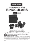
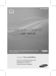
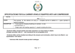
BY
Instruction Manual
4 BLADE ECOWIND
1)
INTRODUCTION:
Thank you for having chosen a MAX PROP® automatic feathering propeller for your vessel. This
instruction booklet is designed to answer all your questions on installation and use of the MAX
PROP®. Please read it carefully and verify the correct working of the propeller before installing it
on your boat.
2)
INSTALLATION:
The propeller is supplied already assembled for right or left rotation, according to the information
received at order and with the pitch required if discussed at the time of the order, and is therefore
ready to be fitted on the shaft. MAX PROP® parts are NOT interchangeable. Make sure, if you
receive more than one propeller, that you do not interchange parts. Please use Fig. 1.
x1
x2
x1
x3
x1
x1
x1
For Sail Drives
A) Fit the MAX PROP® onto the propeller shaft, like a fixed propeller, and be sure that the key
is proper dimension: A properly fit key has almost no clearance side to side but a very small
clearance on its upper surface. This clearance is to avoid the propeller being pushed off center by
a key which is too tall. If you are not sure, remove the key and slide the propeller onto the shaft
making a mark on the shaft where the front of the hub stops on the shaft. Re-insert the key and
slide the propeller back on to the shaft, if it slides up to your mark, it is fine. If not, you will need
to file down the sides or top of the key until the propeller slides completely onto the shaft.
B)
Tighten the nut and secure it in place using the two allen head screws.
Fig. 1.
Fill the prop with marine grease (supplied) using a grease fitting (supplied) inserted into the
grease holes on the side of the propeller marked “GREASE”. The MAX PROP® propeller works
properly only if the central body is completely filled with the correct grease. Verify that the grease
is oozing from the rotating joints between the central part and the hub, so that all of the moving
surfaces are perfectly oiled. The grease used must be a type of grease approved by MAX PROP®
so it will remain fluid after years of use and will not get too stiff in cold water.
2
1
3
GREASE
28
12
GREASE
30
10
30
10
28
12
GREASE
C)
30
10
28
12
5
6
GREASE
GREASE
28
12
7
30
10
28
12
30
10
GREASE
GREASE
28
12
28
12
9
8
30
10
D)
GREASE
30
10
30
10
28
12
GREASE
4
30
10
28
12
Move the blades into the feathered position, making sure that the rounded trailing edges of the
blades are aft as shown in Fig. 2.
Fig.2
E)
Before launching the boat, it is absolutely necessary to operate as follows:
• Hold the propeller shaft.
• Check that the blades of the propeller rotate freely from the forward to the reverse position
just by a light effort.
• In the feathered position the blades must be perfectly lined up and set like Fig. 1.
• Check that the propeller body is full of fluid marine grease.
• Make sure that the propeller is protected from galvanic corrosion by using the usual zinc
anodes on the propeller and the shaft.
3)
PITCH ADJUSTMENT:
MAX PROP® does not require a pitch setting. On this model the blades rotate automatically to the
desired pitch within an adjustable range, under any sailing conditions. This unique feature radically
improves both the vessel performance under power as well as the fuel consumption.
A) PITCH RANGE ADJUSTMENT IN FORWARD
MAX PROP® ECOWIND is delivered assembled with a pitch setting that we will call “basicpitch”. The basic pitch corresponds to the angle that the blades achieve in a non-load condition,
when the torque opposing propeller rotation is = 0. The best basic pitch is generally between 50º
- 60º (depending on diameter).
When you engage the engine in forward and the propeller starts rotating, the blades angle decreases
automatically, and sets itself at a pitch that corresponds to the load demand and keeps changing
according to changes of sailing conditions or throttle demand (against the wind or with, yacht
position to the waves, full or partial tanks, clean or dirty bottom, etc).
If at full throttle, the engines cannot achieve manufacture recommended maximum RPM or if the
engines reach max RPM too easily, the “basic-pitch” can be easily adjusted as follows, referring to
Fig. 3.
•
•
•
•
•
•
•
Remove the Set Screw from the hub reference hole in front of the regulation ring.
Pull the regulation ring towards the bow of the vessel and turn it to increase or decrease the
number according to your need.
Set the regulation ring so that the hub reference hole matches with the number on the ring
corresponding to the chosen number.
In order to make this operation easier we suggest screwing two screws into the threaded holes
on the regulation ring and using these screws for leverage.
Once you have aligned the reference to the selected number, make sure that you reset the ring
so it snaps back in place.
For security lock the regulation ring by placing a set screw into its hub reference hole in the
propeller hub.
Please note that for the MAX PROP® CLASSIC and FAST models, the same propeller can be
used as right or left rotation, however for the ECOWIND model the rotation must be chosen
upon order and cannot be changed.
Fig.3
B) PITCH REGULATION IN REVERSE
Only after finding the ideal setting in forward, should you adjust the pitch in reverse. The
ECOWIND is delivered with the most common insert already in place. If adjustment is required,
choose a different insert and fit it into the slot in the propeller (see Fig. 4). There are 7 inserts
available, and each one has a particular thickness. Fitting a different insert will produce a specific
pitch in reverse as noted in Fig. 3. Once the insert size is chosen remove the original by removing
the two screws and place the new size into the slot and lock it with the two scerws as in Fig. 4.
TYPE OF INSERT
7
6
5
4
3
2
1
DIFFERENCE IN BLADES ANGLE BETWEEN
FORWARD POSITION AND REVERSE POSITION
22
28
34
40
46
52
58
42
45
48
51
54
20
23
26
29
32
14
17
20
23
26
29
32
8
11
14
17
20
23
26
5
8
11
14
17
20
5
8
11
14
5
8
Fig. 4
Fig. 5
57
60
63
66
7
6
29
32
5
23
26
4
17
20
3
11
14
2
5
8
1
TYPE OF INSERT
BLADES ANGLE IN
REVERSE POSITION
BLADES ANGLE IN FORWARD POSITION
5)
PROPELLER USE:
The MAX PROP® ECOWIND works automatically. By putting the transmission in gear the
blades will engage in either forward or reverse (WARNING: do not change from forward to
reverse and vice versa when the engine is running at high RPM ) and feathers from forward
position when you turn off the engine and lock the shaft.
The best way to feather the propeller is:
• Power at 2 to 3 knots in forward.
• Kill the engine while still engaged in forward.
If your propeller has been greased properly it will feather in a fraction of a second as soon as
you stop the shaft from freewheeling. DO NOT kill the engine while in reverse. In this case the
blades will be in the reverse position and cannot feather. You can actually use this feature to drive
a shaft alternator.
Modern transmissions are either mechanical or hydraulic. With a mechanical transmission, the
best way to stop the shaft freewheeling is to engage the transmission in reverse (WARNING:
engage the reverse only after the engine has stopped completely). With a hydraulic transmission
you must shut off the engine while still engaged in forward. The remaining hydraulic pressure will
en effect lock the shaft for a few moments, enough for the MAX PROP® to feather.
6)
MAINTINANCE:
•
•
The propeller must always be completely filled with recommended grease, the propeller
should be greased at least once a year.
Make sure that you always keep the zinc anodes in good condition. They must be replaced at
least once a year, even if they still look ok. The propeller must be protected by a lot of zinc,
so also use a zinc on the shaft when possible. When replacing it make sure that you clean the
surfaces between the zinc and the propeller shaft in order to have a good electrical contact.
WARNING:
It is important to follow the instruction below carefully so as to avoid a shock load to the
gears on the blades and cone gear, that could be damaging to the teeth.
• When going from forward to reverse and the opposite, it is necessary to idle down and
shift at low RPM’s between gear, that could be damaging to the teeth.
7)
PROPELLER REMOVAL:
In order to remove the propeller you must first
remove the zinc and remove the nut. Next fit a long
armed gear puller over the front of the propeller as
show in Fig. 6. Tightening the center bolt of the
gear puller will release the MAX PROP® from the
propeller shaft.
If the bolt from the gear puller is not long enough
to contact the end of the propeller shaft inside
the MAX PROP® the MAX PROP® nut can be
loosened and left in place. In this scenario the bolt
from the puller will push against the back of the nut
to release the propeller from the shaft.
Fig.6
MAX PROP PATENTED PROPELLERS
PYI Inc., 12532 Beverly Park Rd., Lynnwood, WA 98087
Tel: 425-355-3669 Fax: 425-355-3661 [email protected] www.max-prop.com