1
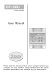
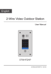
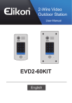
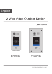
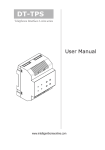
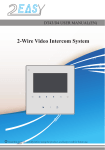
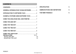
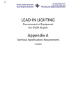
DPA-D2-BDU
BDU
amplifer
User Manual
2-Wire System
Bus Amplifier
Model: BDU
Bus-IN
Tx/Rx
Bus-OUT
In-Use
PA
PB
NoRoute Amp-ON
Please read this manual carefully before using the product you
purchase, and keep it well for future use.We reserve the right to
modify the specification in this manual at any time without notice.
1.About BDU Unit
Discription:
The BDU unit is bus amplifier unit and networking component designed for
2-wire system.
2. Terminal Description
DIP
6 5 4 3 2 1
Bus Amplifier
Model: BDU
INDICATORS
Bus-IN
Tx/Rx
Bus-OUT
In-Use
PA
PB
BUTTONS
NoRoute Amp-ON
OUT
IN
DS
IN
DIP Setting:
Bit-1 to Bit-2 are used to BDU working modes setting.
Bit-3 to Bit-5 are used to address settings.
Bit-6 is used to video Impendence match.
-1-
ON
2-Wire System
ON
6 5 4 3 2 1
The detail settings of DIP are as follows:
Bit
Bit State
1 2 3 4 5 6
Set to the Repeater mode.
1 2 3 4 5 6
Set to the Router mode.
1 2 3 4 5 6
Set to the Gateway mode.
1 2 3 4 5 6
Reserved.
1 2 3 4 5 6
Set to the first BDU
1 2 3 4 5 6
Set to the second BDU
1 2 3 4 5 6
Set to the third BDU
1 2 3 4 5 6
Set to the fourth BDU
1 2 3 4 5 6
Set to the fifth BDU
1 2 3 4 5 6
Set to the sixth BDU
1 2 3 4 5 6
Set to the seventh BDU
1 2 3 4 5 6
Set to the eighth BDU
1 2 3 4 5 6
Used to video Impendence match, set to ON.
ON
Bit-1~Bit-2
ON
ON
ON
ON
ON
ON
Bit-3~Bit-5
ON
ON
ON
ON
ON
Bit-6
Description
ON
-2-
INDICATORS:
1.Bus-IN: Always on when connect to net.
2.Bus-OUT: Always on when connect to monitor.
3.Tx/Rx: Flashes when communicating.
4.In-Use: Always off when in standby mode;
In working state, flashes when in automatic gain mode;
In working state, always on when in fixed gain mode.
BUTTONS:
1.PA: In working mode, each time you press "PA" button to reduce the
video gear a grade(no longer reduce when the gear is 1). Not
saved. Specific gears are indicated by 4 indicators.
2.PB: In working mode, each time you press "PB" button to increase the
video gear a grade(no longer reduce when the gear is 6). Not
saved. Specific gears are indicated by 4 indicators.
3.NoRoute: In working mode, press "NoRoute" button, Use 4 LEDS to
indicate current gear gain;
In working mode, press and hold "NoRoute" button for 3
seconds to switch the working mode (In-User will indicate); If
"PA" and "PB" button have been pressed, that is, have made
the adjustment of video amplitude, the current adjusted gear
of video gain will be saved;
4.Amp-ON: In standby mode, press "Amp-ON" button, it will be forced into
working mode (audio/video power supply open).
In working mode, press "Amp-ON" button, it will be forced into
standby mode (audio/video power supply closed).
-3-
Video Gain Gears
Gear gain indication: All indicators off, then use Bus-IN, Bus-OUT, Tx / Rx
indicators to shown the current video gain gears.
Gear 1
Gear 2
Gear 3
Gear 4
Gear 5
Gear 6
Bus-IN
Bus-OUT
Tx/Rx
* NOTE:
:It shows that the indicator ON;
:It shows that the indicator OFF.
3. Unit Mounting
Step1: Mount the din rail to
the wall with screws ;
Din rail
Step2: Pull down the
mounting buckle,then hang
the unit on din rail.
Din rail
Mounting Buckle
-4-
4. Working Mode Wiring.
4.1 Repeater Mode (Line amplifier):BDU can extend the distance of
DT system when works in repeater mode. As follows:
Max 140m from the first door station to BDU
Max 140m from the last indoor monitor to BDU
B
P C6
Repeater Mode
P C6
B
Wiring diagram:
ON
AC~
1 2 3 4 5 6
BDU
PC6
BUS(IM) BUS(DS)
OUT
DS
IN
IN
AC~
PC6
BUS(IM) BUS(DS)
-5-
BDU
4.2 Router Mode: Use 8 BDUs at most in this mode.
4A
B
PC6
4A
4A
B
PC6
PC6
1
4
2
3
5
6
7
8
9
*
0
#
B
-6-
BDU
Wiring diagram:
AC~
AC~
PC6
PC6
BUS(IM) BUS(DS)
BUS(IM) BUS(DS)
ON
ON
AC~
1 2 3 4 5 6
BDU
OUT
DS
1 2 3 4 5 6
BDU
IN
IN
OUT
DS
PC6
IN
IN
BUS(IM) BUS(DS)
1
4
-7-
2
3
5
6
7
8
9
*
0
#
4.3 Gateway Mode: : In this mode, the first door station can call all
the monitors and can connect 7 BDUs at most.
4A
4A
4A
4A
PC6
B
B
PC6
PC6
1
4
2
3
5
6
7
8
9
*
0
#
-8-
4A
DBC4A
B
BDU
Wiring diagram:
AC~
AC~
PC6
PC6
BUS(IM) BUS(DS)
BUS(IM) BUS(DS)
ON
ON
AC~
1 2 3 4 5 6
BDU
OUT
DS
1 2 3 4 5 6
BDU
IN
IN
OUT
DS
PC6
IN
IN
BUS(IM) BUS(DS)
1
4
-9-
2
3
5
6
7
8
9
*
0
#
5. Specification
•• Power Supply : DC24V;
•• Power consumption: Standby 13.5mA; Working 156mA;
•• Working Temperature: -150C~+550C;
•• Wiring:
2 wire,non-polarity;
•• Dimension: 90(H)×72(W)×60(D)mm.
-10-
The design and specifications can be changed without notice to the user. Right to interpret
and copyright of this manual are preserved.