1
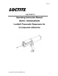
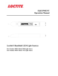
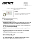
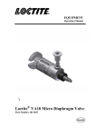
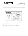
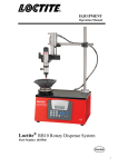
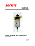
EQUIPMENT Operation Manual Loctite LED Flood System Part Numbers: 1167582 1167593 1167589 375 nm Array 405 nm Array Indigo™ Array 1 1 Please Observe the Following 1.1 Emphasized Sections WARNING! Refers to safety regulations and requires measures to protect the operator and others from injury or danger to life. Caution! Emphasizes what must be done or avoided so that the unit or other property is not damaged. Notice: Gives recommendations for better handling of the unit during operation or adjustment, as well as for service activities. 1.2 Items Supplied 1 LED Curing Array 1 Users Manual 1.3 Additional Items Required 1 LED power cable # 1333333 1 LED Flood System Power Supply # 1359255 1.3 For Your Safety For safe and successful operation of the unit, read these instructions completely. If the instructions are not observed, the manufacturer can assume no responsibility. Be sure to retain this manual for future reference. WARNING! Do not look directly into the LED/reflector array. WARNING! Damage to the power cord, power supply housing or LED housing can result in contact with live electrical parts. Check the power cord and housings before each use. If the power cord or units are damaged, do not operate. WARNING! The unit must be repaired only by a Loctite® authorized service technician. Caution! The light from the unit can heat surfaces it is directed towards. Care must be taken to determine the proper offset distance and exposure time. Caution! Do not block the fan or prevent air from passing through the heat sink. Allow at least six inches from the fan and heat sink to any obstructions. 1.4 Field of Application, (Intended Usage) The Loctite LED Flood Systems, 375, 405 and Indigo™ are designed to be used with Loctite® UV Curing products, UV/VIS curing products and Indigo products, respectively. 2 2 Description 2.1 Theory of Operation The LED flood array consists of 144 reflectorized LED’s that produce an effective curing area of approximately 100mm x 100mm. The housings are designed to be stackable side by side without creating “dark”spaces between units. The controller/power supply, (not included), provides electrical power to the LED’s through the connecting cable, (not included). Indicator lights located on the front panel of the power supply provide visual confirmation that the LED’s are in or out of their acceptable range. In the event of temperature fault the power supply will automatically shut down to protect the LED array. When the cure cycle is initiated, light is immediately irradiated at or near maximum intensity from the LED’s. The LED arrays are available in three different wavelengths to match the absorbing properties of the Loctite® adhesive, and thereby maximize the efficiency of the curing process. The wavelengths available are: 375 nm (Part # 1167582) Intended for use with Loctite® UV curing products 405 nm (Part # 1167593) Intended for use with Loctite® UV/VIS curing products Indigo (Part # 1167589) Intended for use with Loctite® Indigo™ product line The curing process begins when the adhesive is placed under the LED’s. The two primary variables that control the curing process are the time of exposure and the strength of the light, (irradiance). For a given irradiance, the exposure time required to fully cure the adhesive depends primarily on the properties of the adhesive and the optical properties of the substrate that the light is transmitted through. 2.2 Product Features Typical Irradiance: o LED Flood Array 375 nm: 300 mW/cm2 o LED Flood Array 405 nm: 600 mW/cm2 o LED Indigo® wavelength: 600 mW/cm2 Instant On/Off (no warm-up time required like traditional arc lamp systems). 3 Operating the Unit 3.1 Electrical Connections (With No AC Power To Unit) - Plug one end of the power cable into the 15 pin D-sub connector located on the rear panel of the LED housing. Plug the opposite end into the 15 pin D-sub connector located on the rear panel of the power supply. Make sure that the connections at both ends are secure. - For manual operation, plug the footswitch into the 9 pin D-sub connector marked “Start Signal Input and Fault Output”located on the rear panel of the power supply. 3 - For automated control, connect external PLC to pins one and nine of the “Start Signal Input and Fault Output”. When in the manual operating mode the LED array will remain on as long as continuity is maintained across pins one and nine. When in timed mode continuity must be made across pins 1 and 9 only momentarily for the LED array to come on for the amount of time selected on the front panel timer. 3.2 Curing Procedure - Having determined the irradiance necessary to cure the adhesive, fixture the reflector housing over the work surface at the proper height. The M5 threaded inserts located in the top of the reflector housing are intended for this purpose. - When the cure cycle is initiated from the controller, the LED’s will light immediately. - Place the part/adhesive assembly under the reflector housing so that the center of the bond area is under the center of the housing for the required exposure period. If the unit is mounted over a conveyor, the parts must be passed under the center of the reflector housing for the best results. 4 Maintenance 4.1 Protective Glass Notice: It is recommended that the protective glass in the reflector housing be regularly inspected for cleanliness. Contaminants will adversely affect the curing process by reducing the transmission of visible light to the adhesive. Remove any contaminants by carefully wiping the glass surface with a soft, clean cloth and isopropyl alcohol. 5 Trouble Shooting Condition None of the LED’s light when the cycle is initiated. The LED’s go out after operating for a short time. Some of the LED’s do not light. The product takes increasingly longer to cure. Possible Cause Damaged or improperly installed power cable. Thermal overload. Correction Check both ends of cable are secure. Check LED array cooling fan operation. Damaged LED power cable. Replace cable. Contamination on Clean off glass with clean soft protective glass. cloth and isopropyl alcohol. 4 Mounting Hole Locations UVA LED Flood System Item # 1167582 LED Flood System S/N: XXXXX FOR SPARE PARTS, MANUALS, REPAIRS, OR TECHNICAL ASSISTANCE: Visit us at equipment.loctite.com or call Henkel Corp. at: USA - (1) 860-571-5174 Germany - (49) 89-9268-0 Singapore - (65) 6266-0100 Label P/N: 988341 RoHS Compliant Label P/N 8900605 Important! Do not restrict cooling air. Allow at least six inches clearance from exhaust fan port and heat sink intake. 5 WARRANTY Henkel expressly warrants that all products referred to in this Instruction Manual for the LED Flood Systems (hereafter called “Products”) shall be free from defects in materials and workmanship. Liability for Henkel shall be limited, as its option, to replacing those Products which are shown to be defective in either materials or workmanship or to credit the purchaser the amount of the purchase price thereof (plus freight and insurance charges paid therefore by the user). The purchaser’s sole and exclusive remedy for breach of warranty shall be such replacement or credit. A claim of defect in materials or workmanship in any Products shall be allowed only when it is submitted in writing within one month after discovery of the defect or after the time the defect should reasonably have been discovered and in any event, within (12) months after the delivery of the Products to the purchaser. This warranty does not apply to perishable items, such as fuses, filters, lights, etc. No such claim shall be allowed in respect of products which have been neglected or improperly stored, transported, handled, installed, connected, operated, used or maintained. In the event of unauthorized modification of the Products including, where products, parts or attachments for use in connection with the Products are available from Henkel, the use of products, parts or attachments which are not manufactured by Henkel, no claim shall be allowed. No Products shall be returned to Henkel for any reason without prior written approval from Henkel. Products shall be returned freight prepaid, in accordance with instructions from Henkel. NO WARRANTY IS EXTENDED TO ANY EQUIPMENT WHICH HAS BEEN ALTERED, MISUSED, NEGLECTED, OR DAMAGED BY ACCIDENT. EXCEPT FOR THE EXPRESS WARRANTY CONTAINED IN THIS SECTION, HENKEL MAKES NO WARRANTY OF ANY KIND WHATSOEVER, EXPRESS OR IMPLIED, WITH RESPECT TO THE PRODUCTS. ALL WARRANTIES OF MERCHANTABILITY, FITNESS FOR A PARTICULAR PURPOSE, AND OTHER WARRANTIES OF WHATEVER KIND (INCLUDING AGAINST PATENT OR TRADEMARK INFRINGEMENT) ARE HEREBY DISCLAIMED BY HENKEL AND WAIVED BY THE PURCHASER. THIS SECTION SETS FORTH EXCLUSIVELY ALL OF LIABILITY FOR HENKEL TO THE PURCHASER IN CONTRACT, IN TORT OR OTHERWISE IN THE EVENT OF DEFECTIVE PRODUCTS. WITHOUT LIMITATION OF THE FOREGOING, TO THE FULLEST EXTENT POSSIBLE UNDER APPLICABLE LAWS, HENKEL EXPRESSLY DISCLAIMS ANY LIABILITY WHATSOEVER FOR ANY DAMAGES INCURRED DIRECTLY OR INDIRECTLY IN CONNECTION WITH THE SALE OR USE OF, OR OTHERWISE IN CONNECTION WITH, THE PRODUCTS, INCLUDING, WITHOUT LIMITATION, LOSS OF PROFITS AND SPECIAL, INDIRECT OR CONSEQUENTIAL DAMAGES, WHETHER CAUSED BY NEGLIGENCE FROM HENKEL OR OTHERWISE. 6 Henkel Corporation One Henkel Way Rocky Hill, CT 06067-3910 Henkel Canada Corporation 2515 Meadowpine Boulevard Mississauga, Ontario L5N 6C3 Canada Henkel Capital, S.A. de C.V. Calzada de la Viga s/n Fracc. Los Laureles Loc. Tulpetlac, C.P. 55090 Ecatepac de Morelos, Edo. de México Henkel Corporation Automotive / Metals HQ 32100 Stephenson Hwy. Madison Heights, MI 48071 Henkel Ltda. Rua Karl Huller, 136 –Jd. Canhema 09941-410 Diadema/SP, Brazil www.loctite.com Loctite is a trademark of Henkel Corporation, U.S.A. © Copyright 2004. Henkel Corporation All rights reserved. Data in this operation manual is subject to change without notice. Manual P/N: 8901873, Rev C, Date: 08/07/2013 7