1
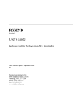
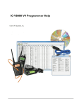
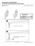
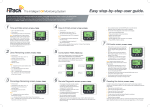
RACES portable communications box
Page 1 of 7
Ecole FrancoAméricaine NY
Looking for Dynamic DNS?
Free DNS Hosting
Programme bilingue et biculturel
Maternelle jusqu'à la terminale
www.fasny.org
Need Dynamic DNS Facts? We Can Help.
mega-search.tv/DynamicDNS
Advanced web-based DNS services. Mail
services, web, and dynamic DNS
www.dnspark.com
Notes on building a portable self-powered
communications station suitable for RACES,
ARES, remote station, or general QRP use
n2mpt !at! losdos.dyndns.org
version 1.4 @ 29dec2006 -- still a work in progress(tm)
(Note: all images here are clickable!)
Introduction
For a while now I've wanted to build a portable station for remote or emergency communications use.
I had the following design requirements in mind:
http://losdos.dyndns.org:8080/public/ham/RACES-box.html
7/17/2008
RACES portable communications box
1.
2.
3.
4.
5.
6.
7.
8.
Page 2 of 7
ability to operate from AC mains, internal battery, or external DC power.
provide everything needed for emergency communications (EMCOMM) in one container.
capable of providing a reasonable amount of battery power (~24hrs EMCOMM).
ability to monitor battery state of charge during operation and when recharging.
no fuses.
modular design which could later incorporate additional/different radios or other features.
support for power receptacles for other equipment, e.g. GPS, APRS, cell phone charger, etc.
weatherproof to the extent that it could be transported in light rain in the back of a pickup truck.
New Pictures: HF Radio added!!!
I've added an Icom 703+ HF/6m rig to the setup -- pictures attached below. As a QRP rig, the 703+ has an
integral autotuner, 10W output, and minimal power consumption on receive. This makes it perfect for this
application. The depth of the 703+ required swapping the V8000 to the right, with the 703+ going in it's place.
This is due to the fact that there is more headroom available over the power supply than over the batteries.
DC Power: Battery
Since a primary requirement was battery powered operation -- and batteries are heavy and consume lots of space - a good place to begin was to determine how much battery capacity would be required. First, I had to figure out
what the load on the battery would be. The Icom V8000 2M mobile which I was planning on using has, according
to the Icom manual, the following current draw characteristics:
300mA standby.
1.0A
RX, max audio output.
15A
TX, max 75W RF output.
Well, that's only partially helpful; while the standby number is somewhat useful, the other two are not. First, I
don't plan on having the volume knob cranked all the way up during operation; and second, I tend to think that
with a reasonable antenna it would not be necessary to use the highest RF power output level. The V8000 has
four power level settings; per the manual they are nominally 5W, 10W, 25W, and 75W. In reality these are
somewhat conservative numbers, especially at the lower power levels. With a 13.8Vdc input, my V8000 outputs
7.5W, 13W, 32W, and 77W respectively into a 50ohm dummy load. Even when powered with straight 12.00Vdc,
the radio nearly meets its advertised rated output at all but the highest power level. To obtain better granularity I
measured the current draw under various conditions:
270mA standby, no microphone att'd.
300mA standby, microphone att'd.
300mA scanning, ~10 frequencies.
310mA RX, normal audio output.
4.7A
TX, "low" 5W setting.
7.2A
TX, "mid-low" 10W setting.
~10.0A TX, "mid" 25W setting.
http://losdos.dyndns.org:8080/public/ham/RACES-box.html
7/17/2008
RACES portable communications box
~15.0A
Page 3 of 7
TX, "high" 75W RF setting.
(aside: The last two values are approximations, as my multimeter only measures current to 10A. Lacking an
external current shunt to do the measurement, I feared that the higher power settings would pop the the
multimeter's internal 10A "fast-blow" fuse -- a type and rating of fuse for which I don't have a spare handy.
Should you have actual measurements for the V8000's input current draw at the "mid" and "high" settings, please
let me know via the email address in the header. This data will provide me with more accurate operating time
calculations in the following section.)
Using a fairly aggressive 70/20/10 duty cycle (70% standby, 20% receive, and 10% transmit at the 25W setting)
yields the following:
.7 x 0.3A = .21 (42 minutes standby every hour)
.2 x 0.3A = .06 (12 minutes of RX every hour)
.1 x 10A = 1 (6 minutes of TX every hour, at 25W output)
Summing these results in a 1.27A average current draw. To operate at this duty cycle for an hour would require
1.27AH of battery capacity. And, to operate for 24 hours would require approximately 30AH. Those of you
familiar with current sealed lead-acid battery technology know that 30AH is getting into "it's getting tough to lug
around" territory.
From a practical standpoint, I had three constraints. First, the battery had to be small enough to fit into a modest
enclosure; second, it had to be light enough to be carried around; and third, it had to be reasonably priced. I
discovered that if I relaxed my operating time requirement just slightly I could concurrently meet all of my
technical criteria and my "it should be low cost" goal. I chose to use a pair of 12V 12AH SLA/AGM batteries,
wired in parallel of course; this would provide a total of 24AH of capacity. Moreover, 12V 12AH SLA/AGM
batteries are widely used in UPS applications, meaning that the economies of scale were on my side. In fact, one
of the most popular sizes of UPS (~1000VA range) is configured to use precisely the same setup -- a pair of 12V
12AH batteries such as this APC model "RBC6" 12V 12AH x 2 battery pack. High quality batteries of this type
at very attractive pricing could easily be found by searching on google and Ebay for RBC6. This battery pack was
to be the starting point for my portable box. The RBC6 weighs in at 17 lbs [7.7 Kg].
AC Power: Samlex 1223
I had a spare Samlex 1223 switch mode power supply which simultaneously met two criteria: it was very light
(about 3.5 lbs [1.6Kg]) and it had more than sufficient current output capacity (23A continuous) to supply the
radio at maximum RF output. The headroom also would power some 12Vdc accessories as well. More details on
this excellent AC power supply are in the user manual.
Enclosure
I looked at various types of enclosures -- surplus military ammo boxes, hunting boxes, commercial equipment
cases, and so forth. Ultimately I decided on a "Sportsman's Utility Dry Box" manufactured by MTM Case-Gard.
The model SPUD7 I chose features a weatherproof, rubber-gasketed top lid along with heavy thickness sidewalls
and bottom. In addition, the hinged top (which is also removable) has a secondary compartment suited for
carrying miscellaneous small items. The box also comes with an accessory tray; see the end of this writeup for
what I did with it. The only issue was that internally the box is smooth-walled. That is, there are no ribs or
flanges suited for attaching mounting brackets to. So I would have to carefully consider methods to mount the
brackets necessary to hold the batteries and radio(s) without impacting weather resistance. There was no getting
around drilling mounting holes in the box sides or bottom, but I believed that with a little care (and perhaps some
http://losdos.dyndns.org:8080/public/ham/RACES-box.html
7/17/2008
RACES portable communications box
Page 4 of 7
gasketing) I could maintain integrity against water ingress. Incidentally, I had made the explicit decision to mount
all connectors inside the box. That is, the connectors for AC and DC power, antenna, and so forth would be inside
the watertight compartment -- which, in addition to helping keep the weather out, would also protect them from
any mechanical damage.
Battery and Power Supply Mounting
The battery pack and power supply fit nicely together and would be mounted to the bottom of the enclosure. To
do so I thought of using a "carrier" panel which would mount the two items and prevent the heavy battery pack
from bouncing around. Both the battery pack and the power supply would be held to the panel via web strapping
and simple friction locks. The panel would then be screwed to the bottom of the box. Optimally the carrier panel
would be thin, strong, and easy to machine during construction. My plan to use a nice, 1/2" thick Delrin panel
collapsed when my wife discovered me in the kitchen measuring her new cutting board. Instead, I substituted a
piece of 1/2" thick plywood -- I figured that it would allow me to work out the design details and then I could
make another foray into the kitchen. Using my router, I plowed a recessed area to hold the battery pack, and
additionally made cutouts for the web strapping which would be used to secure the battery pack and power
supply. I then drilled holes which would accept T-nuts; these fit flush with the top surface of the plywood panel
and remove the need for hex nuts and washers inside the box. A total of 4 marine-grade stainless 1/4" [6mm] dia
screws secure the panel to the bottom of the box. Under the screw heads are stainless fender washers, which are
large diameter to spread the load and prevent pull-through of the screws. In addition, small flat rubber washers
are used to ensure that water can not get in through the screw holes. I even tested this out by putting the box in
the bathtub overnight, sans any radio equipment of course. Weighed down with a few bricks, the box sat
overnight in 2" [50mm] of water without a drop getting inside. Once mounted into the box, the panel securely
held the battery pack and the power supply and maintained water tightness. Time to move on to installing the rest
of the gear.
Radio Mounting
I knew ahead of time that somewhere down the road I'd put a different (or additional) radio into the box. Hence,
the mounting arrangement had to be simple and allow for flexibility. So I applied the KISS principle and used a
length of inexpensive aluminum "U" channel to create a mounting bar for radio equipment. Each side of the "U"
channel measured 1/2" [12.5mm]. Stainless bolts and nuts in conjunction with rubber washers were again
employed to attach the mounting bar to the sidewall of the box. Since the box would generally be used while on
it's side, the mounting bar now determined which way was up. The Icom-supplied mobile bracket was attached to
the radio mounting bar via screws and nuts. The stiffness of the aluminum "U" channel provided a secure and
versatile platform for mounting this or other radios. This part was relatively easy; the tough part of the project
was coming up.
Switch, Instrumentation, and Connector Mounting
http://losdos.dyndns.org:8080/public/ham/RACES-box.html
7/17/2008
RACES portable communications box
Page 5 of 7
As you can see from the requirements listed in the introduction, there were a number of necessary components
that were not yet accounted for. For example, I needed to implement features such as overcurrent protection,
selection of power supply, battery monitoring, and accessory power outlets. This would require mounting circuit
breakers, switches, a panel meter, and a number of connectors. I started off by gathering up all of the piece parts
and laying them out in the box, placing each where wiring would be optimal (i.e., shortest path). I went through
quite a few iterations. The problem was that I had too much "stuff", and mounting all of it was looking
problematic. The various component shapes and sizes could make fabrication of several brackets necessary. I
considered several options, but settled on making a single large bracket that would mount all of the switches,
instrumentation, and connectors. This mounting bracket would be located on the box wall opposite the radio, and
thus on the bottom when the box was on it's side in the normal operating position.
Several back-of-the-napkin sketches were made of the layout. As there were a variety of mounting hole shapes
and sizes, it was clear I was going to be spending quite some time at my drill press and with a file. The round
holes aren't so bad but the square cutouts required for the switches and panel meter would require a lot of finesse.
Ultimately I decided to call in air support. A friend of mine runs a small sheet metal fabrication business. He
does the design work in PTC Pro/Engineer, a high end CAD tool, and then exports the design data to a CNC
automated turret punch machine. The CNC punch machine, driven by output from the CAD tool, makes quick
work of knocking precision holes in a flat sheet blank. Subsequently, the flat blank is formed into a right angle on
a bending machine called a brake. This was exactly what I needed. We spent a few hours playing with the design
in Pro/Engineer, rotating the 3D model on the screen and working on ensuring proper fit. Then it was off to the
punching and brake machines. And so for the cost of the aluminum sheet material and some pizza, he fabricated
my multiple hole mounting bracket plus a spare. The result was a professional component arrangement, one
which certainly functions and looks worlds better than what I could have done with my drill press and vise.
The completed bracket mounts the following, from left to right:
AC power supply output 20A breaker
Battery pack 20A breaker.
DC source select rocker switch, DPDT center off type.
Charging circuit 4A breaker.
Digital Panel Meter (DPM).
Toggle switch, SPDT X 2
(#1 selects power supply or battery pack voltage; #2 DPM backlight).
Andersen PowerPole panel mount gang-of-four connector.
BNC connector X 2, panel mount radio RF outputs (currently one spare)
AC power input receptacle, IEC 320 type with integral EMI filter
Here is a PDF format keynote drawing of the component mounting bracket.
Wiring, Breakers, and Panel Meter
All of the various components fit perfectly into the bracket and the process of wiring started. I planned to have
the three subsections (power supply/battery pack panel, radio mounting bracket, switch/instrumentation/connector
bracket) easily separable. I employed Andersen PowerPole connectors (got them from PowerWerx, also available
from West Mountain Radio) and 12 AWG wire to interconnect the power source and loads, including the external
http://losdos.dyndns.org:8080/public/ham/RACES-box.html
7/17/2008
RACES portable communications box
Page 6 of 7
connectors. These clever, asexual connectors are easy to assemble, handle up to 45A, and when paired they
prevent reverse polarity mating accidents. Note that there is a PowerPole RED/BLACK orientation convention in
widespread use within the amateur radio community, and adherence to proper crimping (see also here) is
essential. For connection to external loads, I used an Andersen panel mount "gang of four" housing. In addition, I
made up a short cable which on one end had PowerPole connectors and at the other end a cigarette lighter socket.
This way, I could power anything that had a automotive cigarette lighter plug on it.
Under normal operation, the AC power supply is selected to supply current for the radio. In the event that AC
power fails, or for remote operation, the rocker switch is simply toggled to select the battery pack. There is a
center-off position to the rocker switch which disconnects all supplies from all the loads; this insures that the
battery isn't inadvertently drained during storage. I also needed a busbar for connecting all of the ground wires to;
I used a Square-D load center grounding bar that I picked up at Home Depot.
In my requirements I noted that I wasn't going to use fuses. My take is that no matter what fuse style you pick, the
specific type you need to replace a blown one is never handy. This would be very problematic in the field or in an
emergency situation. Clearly overcurrent protection was needed, so I elected to use panel mount DC breakers.
These are widely available at marine stores in my area. The magnetically actuated breakers provide an on/off
switch function along with overcurrent protection. In my circuit, there is a pair of 20A breakers, one each
protecting the AC power supply and the battery pack. In addition, a third 4A breaker protects the battery charging
circuit.
Some time ago I picked up a pair of digital panel meters (DPM) at a computer show. I didn't actually have a use
for them at the time, and so they sat in a box for several years before this project came along. At first, I hadn't
thought of using a DPM, in fact I was preparing to build up a simple LED meter using the National
Semiconductor LM3914 device. But while I was looking through my junk boxes for some other parts, I rediscovered the DPMs that I had stashed long ago. After a little bit of datasheet inspection, the Lascar model
DMM939 seemed to be perfectly suited for my task. It is an autoranging type, has an internal isolated power
supply, and requires a minimum of connections to measure DC voltage. Of the 16 pins on the back of the DPM, I
only had to short two together, connect one to ground, connect one to the 12V supply, and then two others would
provide the measurement input. These last two I wired through a SPDT switch so I could select measurement of
the AC power supply output or the battery pack voltage. With the DPM in place, I could monitor battery voltage
either during operation or when charging was underway.
---> Link to basic wiring diagram: PDF Schematic
Final Touches
The finished box meets all of the requirements that I thought of before starting the project. Packed up, the readyto-roll box weighs in at ~26lbs [11.8Kg]. I have a few other details to work out, including the addition of a fitted
storage bin to the inside of the box. Incidentally, this is why the connector bracket is set back fairly deep. More
on that later.
Update, accessory storage tray complete
http://losdos.dyndns.org:8080/public/ham/RACES-box.html
7/17/2008
RACES portable communications box
Page 7 of 7
As noted above, the setback of the brackets was intentionally deep, so that the accessory tray could be utilized
with the radio mounted. I used a jigsaw to cut a square recess out of the tray, which allows the radio to poke
through. As usual, pictures are worth a thousand words...
Here's what the box looks like in the shack -- operating as a 2M base rig and connected to a Diamond X50 atop
the house, but ready to go at a moments notice. ps: If the display in the pictures looks a little hokey, it's because
the unit was scanning when I snapped the photos.
ps1: Safety first! If you are unfamiliar with high current DC circuits or high voltage AC circuits then do not
attempt these types of projects.
ps2: original link, in case you print this out and want to come back here:
http://losdos.dyndns.org:8080/public/ham/RACES-box.html
ps3: If you have any comments, corrections, clarifications, suggestions, hate mail, success stories, etc regarding
this writeup please let me know at the address in the header.
ps4: version history
1.0 10mar2005 -- initial release.
1.1 15feb2005 -- lots of edits to clarify things and fix wording.
1.2 10jun2005 -- added accessory tray insert pics.
1.3 22jul2005 -- added schematic PDF link.
1.4 29dec2006 -- added pictures with the 703+ mounted.
ps5: useful related links: http://home.comcast.net/~buck0/combox.htm /
http://webpages.charter.net/n3ljs/jumpbox.htm
http://losdos.dyndns.org:8080/public/ham/RACES-box.html
7/17/2008