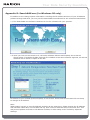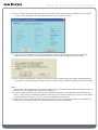
1
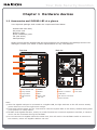
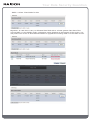
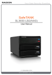
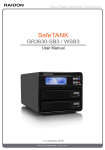
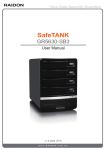
Your Data Security Guardian
SafeTANK
SL5640-LB2
User’s Guide
V1.0 (February 2012)
Your Data Security Guardian
Table of Contents
Chapter 1 Hardware devices
1.1
1.2
1.3
Accessories and SL5640-LB2 at a glance
LCD message and light indicators
Hardware installation
Chapter 2 Initial setup
Chapter 3 Introduction to user interface
3.1 Structure of user interface
3.2 Login
3.3 Systems management
3.3.1 Disk / RAID setup
3.3.1.1 Disk and disk space
3.3.1.2 Information: display hard disk relevant information
3.3.2 Device name
3.3.3 Setup date and time
3.3.4 Language
3.3.5 Network setup
3.3.6 Buzzer / fan setup
3.3.7 Power management
3.3.8 Event log
3.3.9 System settings backup and master reset
3.3.10 Firmware update
3.3.11 Systems information
3.3.12 iSCSI
3.4 Permission management
3.4.1 User
3.4.2 Group
3.4.3 Public folder
3.4.4 Window AD
3.5 Permission management
3.5.1 Apple network
3.5.2 Linux NFS service
3.5.3 FTP
3.5.4 SSH
3.6 Application services
3.6.1 Path for download
3.6.2 File manager
3.6.3 Multimedia service
3.6.4 Cloud Server (SyncBox)
3.7 External device
3.7.1 USB drive
3.7.2 USB printer
Your Data Security Guardian
Chapter 4 Appendices
Appendix
Appendix
Appendix
Appendix
A: BT downloads
B: AjaXplorer Windows Explorer
C: cloud server Syncbox
D: SearchNAS.exe (for Windows OS only)
Your Data Security Guardian
Chapter 1 Hardware devices
1.1 Accessories and SL5640-LB2 at a glance
Your shipment package shall contain the components listed below:
•SL5640-LB2 main body
•AC power cord
•Network cable
•Quick installation guide
•CD (this Guide)
•Parts package
Please ensure that the SL5640-LB2 and its accessories are contained in the package and are not
damaged. Contact your dealer or sales representative for any uncertainties.
Front view
Back view
Drive Position(1)
Drive Position(2)
Reset
Drive Position(3)
USB
Drive Position(4)
LAN 1
LAN 2
Enter
Esc
HDD Status LED
DOWN
Fan
RJ45 Port
Tray Handle
ENTER
Reset to Default
Lock Hole
Tray Button
ESC
USB Port
LCD Monitor
Power LED
AC Power Connector
UP
Fail LED
Power Switch
Note:
※ After the Gigabit LAN port is connected to a Gigabit LAN, the light indicator to the left turns a steady
green while the one to the right turns orange.
※ Press and hold the Reset key for 5 seconds to reset the system back to the factory default setting after
your system is in ready status.
※ SL5640 dual Gigabit LAN Port, mainly as a Hub functions as a network expansion interface, a network
device can be connected through the SL5640.
※ Do not connect two Gigabit LAN at the same time, this will result in the SL5640 unable to connect to
the network, select one Gigabit LAN Port can use.
Your Data Security Guardian
1.2 LCD message and light indicators
1. SL5640 LCD key and LCD messages
>LCD key
Left/right: toggle switch between left and right
ESC: back to last page
Enter: OK and go to the next page
>LCD message
LCD message tree and description
Level 1
Level 1
Level 1
1-1
XXX.XXX.XXX.XXX
PORT:80
1-2
2-1
2-1-1
Info rmation
RAID Info
RAID Info
(Enter or Esc)
(E n t e r o r E s c )
XXXXXXXXXXXXX
2-2
2-2-1
IP Info
Network Info
(E n t e r o r E s c )
XXXXXXXXXXXXX
2-3
2-3-1
Disk Info
Disk Info
(E n t e r o r E s c )
XXXXXXXXXXXXX
LCD message tree overview
1-1 Main screen: display IP address
1-2 System information
2-1 RAID message
2-1-1 Display information on existing disk arrays
2-2 Network information
2-2-1 IP address of DHCP server
2-3 Disk information
2-3-1 The underlying message of the hard disk
Your Data Security Guardian
2. Light indicator
SL5640-LB2
Status
Light indicator
Power on/standby
Power light turns blue
Data access
HDD light flashes blue
Fan failure
Failure light turns red
Overheat (System temperature above 55℃ or
Failure light turns red
CPU temperature above 85℃)
Hard disk failure
HDD light turns red
Rebuilding
HDD light flashes blue
1.3 Hardware installation
Install your SL5640 product by following the steps described below:
Step 1 Remove your product from the shipping package. (Please ensure that the SL5640-LB2
and its accessories are in the package and not damaged. Contact your dealer or sales
representative for any uncertainties.)
Step 2 Place your product on a flat and stable surface. Make sure that the ventilation fan is not
blocked and adequate clearance is kept around your product. (Please keep your product
away from water or any environment that can damage the product.)
Your Data Security Guardian
Step 3 Remove the tray and install the hard disk in it. Make sure that your hard disk is locked
with screws to the tray to avoid any damage to the hard disk caused by unexpected
movements.
Step 4 Insert the tray back into place and lock it firmly at the proper location.
Step 5 Connect your product to a Gigabit LAN through the Gigabit LAN port. Connect the power
cord.
Step 6 Power on your product for the required setup and application.
Step 7 See Chapter 3 on setting up your product for the relevant management interface.
Chapter 2 Initial setup
Your SL5640 product employs a GUI for system management and setup. It takes about 1~2 minutes for
your SL5640 to start up. Your SL5640 cannot be discovered by your system before it has been started.
Step 1: Open your browser and enter the IP address
(a) To use auto IP (IP address assigned by the DHCP server):
After being connected to a local area network and powered on, the LCM displays the assigned IP
address. Open your browser and type the IP address to enter the Web GUI for setup.
You may use an IP detection utility (e.g., the SearchNAS.exe includes a CD with operating instructions
contained in Appendix D) to search for the IP address assigned to SL5640.
(b) To use static IP:
Your SL5640 product has a default IP address of 192.168.1.20. Please change the IP address of the
PC connected with your product to be in the same network segment (e.g., 192.168.1.xxx) before
opening your browser. Type in the default IP address to enter the Web GUI for setup and change the
IP address of the SL5640. See Chapter 3 on changing the IP address.
Note:
The SearchNAS.exe software contained in the CD supports the Windows system only.
Your Data Security Guardian
Step 2 : Enter the login screen
The login screen will be displayed after the IP address has been entered. Enter your account, pssword
and verification code to go to the setup screen.
Default account and password
User name: admin
Password: admin
Step 3 :
When using your SL5640 product for the first time, you are required to select one standalone hard disk
or create one disk array before doing other setup operations. Click on the Hard disk/RAID Setup in the
System Management to display the list of hard disks existing in the SL5640. Click on one of the four
options in the Hard Disk Management to set up the desired disk array. Once the disk array is created in
the system reboot, you can then make another setup after logging in the system again. See Chapter 3
for further information on the system setup.
Your Data Security Guardian
Chapter 3 Introduction to user interface
3.1 Structure of user interface
See table below for the structure of user interface:
Disk drive / RAID setup
Device name
Date and setup time
Language
Network setup
Systems
management
Buzzer / fan setup
Power management
Event log
Systems settings backup and master reset
Firmware update
System message
iSCSI
User
Permission
management
Group
Public folder
WINDOWS AD
Apple network
Network
service
Linux NFS service
FTP
SSH
Download path
Application
service
File manager
Multimedia service
Cloud server (SyncBox)
External
device
USB disk drive
USB printer
Your Data Security Guardian
3.2 Login
Your SL5640 product manages the system with a GUI. The diagrams listed below are illustrated
based on Internet Explorer 8.0. The diagrams may vary with different browser software.
Open the browser program and type in the IP address shown in the LCD.
Default account and password
User name: admin
Password: admin
Click on options in the function setup pane to the left of the screen for various setup operations
after logging in successfully.
Note: When using your SL5640 product for the first time, you are required to select one
standalone hard disk or create one disk array before doing other setup operations.
Your Data Security Guardian
3.3 Systems management
Set up the basic SL5640 function in the systems management screen
3.3.1 Disk / RAID setup
3.3.1.1 Disk and disk space
(1) Hard disk information
This screen displays the hard disk information including the brand and model number, capacity
and disk status. The status of the hard disk is shown in the status column. You may select the
Information tab to view the relevant information.
(2) Hard disk management
Your SL5640 product supports the standalone hard disk (JBOD) as well as the RAID 0 / RAID 1
/ RAID 5 disk array application level.
Click to display the hard disk menu, select the number of the hard disk that fits the given mode,
press Create to start the hard disk formatting and RAID system setup.
Your Data Security Guardian
After a hard disk has been created you are prompted to format it
Click on OK to start the disk formatting. The format operations may take some time, please wait
for a while. A progress bar along with the Formatting message displays during formatting. Your
SL5640 product restarts after a hard disk has been formatted.
(3) Disk group
Existing disks are shown here with the standalone hard disk with an ID of sda, sdb and so on
and a disk array with an ID of md1, md2 and so on.
•Standalone hard disk: Select one for formatting.
•RAID 0: Select 2 or 4 hard disks for this.
Your Data Security Guardian
•RAID 1: Select 2 hard disks for this
Migration: In case there is any un-allocated hard disk with a volume greater than that of the
current RAID 1 in the RAID1 mode, a Migration option displays at the bottom of the screen. You
may select one of the un-allocated hard disks to upgrade the existing RAID 1 to the RAID 5 level.
Your Data Security Guardian
Note:
1. DO NOT power off the system or do any operations during migration and be patient. The system
will restart automatically after the migration is successfully completed. The time required for
migration varies with the disk volume.
2. In case you need to replace the hard disk in the RAID 1 mode, please power off the system in
advance.
3. Insert a new HDD and power on the system, click on the Rebuilding icon and select HDD in the
Disk Group window to rebuild the data in the new hard disk. DO NOT power off the system or
do any operations during rebuilding and be patient. The system will restart automatically after
the rebuilding operation is successfully completed. The time required for rebuilding varies with
the disk volume.
RAID 5: Select 3 or 4 HDD for it.
Adding a hard disk: In case your RAID 5 volume is composed of three hard disks and there is any
un-allocated hard disk with a volume greater than the lowest capacity of the three hard disks in
the existing RAID5 mode, an Add Hard Disk option will be displayed at the bottom of the screen.
You may select one of the un-allocated hard disks to add in the existing RAID 5 (from 3 to 4 hard
disks) for an expanded RAID capacity.
Your Data Security Guardian
Note:
1. DO NOT power off the system or do any operations during the adding disk operation and be
patient. The system will restart automatically after the adding disk operation is successfully
completed. The time required for adding a disk varies with disk volume.
2. In case of any disk failure, the control panel alarm light indicator will turn red and a short beep
will sound.
3. In case you need to replace the hard disk in a RAID 5 mode, please power off the system in
advance.
4. Insert a new HDD and power on the system, click on the Rebuilding icon and select HDD in the
Disk Group window to rebuild the data in the new hard disk. DO NOT power off the system or
do any operations during rebuilding and be patient. The system will restart automatically after
the rebuilding operation is successfully completed. The time required for rebuilding varies with
0the disk volume
3.3.1.2 Information: display hard disk relevant information
Your Data Security Guardian
Click on SMART key to enter the information screen
3.3.2 Device name
You can assign a unique name for your SL5640 product in a local area network
3.3.3 Setup date and time
Set up the system date, time, time zone and NTP server on this screen.
The Network Time Protocol (NTP) server synchronizes the time of your host machine through the
Internet. You may select either one of the two NTP servers provided by the system :
time.windows.com by Microsoft and time.nist.gov by The U.S. National Institute of Standards and
Technology.
Your Data Security Guardian
3.3.4 Language
The system automatically selects a language based on the language used by your browser. There
are six available options: Traditional Chinese, Simplified Chinese, English, German, Russian and
Korean.
3.3.5 Network setup
You may get network setup information or set up a network IP address here. The systems default
value is DHCP.
Obtaining an IP address automatically
If a DHCP server is available, the system automatically gets an IP address from DHCP server.
In case the IP address cannot be assigned automatically the default address is 192.168.1.20.
Using a static IP address
Please consult your network administrator for the IP address, subnet mask and default gateway
and fill in the required fields.
Automatically obtaining a DNS server address
Your system automatically gets a DNS server's IP address from DHCP server.
Using a static DNS server address
Please consult your network administrator for a DNS IP address and fill in the required field.
Note:
After your SL5640 product is connected to a network, it automatically gets its IP address from the
DHCP server. Otherwise, it sets its IP address to the default one (192.168.1.20). You can access
the system login screen only with a PC in the same network segment.
You may employ an IP address searching software to find the IP address of your SL5640 product.
Please refer to Appendix D.
Your Data Security Guardian
3.3.6 Buzzer / fan setup
Set to mute the buzzer and the display speed of fan on this screen. In case of fan failure, its
speed is displayed in red zero "0" and to mute status. The control panel alarm light indicator turns
red and sounds two short beeps.
3.3.7 Power management
You may restart or power off your SL5640 product on this screen
3.3.8 Event log
There are five event categories available here: System, Samba, FTP, AFP, and Ajaxplorer. Please
remove all entries regularly as the system may take a very long time to retrieve the required
information.
Your Data Security Guardian
3.3.9 System settings backup and master reset
Backup system settings
Keep and save the current systems settings in a hard disk.
Restoring systems settings
You can restore previous backup settings in case the current one is damaged, lost or modified
incorrectly. Give the location of setup file and click on Restore to restore the settings to the
earlier backup.
Resetting to factory default
Press Reset to reset the systems setup back to factory default. All systems settings, including the
user and network are reset to the factory value. The systems login account and password are also
reset to admin/admin.
3.3.10 Firmware update
This page displays the current firmware edition.
Online notice for firmware upgrade
Once this function is enabled, your system automatically detects and determines if the current
system firmware is the latest one while the network is connected. If not, the firmware will be
updated automatically by clicking on the Update icon.
Your Data Security Guardian
Firmware updates
You may download the latest firmware release to your computer and update your systems
firmware by specifying the update file path and after selecting the Navigating option. All network
services are stopped during firmware updating. The system restarts automatically after the
firmware has been updated successfully.
Cloud server firmware updates
The cloud server firmware differs from the systems one and is not pre-installed in your product.
To install the cloud server firmware, select and install the firmware contained in the CD included
with your SL5640 product. See Appendix C on how to use the cloud server.
Note: DO NOT update your system firmware without proper planning as this may lead to systems
failure. Please do not update your systems firmware if your system is running normally.
Your Data Security Guardian
3.3.11 Systems information
Three types of system information are shown as:
(1) Systems information: displays systems name, firmware edition, CPU and systems running
time since the last power on.
(2) Hardware information: displays the CPU utilization rate, total memory capacity, total free
memory capacity, system temperature, CPU temperature and the number of packets received
and sent.
* In case the systems temperature tops 55℃ or the CPU temperature tops 85℃, the control
panel alarm light indicator turns red and sounds three short beeps
* In case the system temperature tops 75℃ or the CPU temperature tops 95℃, the system
turns off automatically to protect your machine
(3) Network information: displays information including the IP address and Mac address.
Note:
In case the CPU temperature tops 90℃, the system turns off automatically to protect your system
and data.
Your Data Security Guardian
3.3.12 iSCSI
You may enable and set up the iSCSI service here. You can then use the iSCSI disk drive as your
local disk. The iSCSI setup varies with individual operating systems. Please refer to each OS for
the required iSCSI setup.
(1) Quick setup: create target and disk drive at the same time;
(2) Target creation: create one iSCSI target;
(3) Disk drive creation: create one iSCSI disk drive.
Existing targets appear in the iSCSI target list along with the number of iSCSI disk drives in each
target. You can rename, verify settings of and delete selected targets.
You may select the iSCSI hard disk in the target list to mount at the selected iSCSI target. The
mounted disk drive will appear in that target list only. You may mount, rename, change path of
and delete the iSCSI disk drive in any target list.
Your Data Security Guardian
3.4 Permission management
You may create a user, group or public folder and set up the use of Windows AD on this screen.
3.4.1 User
This screen displays the list of users. The default administrator account is "admin". The
administrator can modify the password and add or delete users.
To add a new user: click on the Add User tab, fill in the user name and password, assign an
exclusive folder and set up the disk space limit to the newly created user. Click on the Setup icon
to the right to change the user password and the space limit settings.
3.4.2 Group
The default group is "adm". You may create new or delete existing groups here.
Your Data Security Guardian
To add a new group: click on the Add Group tab, fill in the group name and click on the Setup
icon to the right to add users in the newly created group.
3.4.3 Public folder
You may create or delete public folders here.
To add a new public folder: click on the Add Public Folder tab, fill in the group name, set up the
user/group permission to the folder in the pop-up user and group menu, click on the Setup icon
to the right to change the user/group permission.
Note:
Please backup the user/public folder before deleting it if there is data saved in it. Data stored in
the user/public folder is removed once the folder is deleted.
Your Data Security Guardian
3.4.4 Window AD
You may select the Domain disk drive mode to switch to the Windows AD mode. Fill in the data
including the name of the AD server and the domain administrator and press Apply to use the
user list set up in the AD server. You may set up the domain name and its permission for
accessing the selected public folder.
Your Data Security Guardian
3.5 Network service
You may set up the network services including AFP, NFS, FTP and SSH here
3.5.1 Apple network
You may enable the AFP service to support the Mac network protocol. It is enabled by default.
You may give the AFP name here.
3.5.2 Linux NFS service
You may set up the NFS access permission here. It is enabled by default.
3.5.3 FTP
The FTP function is enabled by default with the default communication port 21. You may set up a
limit on the number of total FTP connections and the connections by single account (the least
number of connections is greater than 2 according to the FTP definition). The overall download
and upload speed can also be set up by the administrator.
You may use the user ID in the permission management as the FTP login account. Upload and
download data are placed in specific folder of each user. Users are required to set up an exclusive
directory before using the FTP function.
Note:
You may change the port for FTP communications to another port. Just keep the FTP port away
from the ones normally adopted by other application programs. Take port 80. Do not use this port
as it is commonly used by web browsers.
Your Data Security Guardian
3.5.4 SSH
The SSH function is enabled by default with a default communication port 22.
3.5 Network service
There are four application services here
3.6.1 Path for download
You may enable the Bitorrent service to support the BT download service. This function is
disabled by default. Its default communication port is 9091. The default path for download files
is the public directory of the primary disk. Click on Goto to open the dedicated webpage. See
Appendix A for detailed information.
3.6.2 File manager
You may enable this function to support the web based File manager. This function is enabled by
default with the communication port at 8090. Click on Go to open the dedicated AjaXplorer
webpage. See Appendix B for detailed information.
Your Data Security Guardian
3.6.3 Multimedia service
This service includes both iTunes and DLNA options and is enabled by default.
(1) iTunes media server: default path is "public" and the iTunes software can discover the music
files saved here.
(2) DLNA media server: default path is "public". You may change DLNA and discovery time span
(with a default value at 300 seconds).
Note:
A multimedia file can be discovered by the iTunes or DLNA device only if its format is supported
by iTunes or DLNA. Files of formats not supported by iTunes or DLNA cannot be discovered by
either.
3.6.4 Cloud Server (SyncBox)
You may enable this service to access the cloud server service. Please install the cloud server
firmware in System Management > Firmware Update page before enabling it. The firmware
software is available in the CD included with your product. Please install it before enabling the
cloud server service at the default port 8888. Click on Goto to open the dedicated cloud server
Syncbox webpage. See Appendix C for detailed information.
Your Data Security Guardian
3.7 External device
Your SL5640 product can support up to three USB devices at one time. The two types of USB
devices are described below.
3.7.1 USB drive
Insert a USB drive in your SL5640 product, click on Re-discover to display the information of the
drive in the list and appear as a folder in the Network Neighborhood. Click on Backup to backup
the data in USB drive to the desired path.
3.7.2 USB printer
Insert a USB printer in your SL5640 product, click on Re-discover to display its brand name and
model number in the setup screen. To use this printer, locate it in the Network Neighborhood
and install its driver.
To connect a USB printer as a printer server, please set your SL5640 product's IP address to the
static IP to ensure the printer's smooth functioning under the operating system.
Your Data Security Guardian
Chapter 4
Appendices
Appendix A: BT downloads
The BT download function enables a direct file download without going through a PC and enables
direct file sharing.
Note:
(a) You may set up the download and upload speed limit with the setup option at the lower left of
the screen.
(b) Please keep the number of the download torrent under 5 to ensure transmission performance.
(c) The BT download may cause a heavy impact on the overall system transmission performance.
Please limit the download and upload speed and control the number of download torrents at
one time according to the actual operating environment.
Appendix B: AjaXplorer file manager
This function uses the same account and password created in your SL5640 product. Enter this
function to download and upload files with this web based Windows Explorer.
Please go to web site at
http://ajaxplorer.info/documentation/chapter-features/gui-overview/ for further information.
Your Data Security Guardian
Appendix C: Cloud server Syncbox
Account setup and page login
Please login and do setup operations with the account "admin" in the Syncbox page if no Syncbox
account has been set. Password of the "admin" account is the same as that of the administrator of
your SL5640 product.
Set up users after logging in the screen. Syncbox users can use their email account as their
account name.
Your Data Security Guardian
Log in with the newly set up account.
You may create folders and upload files to the cloud server once you have logged into the server.
Synchronize with your personal folder
Please download and install the desired client application software for Windows or Mac OS from
the home page of the cloud server Syncbox.
Your Data Security Guardian
Enter the proper user name and the cloud server IP address.
As illustrated in the figure below, the user ID is [email protected] and the IP address is
10.1.2.64 (static IP address recommended).
The default folder path is C:\Documents and Settings\User\My Documents\Syncbox.
You may change the default name as desired.
Your Data Security Guardian
Once you have logged in the Syncbox icon display at lower right of screen, open the
synchronization folder to synchronize and download files in the cloud server to this folder in your
local computer.
Files copied from your computer to this synchronization folder will be uploaded to the cloud server
concurrently.
Your Data Security Guardian
Synchronize with folders in a smart phone:
For iOS users: enter the App Store, locate the Syncbox client software in the Syncbox and install
the client software as instructed.
For Android users: enter the Market, locate the Syncbox client software in the Syncbox and install
the client software as instructed.
Open the Smartphone Syncbox and enter the account ID created earlier.
Your Data Security Guardian
The cloud server IP address shall be a static one.
Options in the Smartphone are the same as those in the web page ones, enter File List to view.
Your Data Security Guardian
Read or upload data.
See the user guide available in the cloud server homepage for further instruction information.
Your Data Security Guardian
Appendix D: SearchNAS.exe (for Windows OS only)
In addition to the change system information including the IP address and time of your IP address
product through Web GUI, you may use the SearchNAS.exe software for the functions listed below:
1.1 Run SearchNAS.exe software contained in the CD included with your product.
1.2 when you click on the Search icon, the setup software detects and displays the screen as
shown below. If multiple SL5640 products are installed in the same network segment, all devices
detected will be shown in space to the left.
IP address of your SL5640 product displays in this screen. Select desired host and click on Setup
to change its IP address.
Note:
When setting up two or more IP address products at the same time, please change the IP address
and machine name after one has been set up, then continue with the setup of the next one. This
may avoid systems confusion or IP address conflicts or other setup errors caused by duplicate
settings.
Your Data Security Guardian
1.3 Click on OK after systems setup. You are prompted to enter the administrator password.
Please enter the default password "admin" or any new password chosen by you.
1.4 After logging in the setup screen you may change name of your SL5640 server. To set up a
static IP address, click on the Set IP Configuration Manually and enter the required information
in sequence (default IP address of your SL5640 product is 192.168.1.20). Click on " IP address
from DHCP " to get the IP address automatically assigned by the DHCP server.
1.5 Click on Next to set up the date and time, after setup on this screen is completed.
Your Data Security Guardian
1.6 Click on Next after date and time are set and the confirmation screen displays. Click on Save
to store your settings if all information shown on the screen is valid.
1.7 The system prompts you to confirm changing to new settings after the option Save was
selected. Click on OK to continue and Cancel to discard the changes that you made.
1.8 The system automatically returns to the first screen. Please follow the steps described above
to change to other systems settings or click on Exit if all the desired changes have been made.
Note:
1. The system may take about 2 minutes to start up your SL5640 product after a system power on.
Before this, your SL5640 product cannot be found.
2. If your SL5640 product is set to get the IP address assigned by the DHCP server and failed to
do so, it will use as its default IP address 192.168.1.20 instead. Please set your PC to the same
network segment 192.168.1.xxx to enter the SL5640 log in window.
3. When using your SL5640 product for the first time, you are required to select one standalone
hard disk or create one disk array before doing other setup operations.