1
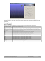
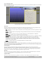
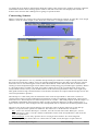
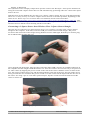
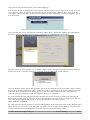
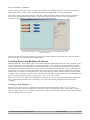
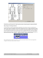
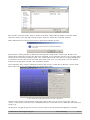
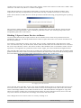
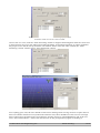
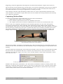
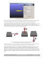
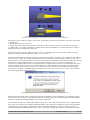
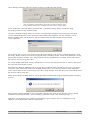
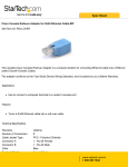
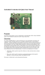
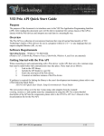
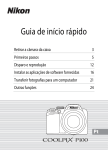
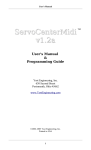
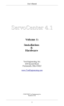
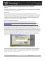
YEI 3-Space Mocap Studio Quick Start Manual
Purpose
The purpose of this manual is to act as a starting point for new users of the YEI 3-Space Mocap Studio,
and to offer tips on how to operate it in a way that ensures it acts as desired. All keyboard commands
will be bold and have braces ([ ]) around them.
Overview
The YEI 3-Space Mocap Studio is a motion capture (mocap) application that was created for
interacting with the YEI 3-Space Sensor™ family. It can load/save motion capture data as either of the
following file formats: BVH (Biovision Hierarchy) or TSH (Three Space Hierarchy). The interaction
between the 3-Space Sensor family and the Mocap Studio may be configured using a tool called the
Node Graph Window. This window uses a series of nodes to dictate how data is manipulated and
changed as it is processed from the sensor to the Mocap Studio. It also can load/save these “nodes”
as .XML files. For further detail, see the full manual document.
Basic Start-up Instructions
Make sure you have successfully run the 3-Space Sensor installer, which can be found at
http://tech.yostengineering.com/3-space-sensor/software-suite/yei-3-space-sensor-softwaresuite#down_and_doc. This will install the drivers needed to use the 3-Space Sensor devices. Once
installed, run the Mocap Studio installer. If you do not have the installer, it can be found at
http://tech.yostengineering.com/3-space-sensor/mocap-studio/yei-mocap-studio#down_and_doc.
Once the application has been installed, start the Mocap Studio by either double-clicking the shortcut
on the Desktop or clicking on the shortcut located in the start menu under All Programs → YEI_3Space_Mocap_Studio. Once started, the computer will scan for any connected 3-Space Sensor devices.
This scan is done as a convenience for the application user so they do not have to tell the Mocap Studio
what 3-Space Sensor devices are plugged in to the computer already. For this guide however, users will
be walked through manually telling the Mocap Studio about the connected devices. In the event that a
serial port is detected on the computer that does not have a 3-Space Sensor device attached, a prompt
will be displayed asking whether the user wishes to “poll” the detected ports to see if the device
attached can be identified. This prompt is known as the Unknown Ports Dialog. An example of this
dialog is pictured below.
The Unknown Ports Dialog and its elements.
For the actions being taken in this guide, it is assumed that all 3-Space Sensor devices being used are
communicating through a 3-Space Sensor Dongle, connected via Bluetooth, or connected through
USB. As such, it is safe to just click the “Ignore ports” button and ignore the text in the dialog. Once
past this dialog, the Mocap Window will be displayed (pictured below). This window is the main
interface with the YEI 3-Space Mocap Studio.
©2007-2012 Yost Engineering Inc.
Patent Pending
1/16
The first window seen when the Mocap Studio is started. This window is known as the Mocap Window.
With this window up, users may now begin to interact with the YEI 3-Space Mocap Studio and create
animations.
Getting Started
Basic Commands
There are a few input commands to be aware of while using the Mocap Studio application.
Left Mouse Button
Selects objects in the 3D view.
Right Mouse Button
Allows the user to rotate the 3D view while pressing and moving the mouse.
Middle Mouse Button Allows the user to translate the 3D view while pressing and moving the mouse.
Scrolling
Allows the user to zoom in/out.
[T]
Enables/Disable the translation GUI when a bone is selected.
[R]
Enables/Disable the rotation GUI when a bone is selected.
[F]
Enables/Disable mouse translation when a bone is selected.
[←]
Snaps the 3D view to view down the positive X-axis.
[→]
Snaps the 3D view to view down the negative X-axis.
[↑]
Snaps the 3D view to view down the negative Y-axis.
[↓]
Snaps the 3D view to view down the negative Z-axis.
[Space]
Allows the user to add/delete/copy bones.
[Shift]
Allows the user to select multiple bones.
©2007-2012 Yost Engineering Inc.
Patent Pending
2/16
User Interface Tour
Before using the YEI 3-Space Mocap Studio, lets take a moment to get familiar with the User Interface
(UI) of the Mocap Window.
The Mocap Window with the UI elements highlighted.
Menu-bar
This bar contains menu categories that range from quitting the application to saving animations and
configuring 3-Space Sensor devices. The Menu-bar is broken down as follows:
File – Users may view the “About” information for the Mocap Studio, run the Setup Wizard, or quit
the application.
Import – Contains options for importing existing animations that have been saved as either BVH
files or TSH files.
Export - Contains options for saving recorded animations as either BVH files or TSH files.
Node Graph – Allows users to open the Node Graph Window.
Settings – Exposes options for users to configure color settings for the 3D View, toggle the visibility
of the YEI logo in the 3D View, toggle whether to prompt about unknown serial ports when
scanning for 3-Space Sensor devices, configure interpolation settings, configure unit settings,
configure bone view settings, toggle pedestrian tracking, and the option to reset all items in the
settings menu to their default.
Scripts – Contains options for re-exporting TSH files as another format.
Current Session Drop-down Box
This drop-down box allows users to change what animation is currently being exposed by the Session
Panel. This means that changes and playback seen in the Session Panel relates to the recording session
selected in the Current Session Drop-down Box.
Session Panel
This area displays information about specific mocap bones, allows users to edit exposed bone
attributes, and allows users to configure animation capture parameters. The Session Panel is divided
into two tabs: the Pose Tab and the Live Tab. The Pose Tab deals with configuring mocap skeletons,
while the Live Tab deals with configuring animation capture sessions.
3D View
This section of the Mocap Window displays a 3D environment that all animations may be viewed in.
Creation and manipulation of mocap skeletons also occurs in the 3D View.
Capture Panel
This area is used when the Mocap Window is on the Live Tab. With no session selected or when
©2007-2012 Yost Engineering Inc.
Patent Pending
3/16
recording the area displays information about the capture, like capture rate, number of frames captured,
and amount of time since starting capture. With a selected session the area displays the number of
frames in the session and a sliding bar for going to specific frames.
Connecting Sensors
Before connecting any sensors, the Node Graph Window must first be opened. To open the Node Graph
Window, click on “Node Graph” in the Menu-bar and select “Configure Node Graph”.
Selecting "Configure Node Graph" from the Node Graph menu in the Menu-bar.
A view of the Node Graph Window. Areas of interest are highlighted.
The Node Graph Window is a very flexible and powerful part of the YEI 3-Space Mocap Studio. With
the tools exposed in this window, users can quickly build pipelines for the data received from 3-Space
Sensor devices to travel through in order to alter the behavior of the data (much like an audio mixer
running a sound sample through various filters before finally being projected through a speaker). Below
is a brief description of what role each part of the window plays in the overall function of the Node
Graph Window. Don't worry if not all the features of the Node Graph Window make sense right away.
This guide will be using a minimal subset of its features and thus not require full knowledge of how the
Node Graph Window operates.
The Workspace is the main point of interaction in the Node Graph Window. This area is meant to
contain objects that represent mathematical operations, means of outputting information, and 3-Space
Sensor devices. These objects are collectively known as "nodes". The main purpose of the Workspace is
to establish relationships between these nodes in order to alter the behavior of data coming from 3Space Sensor devices, and configure how the manipulated data is outputted to the Mocap Studio itself.
The Menu-bar in the Node Graph Window acts much the same as the the Menu-bar in the Mocap
Window, except the menu options are different. The Menu-bar is broken down as follows:
File - Users can clear the Workspace of nodes, save the current state of the Workspace, load a
saved Workspace state, view the "About" information on the Node Graph Window, and close the
Node Graph Window.
Device Settings - Users may open the Sensor Configuration Window for connecting and
configuring 3-Space Sensor devices connected over USB, serial, through a 3-Space Sensor
©2007-2012 Yost Engineering Inc.
Patent Pending
4/16
Dongle, or Bluetooth.
The Information Panel displays output from specific nodes in the Workspace and exposes facilities for
taring all connected 3-Space Sensor devices and automatically generating nodes for connected 3-Space
Sensor devices.
With the basic layout defined, the next step is to connect 3-Space Sensor devices to the Mocap Studio.
There are a variety of ways to connect 3-Space Sensor devices to the Mocap Studio, depending on the
intent of use. These ways are covered in the User's Manual, which can be found here:
http://tech.yostengineering.com/3-space-sensor/mocap-studio/yei-mocap-studio#down_and_doc. This
guide assumes that the 3-Space Sensor devices used are the 3-Space Sensor Dongle and 3-Space Sensor
Wireless devices and have been already paired to each other.
Connecting a 3-Space Sensor Over Wireless Via a 3-Space Sensor Dongle
The first step in connecting a 3-Space Sensor device over wireless is to plug in the 3-Space Sensor
Dongle to the computer. To do this, locate the USB port on the bottom of the dongle. The port is
located on the small side of the dongle facing farthest from the LED light. With the port located, plug
the included USB cord into the port.
Inserting a USB cord into a 3-Space Sensor Dongle.
Once plugged into the dongle, plug the other end of the Mini-USB cord into an available USB port on
the computer and the dongle's LED should turn on. Now the wireless sensor needs only to be powered
on. This is done by flipping the power switch on the side of the sensor. With the sensor in front of the
user, the sensor's buttons facing up, and the LED pointing to the left of the user; the side of the sensor
facing towards the user will have the power switch on it. The switch will be depressed into the case of
the sensor. So using a pen or some other pointed object, flip the switch towards the LED end of the
sensor to turn it on.
Flipping the power switch on a wireless sensor using a pen.
©2007-2012 Yost Engineering Inc.
Patent Pending
5/16
Once powered on, the LED on the sensor should light up.
Now that the dongle is plugged into the computer and the wireless sensor is powered on, the next step
is to connect to them. To do this, first open the Sensor Configuration Window. This can be done by
clicking the “Device Settings” menu from the Menu-bar, then clicking the “Find & Configure” option
from that menu.
The "Find & Configure" option being selected from the "Device Settings" menu.
Once selected, the Sensor Configuration Window will be shown. From this window, the relationships
between a wireless dongle and its wireless sensors may be established and configured.
A view of the Sensor Configuration Window and its elements.
Next the computer must scan for any available 3-Space Sensor Dongles and 3-Space Sensor Wireless
devices. To do this, click the Find Devices Button in the left hand side of the window.
The Find Devices Button being clicked on.
Once clicked, the YEI 3-Space Mocap Studio will scan the computer for all connected 3-Space Sensor
devices. This will be apparent because a small sub-window will appear at the center of the screen with
a load bar. If the Unknown Ports Dialog appears, just click "Ignore Ports" button on the dialog to
continue. Once the small sub-window disappears, the scan is complete.
To verify that the dongles plugged into the computer have been connected, click on the "Dongles &
Paired Sensors" tab in the Device Hierarchy on the left hand side of the Sensor Configuration Window.
Any connected dongle should appear in its list. The format for the listing will be:
DNG–SERIAL_NUMBER.
To verify that the sensors paired to a connected dongle have been connected, click on the dongle's name
tab in the Device Hierarchy on the left hand side of the Sensor Configuration Window. Any connected
or non-connected sensor should appear in its list. The format for the listing will be:
©2007-2012 Yost Engineering Inc.
Patent Pending
6/16
WL_W–SERIAL_NUMBER.
After verifying, close the Sensor Configuration Window by clicking the Done Button in the bottomright corner of the window. This will take the application back to the Node Graph Window.
Once back to the Node Graph Window click the "Generate Sensor Nodes" button in the Information
Panel. This will populate the Workspace with nodes representing the sensors and "output nodes"
necessary for getting data from the sensors to mocap skeleton bones.
The Node Graph Window with several sensor nodes in its workspace. The number
if nodes present in a given user's workspace will vary based on the number of
sensors connected.
Once the nodes have been generated, close the Node Graph Window and return to the Mocap Window.
The sensors are now connected to the application.
Creating Bones and Building Skeletons
With the desired 3-Space Sensor devices connected and the application back at the Mocap Window, the
next step is to create a mocap skeleton. A mocap skeleton, is a collection of connected objects called
“bones”. Much like their namesakes, skeletons are made up of a group of bones that are connected to
one another. Like human bones, the position of one bone influences the position of any connected bone.
For instance, moving one's upper leg will swing the lower leg and foot. The concept of bone positions
influencing one another is an important one, as it is the basis for modern motion capture. In this guide,
a simple 3 bone “skeleton” will be used to demonstrate this. This example skeleton can be thought of as
an arm composed from 3 bones (an upper arm, a lower arm, and a hand).
There are two ways to create a mocap skeleton. The first way is to create the skeleton from within the
YEI 3-Space Mocap Studio. The second way is to import an existing skeleton from a file on the
computer.
Creating a New Skeleton
There are two ways to create a skeleton in the Mocap Studio application. One way, is to use the
Skeleton Setup Wizard found in the Mocap Window's Menu-bar under the “File” menu under “Setup
Wizard”. The wizard is very simple to use and will create a whole human skeleton with 17 bones based
on the height given in a “T” pose.
©2007-2012 Yost Engineering Inc.
Patent Pending
7/16
The Skeleton Setup Wizard window.
Second way, is creating the skeleton bone by bone. This can be a long process if a lot of bones are
wanted, but it also gives the user control of how the bones are laid out when creating the skeleton.
Importing an Existing Skeleton
As mentioned previously the Mocap Studio application can load in previously recorded motion
captures in the form of BVH files and TSH files. BVH files can store a single mocap skeleton along
with a single animation. TSH files can also store a single skeleton with a single animation, but also
save 3-Space Sensor assignments to bones (covered later in the guide). BVH files will commonly be
used for loading and saving motion capture data between multiple applications, while the TSH file
format is mainly useful for saving motion capture data intended to be reviewed in the YEI 3-Space
Mocap Studio at a later time. To load in a skeleton, click the “Import” menu in the Mocap Window's
Menu-bar and click on either “BVH” or “TSH” (depending of the desired file format).
Selecting the “BVH” option from the “Import” menu.
This will bring up a File Hierarchy Browser window. From this window users may navigate the
computer's file system and find files of interest.
©2007-2012 Yost Engineering Inc.
Patent Pending
8/16
The File Hierarchy Browser window.
This window will open in the “demos” folder of the YEI 3-Space Mocap Studio. From this folder,
select the “demo_arm” file and click the “Open” button to import the contained skeleton.
If the TSH format was chosen, users may be presented with this prompt.
This prompt is asking whether to delete the existing nodes made in the Node Graph Window and
replace them with nodes saved to the file being imported. If it is desired to preserve any existing nodes
created in the Node Graph Window, click “No”. If the nodes saved to the file are wanted (perhaps this
is a skeleton saved by the user at an earlier date), then click “Yes”. For this guide, since the desired
nodes have already been created, “No” should be clicked.
Once imported, three “bones” should be visible in the 3D View of the Mocap Window. A bone looks
like a cube with a cone protruding from one of the cube's sides.
A view of the Mocap Window after the arm file is imported.
Once the arm file has been imported, change the value in the Current Session Drop-down Box to
“None” so the bones' positions may be manipulated by the connected sensors. With that, the skeleton is
ready to go.
At this point, it might be good to save the current work in case the unfortunate happens (computer
©2007-2012 Yost Engineering Inc.
Patent Pending
9/16
crashes, power goes out, etc). Just click on the “Export” menu in the Menu-bar and select “TSH”. Once
clicked, a File Hierarchy Browser window will appear.
Name the file and save it somewhere memorable, so the file may later be loaded if needed. Once
exported, the file may be imported at any time and work may continue from where it was left off.
If the chosen format is TSH, the user will be presented with the following prompt during the exporting
process.
This prompt is asking whether to save the nodes created in the Node Graph Window along with the
animation and mocap skeleton. This is usually a good idea. Click “Yes” on this prompt. Now onto
manipulating the bones with sensors.
Binding 3-Space Sensor Devices to Bones
An association between the 3-Space Sensor devices and the bones of the mocap skeleton must be
established. This way, the Mocap Studio knows which 3-Space Sensor devices control which bone of
the mocap skeleton.
Let's start by selecting the “upper_arm” bone. Now go to the “Output Node” drop-down box in the
Pose Tab and select any one of the nodes. Please take note that these are the nodes that were created in
the Node Graph Window earlier. The names of these nodes default to the serial number of the sensor it
represents, so assignment of a particular sensor to the “upper_arm” bone should be straight forward.
The selected node in the drop-down box is bound to the selected bone. This means that orientation data
gathered from the sensor whose serial number matches the name of the selected node in the drop-down
box will influence the orientation of the selected bone (“upper_arm” in this case).
Selecting a node from the “Output Node” drop-down box in the Session Panel with
the “upper_arm” bone selected.
Once selected, next select the “lower_arm” bone and bind another node to it. Perform this process one
more time for the “hand” bone. If the same node is chosen for multiple bones, that node's associated
sensor will simply influence more than one bone at once. The bound bones will appear to copy each
others' movements. If there are not enough unique nodes for each of the three bones, this is also OK.
Any bone without an bound node will simply not animate and remain still.
Next change the Session Panel to the Live Tab by clicking on it.
©2007-2012 Yost Engineering Inc.
Patent Pending
10/16
The Session Panel with the Live Tab's area being displayed. This
should be visible once the Live Tab is clicked.
Once in the Live Tab, click the “Start Streaming” button to begin transmitting data from the connected
3-Space Sensor devices to the YEI 3-Space Mocap Studio. As this data transmits, it will be applied to
the proper bones and the mocap skeleton will animate. Please note that when clicked, the “Start
Streaming” button will turn into a “Stop Streaming” button.
Clicking the “Start Streaming” button in the Live Tab.
A view of the Mocap Window with the example mocap skeleton moving.
If everything goes well, the user should see the bones rotating when moving around a 3-Space Sensor
that was bound to that bone. If asynchronous failed to start, there should have been an error message
that would suggest possible issues and solutions; and the sensor(s) will highlighted in red in the Live
Tab's “Sensor Check-box”. Follow the instructions on this prompt and try again. If nothing is
©2007-2012 Yost Engineering Inc.
Patent Pending
11/16
happening, restart the application and import the saved file and rebind the 3-Space Sensor devices.
The movements on the skeleton may not look quite correct (bones rotating the wrong way for instance).
These types of errors will be accounted for in the next section. As long as all the bones with sensors
associated with them are moving, the application is working correctly.
Once satisfied, click the “Stop Streaming” button in the Live Tab to stop the data transmission and
cease animation. Now that the 3-Space Sensor devices are bound to the mocap skeleton, the final step
is to capture an animation.
Capturing Motion Data
In order to record motion capture data there are a few final considerations:
1. What kind of movement is to be modeled?
2. How will the 3-Space Sensor devices be attached to the actor?
3. The 3-Space Sensor devices must be calibrated for how sensors are mounted to the actor.
Points 1 and 2 are completely dependent on the intended application. For the sake of this guide,
movement of a human arm will be modeled. This application has thus influenced the design of the
mocap skeleton. This decision will also influence our mounting method. Since the intention is to model
the movement of a human arm, the sensors will therefore have to be somehow mounted to the actor's
arm. Many methods are available based on the type of sensor being used, materials available, and
budget. In this example, a part of YEI's Mocap Suit will be used to mount the sensors to the actor.
Please note how the sensors are mounted such that the buttons are facing up and the
LED’s are pointed towards the shoulder. These details will heavily influence the
final configuration steps for the mocap skeleton.
However the method, consistency in mounting is key. This is because the way of which the sensors are
mounted on the actor will influence the final calibration steps of configuring the mocap skeleton/sensor
binding.
Once the method of mounting the sensors has been decided on, the next step is to tell the Mocap Studio
how the sensors are mounted to the actor. To do this, first select the Pose Tab. Once the Pose Tab is
selected, next select the “upper_arm” bone. Once selected, find the “Sensor Pose Orientation” checkbox in the Pose Tab.
A close-up look at the Pose Tab's “Sensor Pose Orientation” check-box and value boxes.
Similar to the “Bone Pose Orientation”, the “Sensor Pose Orientation” defines an initial position. The
difference is that this initial position relates to the sensor as opposed to a bone. Click the “Sensor Pose
Orientation” check-box to enable it. Once enabled, a 3D representation of the bound 3-Space Sensor
(sensor mesh) will be shown over the base of the bone.
©2007-2012 Yost Engineering Inc.
Patent Pending
12/16
The “upper_arm” bone with the “Sensor Pose Orientation” enabled. Note that a
sensor mesh can now be seen on the bone.
If the check-box cannot be checked, make sure that the “Output Node” drop-down box for that sensor
has a value selected that is not “None” and the node selected has a sensor node attached to it.
Once checked, the next step is to manipulate the “Sensor Pose Orientation” value boxes to
communicate to the Mocap Studio how the sensor is mounted. This is done by rotating the sensor mesh
about its three Cartesian axes. This is what the X, Y, and Z value boxes stand for. They represent a
rotation (in degrees) around each of the sensor mesh's axes. Below is a few examples showing how the
X, Y, and Z values effect the overall position of the sensor mesh.
The X, Y, and Z values will rotate the sensor mesh about three defined axes
by the number of degrees inputted into their respective boxes.
Experiment with the X, Y, and Z values to better understand how they effect the position of the sensor
mesh. To return the sensor mesh to its original position, just put 0 in for all three fields.
Now that it is understood how to use the “Sensor Pose Orientation” value boxes, the next step is to set
up the sensor mesh to match the way it is mounted on the actor. To do this, adjust the “Sensor Pose
Orientation” value boxes of the “upper_arm” bone to match the sensor mesh's orientation to the
physical sensor on the actor. In the case of this example, the sensor is mounted such that the LED light
is pointed towards the shoulder of the actor with the buttons facing upward. The sensor mesh must be
rotated on its Y axis to match this, so in the Y value box of the “Sensor Pose Orientation” enter a value
of 90.
©2007-2012 Yost Engineering Inc.
Patent Pending
13/16
A before and after picture of changing the Sensor Pose Orientation.
Note how after changing Y to 90 the sensor mesh is oriented just as described.
Once this is done with the “upper_arm” bone, repeat this procedure for the other two bones. The steps
to do this are:
1. Select the bone in the 3D View.
2. Check the “Sensor Pose Orientation” check-box in the Session Panel if it is not already checked.
3. Change the X, Y, and Z value boxes of the “Sensor Pose Orientation” to match the sensor mesh to
the physical sensor mounted on the actor.
In the case of this example, both the “lower_arm” and “hand” bones' sensor mesh will be set to the
following Sensor Pose Orientation values: X: 0, Y: 90, Z: 0.
Once the orientations have been configured, the final step before recording is to “calibrate” the 3-Space
Sensor devices. Since it is impractical in most cases to perfectly mount a 3-Space Sensor on an actor
(have the sensor sit perfectly flat on an arm for instance) this calibration step will determine how far off
each sensor is and compensate for it. This process is automatic, so very little user interaction is
required. To calibrate the sensors, first ensure that all 3-Space Sensor devices are mounted to the actor.
Once mounted, instruct the actor to position themselves such that their pose matches the pose of the
mocap skeleton in the 3D View. In our case, the actor will have their arm stretched out horizontally.
Once posed, click the “Calibrate Sensors” button in the Pose Tab of the Session Panel. Once clicked,
the following prompt will be displayed.
A dialog prompt with a few instructions to consider when calibrating the sensors.
Follow the instructions of the prompt and click the OK button. Once calibration is completed, switch
the Session Panel to the Live Tab and start the sensor data stream, thus animating the mocap skeleton.
Do this to ensure the mocap skeleton is moving as expected.
Once satisfied, take note of the other options on the Live Tab. One of the options is the “Capture Rate”.
This value box dictates how often the Mocap Studio will record the orientation of the mocap skeleton
in frames per second (fps). Changing this value will make animations look more choppy (lower) or
smoother (higher) depending on how the value is changed. Change this value to some non-zero value.
©2007-2012 Yost Engineering Inc.
Patent Pending
14/16
Once changed, click the “Record” button to begin recording the data stream.
A close-up look at the Live Tab with the “Record” button being clicked.
The recording that will be taking place will record the orientation of the
mocap skeleton 60 times per second based on the current “Capture Rate”.
Once clicked, the “Record” button will turn into a “Stop Recording” button. Click the “Stop
Recording” button to stop capturing data.
Once the “Stop Recording” button is clicked, a prompt will be displayed for naming the recorded
session. The default name is the current time detected by the computer. For this example, a more
human friendly name will be chosen. The recorded session for this example will be named
“arm_animation”.
The prompt for naming the animation recorded session.
Once named, the Current Session Drop-down Box will change to the newly recorded animation. Click
the “Play” button in the Session Panel to playback the recording session. Click “Stop Playback” to stop
playing the animation session. The “Play” button will only playback the recording session selected in
the Current Session Drop-down Box.
To record another animation, simply change the Current Session Drop-down Box to “None” and repeat
the steps discussed in this section.
Exporting to a BVH or TSH file will save only the recorded session selected in Current Session Dropdown Box. This means that if there are multiple animations to save the user must for each animation,
select it from the Current Session Drop-down Box, click “Export” from the Menu-bar, select the desired
file format, and save the file.
If the chosen format is TSH, the user will be presented with the following prompt during the exporting
process.
This prompt is asking whether to save the nodes created in the Node Graph Window along with the
animation and mocap skeleton. This is usually a good idea. Click “Yes” on this prompt.
With that, one should now be capable of connecting 3-Space Sensor devices, building a mocap
skeleton, record animations, and save animations.
©2007-2012 Yost Engineering Inc.
Patent Pending
15/16
YEI Technology
630 Second Street
Portsmouth, Ohio 45662
Toll-Free: 888-395-9029
Phone: 740-355-9029
www.YeiTechnology.com
www.3SpaceSensor.com
Patents Pending
©2007-2012 Yost Engineering Inc.
Printed in USA