1
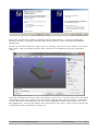
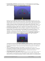
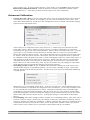
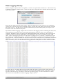
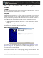
3-Space Sensor Quick Start Manual (Data-Logging
Version)
Purpose
The purpose of this manual is to act as a starting point for new users of the 3-Space Sensor, and to offer
tips on how to operate it in a way that ensures it acts as desired.
Overview
The 3-Space Sensor is an Attitude and Heading Reference System which uses a 3-axis accelerometer,
gyroscope, and compass to determine which way it is facing(its orientation) relative to some reference
orientation. A reference orientation can be manually set, but if not it will use the direction of gravity as
down, the direction of north as forward, and the cross product of gravity by north as right. The sensor
can send orientation data to a PC using a USB or RS232 connection. It can also use this connection to
send any of the other data it provides, like acceleration data, and to allow its parameters to be modified.
For a complete listing of these parameters/data and the commands that are used to access them, see the
Protocol Reference in the User's Guide document. The sensor can communicate in two modes:
•
•
ASCII mode, which is good for using with a terminal, as it takes and returns data in a human
readable form
Binary mode, which is good for using from a programming language and when speed is
important, as it takes and returns smaller, fixed length pieces of data
Once again, for further detail, see the aforementioned documents.
Basic Startup Instructions
Run the latest 3-Space Sensor installer, which can be found at https://www.yeitechnology.com/yei-3space-sensor-software-suite. This will install the drivers needed to use the 3-Space Sensor, as the 3Space Suite, a program which displays the current orientation of the sensor graphically and offers a UI
to many of the options the sensor offers. It also offers a terminal mode in which you may interface
with the sensor using text-based commands.
Once these have been installed, plug the 3-Space Sensor into one of your computer's USB ports. Make
sure that the LED on the sensor turns blue. If not, try plugging it in again.
If the computer recognizes it, the “Found New Hardware Wizard” will appear.
©2007-2013 Yost Engineering, Inc.
Patent Pending
1/7
Select “No, not this time” and then “Install the software automatically”. Two more “Found New
Hardware Wizards” will appear, select the same options on these. After a moment the installation
should finish.
We may now check to ensure the 3-Space Sensor is working. The easiest way to do this is to run the 3Space Suite. Upon running this program, there will be a list of COM ports in the lower left hand
corner.
Select the COM port from the list which corresponds to your sensor. If you are unsure as to which port
corresponds to your sensor, look to see if one of them is labeled with your type of sensor. Alternately,
you can check the list of COM ports with your sensor unplugged, and then recheck the list once you
have plugged it in. If a new port appears, this corresponds to your sensor. Once you have chosen your
COM port, the suite will attempt to connect to it.
©2007-2013 Yost Engineering, Inc.
Patent Pending
2/7
Sensor Calibration
Run the 3-Space Suite, and select your COM port from the list. You should see a model of the sensor
that rotates along with the actual sensor.
The sensors are calibrated at the factory, but due to changes in environment, the sensor may need to be
recalibrated at the application site. Move the sensor around and see if its orientation in the real world
matches the one rendered on screen. If it does not match, calibration may be needed.
Basic Calibration
•
•
Calibrate gyroscope: The gyroscope needs to be calibrated while the sensor is stationary so it
can get an idea of what readings correspond to no motion. Hold the sensor still and press the
Calibrate Gyros button. Continue to hold the sensor still for a second after that, and gyroscope
calibration will be complete.
Tare sensor: Following this, the sensor most likely needs to be tared. Taring sets a certain
sensor orientation as the “zero” point. This is always represented on screen by the sensor with
its top(button side) up and the cord facing directly towards you. Therefore, to put the sensor in
an appropriate taring position, you should make sure the physical sensor has its top up and its
cord facing directly towards you. You will probably also want to place it on a flat surface to
help line it up. Once you have it in the proper position, press the Tare button in the suite. The
command will finish immediately, so you may begin moving the sensor around after that. The
movement of the on-screen sensor should now much more closely match that of the real sensor.
Commit Your Settings
Once you have the sensor properly calibrated, you will want to save your changes so you don't have to
make them again every time you plug in your sensor. To commit your settings to the sensor's nonvolatile memory, press the Commit Settings button. Be sure to do this each time you make changes
you want to keep. If you decide later that you want to return to the original settings and try again, use
the Restore Factory Settings menu option. This will return all settings to their original states, though
this change will also not be saved unless you commit it.
Dealing with Small Errors
You may find that while the on-screen orientation may be close to the actual sensor's orientation, in
some places it will still have a small error(this is easiest to see when holding it so any edge is flat
against a surface and another edge is facing the screen). There are several methods for correcting this:
©2007-2013 Yost Engineering, Inc.
Patent Pending
3/7
•
•
•
•
Perform sphere calibration: The Suite provides a wizard that allows users to perform a
calibration similar to the one performed at the factory. Go the Sensor menu and select Run
Sphere Calibration Wizard. The following window will appear:
Rotating the sensor will cause the sphere to rotate as well. The cyan and yellow arrows will
paint their colors on the sphere wherever they touch. Any area they both paint will turn green.
The goal of this wizard is to more or less turn the entire sphere green. The reason for this is that
if both of these arrows have touched the entire sphere, this is a good sign that the data set that
has been collected from the sensor provides a decent representation of all possible values.
Another good metric is that the estimated density has dropped to around 30 to 60. Once you are
satisfied that the sphere is decently filled in, hit Finish and new calibration parameters will be
calculated for your sensor. Make sure to commit the new settings if they seem to help.
Perform ortho-calibration: The sphere calibration is excellent for fixing overall sensor error,
but sometimes magnetic effects can twist orientation readings in a way that requires a more
specific solution. In cases where after sphere calibration some orientations still are off, orthocalibration is the recommended solution. Ortho-calibration is layered on top of sphere
calibration, so both can be used in unison. This also means that if you reperform sphere
calibration, you should also reperform ortho-calibration if you would like to continue using it.
To perform ortho-calibration, go to the Sensor menu and select Run Ortho Calibration
Wizard. When prompted to choose a calibration method, choose “Ortho Calibration”.
A small picture of the sensor will appear, indicating a certain orientation you should be placing
your sensor in. Place the sensor in that orientation and hit the Next button. When you press the
Next button, the picture will move on to the next orientation, and so on until it has guided you
through all the orientations. After this has been done, check the orientation to see if the error
still exists.
Turn on continual auto-reference vector mode: In its default state, the sensor will
automatically calculate the compass reference vector when it starts up. However, it can be set
to continually recalculate this, allowing it to adjust the reference vector on the fly. To set up
this mode, click the Single Auto Continual radio button. Note that in this mode, the
accelerometer reference vector is always (0,1,0).
Set up multi-reference vector mode: Though usually not necessary, multi-reference mode can
provide a third layer of calibration on top of the parameters given by sphere calibration and
ortho-calibration. This mode keeps a list of 24 reference vectors, one for every unique position
the sensor can arrive at using only 90 degree rotations, starting with the zero orientation(top up,
©2007-2013 Yost Engineering, Inc.
Patent Pending
4/7
plug towards you). To set up multi-reference vector mode, go to the Sensor menu and select
Run Ortho Calibration Wizard. When prompted to choose a calibration method, choose
“Multi Reference”. After this, perform the same steps as for ortho-calibration.
Advanced Calibration
•
•
•
Change the trust values: If you are using the sensor in an environment that involves spurious
acceleration(a moving vehicle, for example), you may want to modify the trust values. The
trust values determine how much one of the component sensors is trusted. Choose the Settings
option from the Advanced menu.
Trust values for a component sensor range from 0 to 1, with 0 being not trusted at all, and 1
being fully trusted. This is relative to the gyroscope, so if the accelerometer or compass is
trusted less, the gyroscope will pick up the slack. These values are usually kept low(<.2) as the
gyroscope is very accurate over the short term, and the other two sensors are just needed to
ensure that it doesn't drift over time. You will see that there are two modes for each trust value.
In “Static” mode, the sensor will use a fixed trust value for the component sensor in question.
In confidence mode, the final trust value is closer to the higher of the two values if the sensor is
still, and closer to the lower if the sensor is moving. When using the sensor in environments
with different amounts of acceleration or different types of sensor motion, experiment with
these values to see what results they yield. Be sure to hit Save for your changes to take effect.
(Note that this will not commit the changes to long term memory).
Smoothing out the results: If you would like the orientation coming out of the sensor to be
smooth at the expense of responding quickly, you can set up a running average. Choose the
Settings option from the Advanced menu. On this screen you will see a field labeled Running
Average Percent.
When this is 0, no smoothing will be done. It can be as much as 97, which indicates that 97%
of each orientation is composed of averaged previous orientations. At 97% the orientation will
be very smooth, but will respond more slowly. Experiment with this value to find the right
combination of response and smoothness. Be sure to hit Save for your changes to take effect.
(Note that hitting Save will not commit the changes to non-volatile memory, it will only cause
them to take effect for the current session. To keep the changes, commit them as described
above.)
Oversampling: The same settings window contains an oversampling setting. This value can be
between 1 and 10, where 1 means only one sample is taken per orientation calculation, and 10
means 10 samples are taken per calculation. A higher value for this will cause orientations to be
calculated more slowly, but will also reduce noise. Experiment with this value if you need to
reduce sensor noise, and be sure to commit the setting afterwards if it is suitable.
©2007-2013 Yost Engineering, Inc.
Patent Pending
5/7
Data-Logging Startup
Before using the 3-Space Sensor to log data, it is best to set up the date and time on it. The easiest way
to do this is using the 3-Space Suite. Connect to the sensor using the suite, open the Sensor menu, and
select Sensor Info.
Press the “Set Time to System Time” button. This will set the time on the sensor to your computer's
current time. The SD card comes formatted, but the “Format SD Card” button will reformat it should
the need ever arise. The SD card can also be reformatted by any formatting utility, so long as it can
format the card with a FAT32 filesystem.
By default, the Data-Logging 3-Space Sensor can start a data-logging session containing the date, time,
and orientation in quaternion form by pressing the left button when the sensor is not attached to a
computer. While the session is ongoing, the LED should flash yellow and green. This session can be
stopped by either pressing the right button or by plugging the sensor into a computer using a USB
cable. After a data-logging session, once the sensor is plugged in to a computer, it should show up on
the computer as another storage drive. A directory will have been created corresponding to the datalogging session. It will be named after the time of the session, and the directory's timestamp will match
this time as well. Inside this directory should be a single file named data.txt. Opening this up in an
editor will allow you to view the data that was logged, which at this point will be in a human-readable
form.
To change the way in which data is logged, look inside the capture.cfg file in the Config directory on
the SD card's drive. The properties in this file can change data-logging settings such as how often to
log data, what data to log, and when to start and stop data-logging. For more information on these,
refer to the User's Manual for the Data-Logging 3-Space Sensor.
©2007-2013 Yost Engineering, Inc.
Patent Pending
6/7
YEI Technology
630 Second Street
Portsmouth, Ohio 45662
Toll-Free: 888-395-9029
Phone: 740-355-9029
www.YeiTechnology.com
www.3SpaceSensor.com
Patents Pending
©2007-2013 Yost Engineering, Inc.
Printed in USA