1
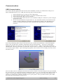
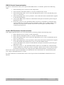
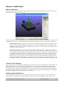
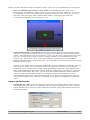
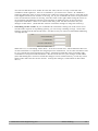
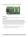
Embedded Evaluation Kit Quick Start Manual
Purpose
The purpose of this manual is to act as a starting point for communicating with the 3-Space Embedded
Sensor via the Embedded Evaluation Kit and the 3-Space Sensor Suite.
Overview
The 3-Space Embedded Sensor is a sensor unit which uses 3-axis accelerometers, gyroscopes, and
compasses in order to determine which way it is facing(its orientation) relative to some reference
orientation. A reference orientation can be manually set, but if not it will use the direction of gravity as
down, the direction of north as forward, and the cross product of gravity by north as right. The sensor
can send this data to a PC using a USB or RS232 connection. It can also be interfaced directly with a
microcontroller by utilizing either its SPI or UART interfaces. This is also the means by which any of
the options the sensor offers can be used, and any other piece of data the sensor offers may be read.
For a complete listing of these options/data and the commands that are used to access them, see the
Protocol Reference in the User's Guide document. The sensor can communicate in two modes:
•
ASCII mode, which is good for using with a terminal, as it takes and returns data in a human
readable form
•
Binary mode, which is good for using from a programming language and when speed is
important, as it takes and returns smaller, fixed length bits of data
Once again, for further detail, see the aforementioned documents.
1/8
Basic Startup Instructions
Run the supplied 3-Space Sensor installer, which can be found at http://tech.yostengineering.com/3space-sensor/software-suite/yei-3-space-sensor-software-suite#down_and_doc. Download the latest
Suite installer in the Download section. This will install the drivers needed to use the 3-Space Sensor,
as well as a few demo applications with which to test it:
•
The 3 Space Suite, a program which displays the current orientation of the chip graphically and
offers a UI to most of the options the sensor offers, and which also offers a terminal mode in
which you may interface with the sensor using text-based commands.
•
The Bird Sample, a demo which lets you fly around as a bird using the sensor.
©2007-2011 Yost Engineering, Inc.
Patent Pending
2/8
Communication
USB Communication
First ensure that the appropriate drivers have been installed. In order to communicate with your 3Space Embedded Sensor over USB, the following steps should be taken:
1.
2.
3.
4.
Ensure that the power switch is in the off position.
Ensure that the TSS-EM module is correctly installed in the socket.
Ensure that jumper JP2 is set to position 1.
Connect the mini USB connector to an available USB port on the host system using an
appropriate cable.
5. Power the Embedded Development Kit on. The TSS-EM module will enumerate and
create a virtual COM port to facilitate communication. Refer to the TSS-EM User's
Manual for detailed information describing the TSS-EM module communication
protocol.
If you are performing these steps for the first time, the “Found New Hardware” wizard will appear:
Select “No, not this time” and then “Install the software automatically”. Two more “Found New
Hardware Wizards” may appear, select the same options on these. After a moment the installation
should finish. We may now check to ensure the 3-space sensor is working. The easiest way to do this
is to run the 3 Space Suite. Upon running this program, there will be a list of COM ports in the lower
left hand corner.
You can either select a COM port from this list if you are aware of which COM port was just installed
for your sensor(i.e. it wasn't there before installing the sensor), or you can hit the Auto-Detect button in
order to verify which COM ports belong to 3-space sensors. Please be aware that Auto-Detect will
attempt to communicate with all COM devices on your system. Once you have chosen your COM
port, the suite will attempt to connect to it.
©2007-2011 Yost Engineering, Inc.
Patent Pending
3/8
RS232 Serial Communication
In order to communicate with your 3-Space Embedded Sensor over RS232, perform the following
steps:
1. Ensure that the power switch is in the off position.
2. Ensure that the TSS-EM module is correctly installed in the socket.
3. Ensure that jumper JP2 is set to select the appropriate power source and that the power
source is connected.
4. Ensure that jumper JP1 is set to position 1. This routes the serial communication signals
to the TSS-EM module.
5. Connect the DB9 serial connector to the RS232 serial port on the host system using an
appropriate cable.
6. Power the system on. The TSS-EM module will now be available for communication
via the COM port to which the system is attached. (Often, this is COM1). Refer to the
TSS-EM User's Manual for detailed information describing the TSS-EM module
communication protocol.
Serial SPI Emulation Communication
When RS232 SPI Emulation use of the TSS-EEVK is desired, perform the following steps:
1. Ensure that the power switch is in the off position.
2. Ensure that the TSS-EM module is correctly installed in the socket.
3. Ensure that jumper JP2 is set to select the appropriate power source and that that power
source is connected.
4. Ensure that jumper JP1 is set to position 2. This routes the serial communication signals
to the TSS-EEVK SPI emulation processor on the TSS-EEVK board.
5. Connect the DB9 serial connector to the RS232 serial port on the host system using an
appropriate cable.
6. Power the system on. The TSS-EM module will now be available for communication
via the COM port to which the system is attached. Refer to the section 4 of this manual
for detailed information describing the TSS-EEVK SPI emulation command protocol.
Please refer to the 3-Space Embedded User's Manual for more information on communicating with
your 3-Space Embedded Sensor via SPI.
For other methods of communication refer to the 3-Space Sensor Embedded Evaluation Kit User's
Manual.
©2007-2011 Yost Engineering, Inc.
Patent Pending
4/8
Sensor Calibration
Basic Calibration
Run the 3 Space Suite, and select your COM port from the list. You should see a model of the sensor
that rotates along with the actual sensor.
At this point, the on-screen orientation may not line up very well with the actual sensor, as we have not
calibrated the sensor yet. The following steps should ensure that your sensor is properly calibrated.
•
Calibrate gyroscope: The gyroscope needs to be calibrated while the sensor is stationary so it
can get an idea of what readings correspond to no motion. Hold the sensor still and press the
Calibrate Gyros button. Continue to hold the sensor still for a second after that, and gyroscope
calibration will be complete.
•
Tare sensor: Following this, the sensor most likely needs to be tared. Taring sets a certain
sensor orientation as the “zero” point. This is always represented on screen by the sensor with
its top(button side) up and the cord facing directly towards you. Therefore, to put the sensor in
an appropriate taring position, you should make sure the physical sensor has its top up and its
cord facing directly towards you. You will probably also want to place it on a flat surface to
help line it up. Once you have it in the proper position, press the Tare button in the suite. The
command will finish immediately, so you may begin moving the sensor around after that. The
movement of the on-screen sensor should now much more closely match that of the real sensor.
Commit Your Settings
Once you have the sensor properly calibrated, you will want to save your changes so you don't have to
make them again every time you plug in your sensor. To commit your settings to the sensor's nonvolatile memory, press the Commit Settings button. Be sure to do this each time you make changes
you want to keep. If you decide later that you want to return to the original settings and try again, use
the Restore Factory Settings menu option. This will return all settings to their original states, though
this change will also not be saved unless you commit it.
Dealing with Small Errors
You may find that while the on-screen orientation may be close to the actual sensor's orientation, in
some places it will still have a small error(this is easiest to see when holding it so any edge is flat
©2007-2011 Yost Engineering, Inc.
Patent Pending
5/8
against a surface and another edge is facing the screen). There are several methods for correcting this:
•
Turn on continual auto-reference vector mode: In its default state, the sensor will
automatically calculate the compass reference vector when it starts up. However, it can be set
to continually recalculate this, allowing it to adjust the reference vector on the fly. To set up
this mode, click the Single Auto Continual radio button. Note that in this mode, the
accelerometer reference vector is always (0,-1,0).
•
Set up multi-reference vector mode: If the previous option didn't solve the problem, multireference vector mode may be the answer. It requires more setup, but can provide much better
results. This mode keeps a list of 24 reference vectors, one for every unique position the sensor
can arrive at using only 90 degree rotations, starting with the zero orientation(top up, plug
towards you). The easiest way to set up multi-reference vector mode is to use the MultiReference Wizard, which is part of the Suite. Go to the Other Commands menu and select Run
Multi Reference Wizard.
A green version of the sensor will appear, indicating a certain orientation you should be placing
your sensor in. When you press the Next button, the green board will move on to the next
orientation, and so on until it has guided you through all the orientations. After this has been
done, click the Multiple radio button, and see if the error still exists. If a certain one of the 24
orientations still seems to have error, you can press the Set Multi Reference button while the
sensor is in this orientation(the actual sensor, not the on-screen representation; be sure to
understand this distinction). This should lessen the error. Keep in mind that multi-reference
vector mode changes do not need to be committed; all changes are automatically saved to the
sensor.
Advanced Calibration
•
Change the rho values: If you are using the sensor in an environment that involves spurious
acceleration(a moving vehicle, for example), you may want to modify the rho values. The rho
values determine how much one of the component is trusted. Choose the Settings option from
the Advanced menu.
©2007-2011 Yost Engineering, Inc.
Patent Pending
6/8
You will see that there are 2 modes for each rho value, but we are only concerned with
confidence mode right now. Next to “Confidence” you will see two values. In confidence
mode, the final rho value is closer to the lower of the two values if the sensor is still, and closer
to the higher based on how much it is moving. So, if you would like the sensor to respond less
to the accelerometer while it is moving, raise the value on the right. When using the sensor in
environments with different amounts of acceleration or different types of sensor motion,
experiment with these values to see what results they yield. Be sure to hit Save for your
changes to take effect. (Note that this will not commit the changes to long term memory).
•
Smoothing out the results: If you would like the orientation coming out of the sensor to be
smooth at the expense of responding quickly, you can set up a running average. Choose the
Settings option from the Advanced menu. On this screen you will see a field labeled Running
Average Percent.
When this is 0, no smoothing will be done. It can be as much as 97, which indicates that 97%
of each orientation is composed of averaged previous orientations. At 97% the orientation will
be very smooth, but will respond more slowly. Experiment with this value to find the right
combination of response and smoothness. Be sure to hit Save for your changes to take effect.
(Note that hitting Save will not commit the changes to non-volatile memory, it will only cause
them to take effect for the current session. To keep the changes, commit them as described
above.)
©2007-2011 Yost Engineering, Inc.
Patent Pending
7/8
YEI Technology
630 Second Street
Portsmouth, Ohio 45662
Toll-Free: 888-395-9029
Phone: 740-355-9029
www.YeiTechnology.com
www.3SpaceSensor.com
Patents Pending
©2007-2011 Yost Engineering, Inc.
Printed in USA
©2007-2011 Yost Engineering, Inc.
Patent Pending
8/8