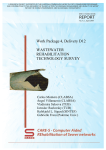
1
USER MANUAL
Revision 2.0
01.2004
www.radiodetection.com
90/UG062EURO
itrack User Manual
Introduction
Foreword
i
It is important that you read this user manual before operating your Radiodetection track system, however this
manual and all its contents are subject to change. Radiodetection products are under continuous development and are
subject to change. Radiodetection Limited reserves the right to modify the product without notice and some product
changes may have taken place after this user manual was published. Contact your local Radiodetection dealer for
the latest information on Radiodetection track.
i
Copyright © by RADIODETECTION TRENCHLESS PRODUCTS, a division of RADIODETECTION LTD. All rights reserved.
i
The track system is covered by the following Patents: US 5,917,325; US 6,107,801; US 6,606,032; GB2,330,204;
EP 0,815,472; and other Patents pending
Important Notice
Radiodetection makes every effort to ensure that all technical information, statements and recommendations
about Radiodetection Trenchless products are based on information believed to be reliable, but the accuracy or
completeness thereof is not guaranteed. In no event shall Radiodetection be liable for any loss, inconvenience,
damage or problems caused through use of the equipment.
Before using the product, the user should determine the suitability of the product for its intended use. The user
assumes all risks and liability whatsoever in connection with such use.
Compliance Statement
When used in accordance with the user manual, relevant parts of this product comply with ‘The Essential
Requirements of the Radio Equipment and Telecommunications Terminal Equipment Directive’ (1999/5/EC) and/or
EMC Directive (89/336/EEC) for use in a residential, commercial and light industry environment, as required.
As appropriate, this equipment complies with the following:FCC Part 90, FCC Part 15, EN 300 220-3, EN 300 330, EN 301 489-3
Appropriate radio transmissions from the equipment have been certified by the FCC. The following FCC IDs apply:
K68ND2585A, E86DTR100
This product must only be used with the antennas supplied with it. This product must not be connected to the mains
supply, either directly or indirectly via an adapter or battery eliminator. Such connection, use with other antenna or
any changes, or modifications made to this product not expressly approved by Radiodetection Ltd could void the
user’s authority to operate the equipment.
Note: Appropriate parts of this equipment have been tested and found to comply with the limits for a Class B digital
device, pursuant to part 15 of the FCC Rules. These limits are designed to provide reasonable protection in a
residential installation. This equipment generates, uses, and can radiate radio frequency energy and, if not installed
and used in accordance with the user manual, may cause harmful interference to radio communications. However,
there is no guarantee that interference will not occur in a particular installation. If this equipment does cause
interference to radio or television reception, which can be determined by turning the equipment off and on, the user is
encouraged to correct the interference by one or more of the following measures:
•
•
•
Reorient or relocate the receiving antenna.
Increase the separation between the equipment and receiver.
Consult your Radiodetection office for help.
•
•
•
All track units are NEMA 3R / IP54 weatherproof.
All track units meet shock and vibration standard IEC68
All track units are manufactured according to the International Quality Norm ISO 9001
i
i
i
Page 2
itrack User Manual
Table of Contents
Table of Contents
Warnings and Precautions.......................................................................................5
itrack Systems Overview..........................................................................................8
1.0
2.0
3.0
4.0
5.0
itrack Receiver................................................................................................10
1.1
1.2
1.3
User Interface
Useful key combinations:
Setup
1.3.1 To enter Set-up:
1.3.2 Key functions during Set-up
10
11
12
12
12
1.4
Calibration
1.4.1 Preparation for calibration:
1.4.3 To calibrate the receiver:
13
13
13
Receiver Operation.........................................................................................14
2.1
Tracking Mode
2.1.2 To track a bore
14
15
2.2
Steering mode
2.2.1 To check the Drill-head direction
16
16
2.3
Depth Measurement
2.3.1 Automatic Depth Measurement:
2.3.2 Manual Depth Measurement
19
19
19
Dataview..........................................................................................................20
3.1
3.2
Function Keys
DataView Operation
3.2.1 Remote Steering
20
21
21
The DataSonde...............................................................................................24
4.1
Correct installation into the drill-head
24
DataSonde Operation....................................................................................25
5.1
5.2
5.3
Standby mode
Park mode
Dual frequency DataSondes
5.3.1 To change DataSonde frequency
25
25
25
25
5.4
5.5
Temperature Alarms
Runtime Indicator
26
26
Page 3
itrack User Manual
6.0
7.0
8.0
9.0
Table of Contents
Wireline Control Unit.....................................................................................27
6.1
6.2
Fascia
Connections
27
27
Wireline Operation.........................................................................................28
7.1
7.2
Wireline Connection
Wireline Usage
28
29
Support Stand................................................................................................30
8.1
To setup the support stand
30
Rechargeable Battery System......................................................................31
9.1
Charging
31
10.0 BoreLogger.....................................................................................................32
10.1
10.2
10.3
10.4
To record drilling data to the receiver
To add a simulated locate point:
To delete the last log
To finish logging
32
32
32
32
11.0 BoreLog Software..........................................................................................33
11.1
Installation:
33
12.0 Borelog Operation.........................................................................................36
12.1
12.2
To upload drilling data to the BoreLog PC software
To export data from the BoreLog software to MS Excel
36
37
13.0 Tips and Tricks...............................................................................................38
13.1
13.2
Troubleshooting Guide.
Angle conversion table
38
40
14.0 Technical Specifications...............................................................................41
14.1
14.2
14.3
14.4
14.5
14.6
14.7
Receiver
DataView
Borelogger
DataSonde
Rechargeable Battery System
Wireline Control Unit
Support Stand
41
42
42
42
43
43
43
Warranty...................................................................................................................44
Registration Card....................................................................................................45
Page 4
itrack User Manual
Warnings and Precautions
Warnings and Precautions
It is very important that Directional drilling operators note the operating procedures and safety precautions before
operating the Radiodetection track system.
i
Priority must be given to local and national safety requirements at all times.
All other safety procedures should be followed.
All underground utilities MUST be located before starting the drilling operation.
Contact your local Radiodetection dealer for pipe and cable locating equipment.
Serious injury and death can result if underground drilling equipment accidentally
hits an underground utility.
Operators must wear protective safety clothing such as insulated boots, insulated
gloves, high visibility safety vests, safety glasses and hard hats.
When using Lithium batteries, care must be taken to avoid drilling conditions which would
result in the DataSonde exceeding the battery manufacturers recommended maximum
operating temperature. In the event of exceeding this temperature the battery may vent toxic
fumes into the sealed battery compartment and may explode if the temperature rises further.
•
Ensure that the battery manufacturers specified maximum operating temperature
exceeds 100°C.
•
Follow all safety and handling precautions specified and supplied by the battery
manufacturer.
•
If the warranty temperature indicator of the DataSonde, located next to the slot of the
anti-roll pin, has turned black then the DataSonde temperature has exceeded 104° C.
Do not remove the battery end cap as toxic fumes or harmful chemicals may be released.
i
The track system is not explosion-proof and is not approved for use in areas
where hazardous gases may be present.
i
The track system should never be used near flammable or explosive substances.
i
Prior to the start of each drilling operation, the following actions must be taken:
• An orientation working practice should be selected which is done in the
Receiver Setup Menu. (see page 12)
• Confirm that the itrack system is operating properly and check for an accurate
location of the drillhead and accurate depth readings, Tilt angle and Roll position
with the DataSonde inside the drillhead.
Page 5
itrack User Manual
i
Warnings and Precautions
During drilling, the depth readings and locate position will not be accurate unless:
• A consistent orientation working practice will be maintained. (changing from facing the
Drilling machine to working with one’s back to the Drilling machine or visa versa could result
in both a mis-locate and/or a depth error). This effect is more likely to happen after
approximately 10% Grade (5°) of Tilt angle.
Note: at any time the user may go back into the “Setup Menu” and change the orientation
method. This will not effect the Receiver’s calibration.
•
The Receiver has been calibrated correctly.
Interference can cause inaccuracies in depth readings, loss of Tilt angle and/or Roll position and
inaccurate location and heading of the drillhead.
•
Sources of interference could be power lines, cable TV, traffic signal loops, telecom
lines, pipelines, metal structures, invisible dog fences, radio frequencies,
transmission towers and cathodic protection systems.
•
Due to the nature of the equipment it may be susceptible to electromagnetic fields
emitted by other apparatus. This may cause incorrect data to be displayed.
NimH batteries should be disposed of in accordance with your Company’s work practice,
and/or the relevant law or guidelines in your country.
Carefully review this user manual. If you have any questions regarding the operation of the
equipment or if you have difficulty on the job, please contact your local Radiodetection dealer
for help.
Page 6
itrack User Manual
Serial Numbers
Dear Customer:
i
We would like to congratulate you with the purchase of your Radiodetection track horizontal boring guidance system.
Please take the time to read this user manual and fill out this page for your own records. When contacting your
Radiodetection dealer, it is important to quote the equipment serial numbers.
Also, please fill out the warranty registration card, that you will find on the last page of this user manual and
send it to your Radiodetection dealer. Registration entitles you to free software updates.
i
The track system comprises:
itrack Receiver
Serial No. ................................................
Part No. 10/ND2703-USA or 10/ND2703-EUR
itrack DataView
Serial No. .................................................
Part No. 10/ND2704-USA or 10/ND2704-EUR
Wireline Control Unit
Serial No. .................................................
Part No. 10/ND2599
Short Range DataSonde (SDS)
Serial No. .................................................
Part No. 10/ND1579
Precision Dual Frequency DataSonde (PDF)
Serial No. .................................................
Part No. 10/ND2585
Rechargeable Battery System
Serial No. .................................................
Part No. 10/ND2743-DC
Spare Battery Stick (3 required)
Serial No. .................................................
Part No. 65/ND2161
Borelog SOftware CD
Serial No. .................................................
Part No. 97/ND2733
i
Thank you for choosing the Radiodetection track system.
Radiodetection Trenchless Products
Page 7
itrack User Manual
itrack System Overview
itrack Systems Overview
itrack: A Tracking and Guidance System for Horizontal, Directional Drilling Machines
The itrack system provides accurate walkover guidance information for horizontal directional drilling machines.
Keeping a bore on track, on time and within budget are essential criteria for the trenchless industry. To meet these
criteria and with speed, accuracy and usability as the main priorities, Radiodetection have developed the itrack System.
The system comprises an itrack receiver, a DataView unit, one or more DataSonde and Radiodetection’s Borelog
software.
Receiver
i
The track receiver uses automatic tracking arrows and enhanced interference rejection technology to guide the
operator to the drillhead quickly and accurately.
•
•
•
•
•
•
•
Down-hole frequency change to overcome localised interference
Integral BoreLogger
Integral support stand
Alarm warnings for high DataSonde temperature and low battery level
Automatic tracking arrows for accurate underground position and depth
Drill head direction compass indicator and tilt angle in % of grade or degrees
Real-time radio link to DataView
DataView
i
The track DataView uses a row of nine LED’s to provide remote steering information. The large LCD also displays real
time data transmitted from the DataSonde via the track Receiver, including Tilt angle (Inclination), Roll position (clock),
Depth, Remote Left/Right steering and Alarm Conditions.This enables drilling machine operators to accurately steer a
drill head left and right, maintaining a safe and precise drilling operation.
•
•
•
•
•
•
•
i
Remote steering
Down-hole frequency change to overcome localised interference
Alarm warnings for high DataSonde temperature and low battery level
Real-time transmission of roll position and tilt angle from DataSonde to receiver to DataView
Continuous on screen DataSonde temperature
Interface to Wireline Control Unit
12V DC external input
DataSonde
The DataSonde, housed in the drillhead emits a locate signal and transmits information about its position and status,
including Tilt angle (Inclination), Roll position (clock) and temperature information.
•
•
Dual Frequency operation, preventing the need to pull back and change equipment.
Compatible with wireline operation, when using a battery adapter.
Page 8
itrack User Manual
itrack System Overview
Wireline Control Unit
The Wireline Control Unit provides an alternative method of powering the PDF DataSonde, giving increased accuracy
under a wider range of interference conditions. A power and communication line runs from the Wireline Control Unit,
inside the drilling rods to the DataSonde. The Wireline Control Unit can also be connected to the DataView giving a
direct display of DataSonde operating conditions.
•
•
•
•
Data recovery without relying on the ability to walkover with a receiver
Operating time not limited by DataSonde battery life
Powered by 12 -24V DC supply
Detection of wire open and short circuit fault conditions
Borelog
Radiodetection’s BoreLog is an advanced software package for a Microsoft® Windows® based PC, which allows the
user to download drilling data stored in the track Receiver.
i
•
•
•
Electronic storage of a complete drilling profile
Automatic report generation
Export data Microsoft™ Excel
Page 9
itrack User Manual
Receiver
1.0
itrack Receiver
1.1
User Interface
K
11
10
5
9
1.
2.
3.
4.
5.
6.
7.
8.
9.
10.
11.
8
7
6
Depth Display: Shows the DataSonde depth and reports its runtime when the Information Key
is pressed.
Locate Arrows: Used to direct the operator when in Locate Mode.
Sonde Info Display: This section of the screen displays the current sonde frequency and
battery status.
Clock: Reports the DataSonde’s roll position.
Receiver Info Display: This section of the sceen displays the receiver’s battery status.
Information Key: This displays the information screen giving details of:
•
The selected DataSonde operating frequency
•
The DataSonde battery status
•
The DataSonde operating temperature
•
The DataSonde runtime (if supported by the datasonde in use)
•
The receiver battery status
•
The selected location orientation i.e. either forward or back.
Manual Key: The manual key has a number of functions dependant on the operating mode of the
receiver. Its main functions however, are to toggle between the steering (compass) and locate (four
arrows) screens as well as to select remote, manual or automatic steering modes.
Depth Key: The depth key has a number of functions dependant on the operating mode of the
receiver. Its main functions however, are to transfer depth measurements to the DataVew unit and log
data to the borelog.
On/Off Key: This switches the receiver on and off
Pitch Display: Shows the DataSonde pitch and reports the its temperature when the Information
Key is pressed.
Compass: Used to track the overall direction of the bore in steering mode.
Page 10
itrack User Manual
1.2
Receiver
Useful key combinations:
Backlight
•
Hold the manual key whilst switching the receiver on to turn on the backlight
Calibration Mode
•
Hold the depth key whilst switching the receiver on to enter calibration mode.
Set-up
•
Hold the information key whilst switching the receiver on to enter set-up.
Page 11
itrack User Manual
1.3
Receiver - Set up
Setup
The receiver set-up menu allows the user to select their preferred measurement units and other system
preferences.
Preferences will be displayed in the following order:
•
•
•
•
•
•
1.3.1
To enter Set-up:
While the receiver is switched off:
•
•
•
1.3.2
Depth measurement units (feet and inches or metric)
Tilt angle display increments (0.1% or 0.1o)
DataSonde temperature units (°F or °C)
Selection of DataSonde type and frequency
Locate orientation
BoreLogger system activated or de-activated
Press and hold the Information key
Still holding the Information key, press the On/Off key to switch the receiver on.
The receiver will switch on and enter the Set-up procedure.
Key functions during Set-up
On/Off Key: This switches the receiver on and off
Depth Key: This moves down the list of available options at each stage.
Manual Key: This moves up the list of available options at each stage.
Information Key: This confirms your selected option and moves you on to the next stage of set-up.
Page 12
itrack User Manual
Receiver - Calibaration
1.4
Calibration
1.4.1
Preparation for calibration:
i
In order for the track receiver to give accurate depth measurements it needs to be calibrated before use.
•
•
i
Fit new alkaline batteries in the DataSonde, making sure to observe the correct polarity. Alternatively
connect the DataSonde to a power supply using the wireline adaptor.
Fit the DataSonde securely into the drillhead.
Note: To ensure a tight fit, electrical tape or O-rings can be used.
1.4.2 To enter Calibration mode:
While the receiver is switched off:
•
•
•
1.4.3
Press and hold the Depth Key.
Still holding the Depth key, press the On/Off key to switch the receiver on.
The receiver will switch on and enter Calibration mode.
To calibrate the receiver:
•
•
•
•
•
•
i
Using the calibration jig, position the receiver blade exactly 1m (39”) away from and at 900 to the drillhead.
Maintaining a distance of 1m (39”) from the drillhead, slowly move the receiver in all four directions until
all four locate arrows appear on the screen.
Once all four locate arrows are showing press the Depth key
The receiver will beep twice and display a reading of 1m (39”).
To complete calibration and store the calibration settings, press the Information key.
To exit Calibration mode, press the Manual key.
Note: If a dual frequency DataSonde is used, the calibration process will need to be repeated for both
frequencies.
Once calibration has been completed, providing the receiver, datasonde and drillhead are not changed; it
should not need to be repeated. However, it is recommended that a depth measurement check be carried
out before each new bore.
Calibration Distance = 1m (39”)
Page 13
itrack User Manual
2.0
Receiver - Operation
Receiver Operation
i
The track receiver has two primary modes:
• Tracking Mode
• Steering Mode
To switch between Tracking and Steering modes:
The Manual key is used to toggle between the Tracking (4 arrows) and Steering (2 arrows) screens.
2.1
Tracking Mode
In tracking mode, the operator walks the ground
above the drillhead, physically tracking its position.
This is done by following directional information,
displayed on the receiver LCD by 4 arrows, pointing
either forward, back, left or right. (shown right)
When all 4 arrows show at once, you are directly
above the DataSonde and a depth measurement
will be automatically displayed.
Before starting a bore and tracking it, you should
always perform a depth measurement check.
2.1.1 To perform a depth measurement check:
• Position the receiver blade at any known distance from and at 900 to, the drillhead.
• Maintaining the distance from the drillhead, slowly move the receiver in all four
directions until all four locate arrows appear on the screen.
• Once all four locate arrows are showing a depth measurement will be automatically displayed.
• If the reading shown is not correct then the receiver will need re-calibrating
Any known distance
Page 14
itrack User Manual
2.1.2
Receiver - Operation
To track a bore
•
•
•
•
Position yourself behind the drillhead
Switch the receiver on and move forward until the tracking screen is displayed
Move in the direction indicated by the four arrows.
Once all four arrows are displayed you are directly over the drillhead
i
The diagrams below illustrate the tracking process, the track screens shown at the bottom of the page
correspond with the track receiver positions shown below.
i
You will see that as you move closer to the drillhead, the reciever will display the four locate arrows,
indicating the direction in which you should move.
i
Once over the drillhead a depth reading is shown in the top left of the track display
As you move away from the drillhead, the receiver will indicate where the drillhead is relative to your
position, before reverting back to steering mode.
Page 15
itrack User Manual
2.2
Receiver - Operation
Steering mode
Steering mode is used when the terrain makes it impossible for the operator to track the DataSonde, e.g.
whilst crossing a river or busy road.
The receiver must be facing the drilling machine, but can be positioned either infront of, or behind the
drillhead in order to overcome any obstacles. The integral support stand enables the receiver to stand-alone
in the correct position to become a stationary target / navigation point.
The receiver will display steering information using 2 arrows pointing left or right to indicate the direction in
which the drill-head is travelling relative to its own position.
When both arrows show at once the, drill-head is heading directly toward the receiver. This steering
information is also transmitted via radio link to the track DataView, enabling the machine operator to correct
the drilling direction as required.
i
Steering mode – Receiver only
When the receiver is used in steering mode, without
the DataView, the left/right arrows on the display
(shown right) indicate which direction the drillhead
is going relative to the position of the receiver. This
way the operator can check not only the location
of the drillhead but also the direction in which it is
going.
The receiver, when used on its own, can face either
to or away from the drilling machine, dependant on
which location orientation was selected during setup.
Location orientation set as Forward –
The receiver should face away from the drilling
machine
Location orientation set as Backward –
The receiver should face toward to the drilling machine
2.2.1
To check the Drill-head direction
•
•
•
•
•
•
Ensure that the receiver is facing in the correct direction for the selected location orientation.
Once the drillhead has been located, position the receiver ahead of it.
The screen will revert to steering mode.
The arrows will now indicate in which direction the receiver should be moved to come inline with
the drillhead
When both left and right arrows are lit, the receiver is directly in line with the drillhead
A line from the point at which the drillhead was located to the position of the receiver once it is
inline with the drillhead, will give a representation of the direction in which the bore is headed.
Page 16
itrack User Manual
Receiver - Operation
i
The diagram below shows the track receiver in steering mode.
When infront of the drillhead, the receiver acts as the destination of the bore. The steering arrows on the
track display indicate where the drillhead would be relative to the receiver if a line was drawn along the
path of the bore, toward the track receiver.
i
i
So if the bore is heading along a path that would pass the the receiver to its left, the left arrow will show on
the receiver display. Similarly if the bore is heading along a path that would pass the receiver to its right, the
right arrow will show.
i
Both arrows will show if the bore is headed directly toward the track receiver.
Page 17
itrack User Manual
Receiver - Operation
i
The diagram below also shows the track receiver in steering mode.
i
When behind the drillhead, the receiver acts as the origin of the bore. The steering arrows on the track
display indicate where the drillhead would be relative to the receiver if a line was drawn along the path of the
bore, back toward the track receiver.
i
So if the bore is heading along a path that would have begun to the left of the receiver, the left arrow will
show on the receiver display. Similarly if the bore is heading along a path that would have begun to the right
of the receiver, the right arrow will show.
i
Both arrows will show if the bore is headed directly away the track receiver.
Page 18
itrack User Manual
2.3
Receiver - Operation
Depth Measurement
When directly over the drillhead a depth measurement should be automatically displayed, however manual
readings can also be taken.
2.3.1
Automatic Depth Measurement:
•
•
•
2.3.2
Locate the drillhead
When all four arrows lock on to signify you are directly above the drillhead, a depth reading will
be displayed automatically.
Press the depth key to transfer the measurement to the DataView and log data to the borelog if active.
Manual Depth Measurement
•
•
•
•
Locate the drillhead
When in locate mode and within a radius of about 50cm (20”) of the actual drillhead position, press the
depth key.
An indication of the drillhead depth will be given by the displayed reading. Remember this is not an accurate
reading.
Pressing the depth key will then transfer the measurement to the DataView.
i
Depth readings provided by the track receiver are more accurate than those given by conventional
guidance systems. This is because the track receiver compensates for the drillhead tilt angle during the
calculation.
i
Locate position and depth measurement with a
conventional guiding system
Tilt angle compensated locate position and
depth measurement with itrack
Page 19
itrack User Manual
3.0
Dataview
3.1
Function Keys
DataView
3
4
5
K
10
9
8
7
6
i
Depth Display: Shows the DataSonde depth when transferred from the track receiver.
Steering LED’s: Provides remote steering information when in remote steering mode .
Sonde Info Display: This section of the screen displays the current sonde frequency.
Dataview Battery: This section of the screen displays the Dataview battery status.
Sonde Battery: This section of the screen displays the DataSonde battery status.
Clock: Reports the sonde’s roll position.
Pitch Display: Shows the DataSonde pitch angle and reports the sonde temperature when the Information
Key is pressed.
8. On/Off Key: This switches the Dataview on and off.
9. Backlight Key: This switches the Dataview backlight on and off.
10. Park Indicator: Displayed when the sonde is in Park Mode.
1.
2.
3.
4.
5.
6.
7.
Page 20
itrack User Manual
3.2
DataView - Operation
DataView Operation
The DataView unit is mounted on the drilling machine using its magnetic base. After it has been switched
on, it becomes a fully automatic system, providing the drilling machine operator with all the relevant data
from the DataSonde, relayed via the receiver or wireline control unit. The information will include, Tilt angle
(inclination), Roll position(clock), Depth (upon request), DataSonde operating temperature and alarm
conditions.
DataView alarms:
• DataSonde Temperature alarms.
• DataSonde Battery LOW alarm.
• DataView Battery LOW alarm.
i
3.2.1
Note: The DataView can be powered by either four C-size alkaline batteries or can be connected
directly to the 12V power supply of the drilling machine.
Remote Steering
• Place the receiver ahead of and facing the drilling machine, in a position along the proposed line
of the bore.
• Start the bore
• The receiver will detect the direction in which the drillhead is travelling and transmit this information
to the DataView.
• The DataView displays this information using a series of 9 LED’s:
When the central LED is lit, the drillhead is heading directly for the receiver.
The LED’s either side indicate the direction in which the drillhead has gone off course. An indication of how
far off course the bore is headed is also given using these LED’s.
This enables the drilling machine operator to monitor and correct the direction of the bore, in real-time.
• The remote steering process can be continued even once the Drill-head has passed the receiver.
DataView LED’s
The central green LED indicates when the bore is on track.
The red LED’s either side indicate when the bore is headed off track. The outer LED’s indicating that the bore
is headed further off track than the inner ones.
Page 21
itrack User Manual
DataView - Operation
i
The diagram below shows the track receiver and DataView in Remote Steering mode.
The receiver is placed ahead of and facing the drilling machine and acts the destination of the bore. The
steering arrows on the track receiver display indicate where the drillhead would be relative to the receiver if
a line was drawn along the path of the bore, toward the track receiver.
i
i
i
The track DataView interprets this information and indicates the direction in which the bore is headed
using a series of 9 LED’s. A central green LED indicates when the bore is on track and heading directly for
the receiver, a series of red LED’s either side of this indicate when the bore has gone off track and in which
direction and by how much.
Page 22
itrack User Manual
DataView - Operation
i
The diagram below also shows the track receiver and DataView in Remote Steering mode.
Once the drillhead has moved past the receiver, the receiver acts as the origin of the bore. The steering
arrows on the track receiver display indicate where the drillhead would be relative to the receiver if a line
was drawn along the path of the bore back toward the track receiver.
i
i
i
The track DataView interprets this information and indicates the direction in which the bore is headed using
a series of 9 LED’s. A central green LED indicates when the bore is on track and heading directly away from
the receiver, a series of red LED’s either side of this indicate when the bore has gone off track, in which
direction and by how much.
Page 23
itrack User Manual
4.0
DataSonde
The DataSonde
The DataSonde is installed in the Drill-head housing and transmits a locatable signal along with information
on the DataSonde temperature, tilt and roll position.
The DataSonde should be fitted securely to protect it from damage and ensure that the information it gives is
correct. To ensure a tight fit in the Drill-head O-rings or electrical tape can be used.
The DataSonde consists of 3 sections:
1. The Electronics
This section is positioned at the top end of the DataSonde and houses the sensors for measuring the roll
position, tilt angle, temperature and battery status.
The slot in the front end of the DataSonde fits the anti-roll pin in the drillhead to stop the DataSonde from
rotating inside the drillhead when drilling. There is also a also a temperature-warning signal
2. The Antenna
The antenna is housed in the middle of the DataSonde and actually transmits the locate signal and Sonde
information. The slots in the drillhead should be positioned over the antenna section of the DataSonde to
allow the electromagnetic field from the DataSonde to be generated without any restriction.
i
Note: Wrong positioning or length of the slots will effect the signal range and battery life of the
DataSonde.
3. Battery Compartment
This is positioned at the bottom end of the DataSonde and is accessed by unscrewing the end cap. The
DataSonde uses 2 Alkaline C-Cells. This section also contains the wireline connection in compatible sondes.
Battery installation
• Unscrew the DataSonde end cap and remove any existing batteries
• Insert the batteries positive end first
• Replace the end-cap ensuring that it is screwed in tightly.
i
4.1
Note: Always use ALKALINE batteries.
Correct installation into the drill-head
•
•
•
•
The DataSonde should be installed so that the slots in the drillhead are positioned over the antenna
section of the DataSonde.
This ensures that the DataSonde signal can be generated without any restriction.
Ensure that the slot in the top end of the DataSonde fits onto the anti-roll pin in the drillhead. This
ensures that the DataSonde does not rotate inside the drillhead.
Wrong positioning will affect the signal range, battery life and accuracy of the DataSonde.
Page 24
itrack User Manual
5.0
DataSonde - Operation
DataSonde Operation
The DataSonde has two power saving modes for reducing battery consumption while the DataSonde is not in use:
5.1
Standby mode
Standby mode will reduce battery consumption by 50%. The DataSonde will automatically enter Standby
mode after there has been no rotation for 10 minutes.
When on Standby the DataSonde will produce a pulse signal of 30 seconds duration, every 5 minutes. This
provides a means of locating the DataSonde even in the event of machine failure.
As soon as rotation starts again, the DataSonde will return to full operation.
5.2
Park mode
Park mode reduces the battery consumption by 75%.
To enter Park mode
• Rotate the DataSonde until it is in the P position; this is between 8 and 9 on the DataView and
receiver clock display.
• After leaving the DataSonde in this position for 10 minutes it will automatically enter Park mode and
a large P will be displayed on both the DataView and the receiver.
• The DataSonde will stop producing a locate signal and will not pass any data
To return to normal operation
• As soon as rotation starts again, the DataSonde will return to full operation.
5.3
Dual frequency DataSondes
Dual frequency DataSondes allow the user to change between high and low frequency during the drilling
process, this is done using a coded rotation sequence.
In most cases the lower frequency will be the most reliable as it will give a more precise locate position and a
more accurate depth reading.
5.3.1
To change DataSonde frequency
•
•
•
•
•
•
•
•
Pull the Drill-head back to the last point that all DataSonde information was available.
Set the DataSonde to the P position
Wait for it to enter Park mode, a P will appear on the DataView and receiver displays and both will beep twice.
Rotate the Drill-head/DataSonde to the 3 o’clock position.
Wait for over-tilt to be indicated on the DataView and receiver displays, both will also beep twice.
Rotate the Drill-head to the 3 o’clock position again, and wait for both the DataView and receiver to beep twice.
The DataSonde will then change frequency
Once the DataSonde has changed frequency the receiver will automatically change to the new frequency
and display all the relevant DataSonde information.
Once this information has been displayed, press the Information Key on the receiver to confirm the
frequency change.
•
i
Note: When using a Dual Frequency DataSonde, the receiver must be calibrated or both the low
and high frequencies.
Page 25
itrack User Manual
5.4
DataSonde - Operation
Temperature Alarms
A DataSonde temperature alarm will occur when the DataSonde temperature reaches 40oc (104 oF).
•
•
The receiver will beep and automatically display the information screen for 15 seconds
The DataView will beep and the LCD will flash High temperature.
Should the DataSonde reach a temperature of 75oc (167 oF).
•
Both the receiver and the DataView will display HI and no tilt angle or roll position data will be displayed
until the DataSonde falls below 40oc (104 oF).
i
Note: Should the DataSonde exceed its maximum temperature limit it will be permanently damaged
and its warranty voided.
The temperature warning signal on the top end of the DataSonde itself will indicate whether the DataSonde
has exceeded its maximum temperature limit or not:
Temperature has not exceeded the maximum limit.
Temperature has exceeded the maximum limit.
5.5
Runtime Indicator
The DataSonde automatically logs the amount of time it has been running and transmits this information to
the track receiver. This is displayed in the top left of the receiver information screen and is updated in 10
hour increments
i
Page 26
itrack User Manual
6.0
Wireline Control Unit
Wireline Control Unit
The Wireline Control Unit provides an alternative method of powering the PDF DataSonde, giving increased
accuracy under a wider range of interference conditions. A power and communication line runs from the
Wireline Control Unit, inside the drilling rods to the DataSonde. The Wireline Control Unit can also be connected
to the DataView giving a direct display of DataSonde operaing conditions.
6.1
Fascia
5
1.
2.
3.
4.
5.
6.2
On/Off Key: Turns power to the Data Sonde on and off.
Sonde status LED: Indicates that the DataSonde is receiving power and functioning correctly.
Open Circuit LED: Indicates that there is an open circuit fault somewhere in the Wireline circuit.
Short Circuit LED: Indicates that there is a short circuit fault somewhere in the Wireline circuit
Power LED: Indicates that there is power to the Wireline Control Unit and the software is operating
normally.
Connections
1.
2.
3.
Power Input: For connection of the power source, usually the drilling machine power supply.
Dataview Connection: For connecting to the Dataview unit.
Power Output: For connection of the Wireline power lead, to power the DataSonde.
Page 27
itrack User Manual
7.0
Wireline Operation
Wireline Operation
The Wireline Control Unit is mounted on the drilling machine using its magnetic base. It is connected to the
Wireline power circuit, which powers the DataSonde, and also directly to the DataView.
Power Sources
The sytem operates with a 12-24DC, 5A fused supply, this can be either:
A user supplied power pack
A user supplied battery pack
The drilling machine power supply
7.1
Wireline Connection
•
•
Connect and secure the power cable to the power input connector an the back of the Wireline Control unit.
Connect the M8 ring tags at the other end of the power cable, via a 5A fuse assembly to the drilling
machine power supply.
• Connect the Wireline Control unit to the Dataview using the supplied cable. This will replace the Datview
batteries and battery cover.
• Connect the Wireline power lead to the power output connecter on the back of the Wireline Control Unit.
The red (positive) lead is then connected to the wireline cable via a typical slip ring assembly.
The black (negative) lead is connected to the chassis earth point of the drilling machine.
•
Connect and secure the wireline cable to the rear of the DataSonde.
i
Note: When connecting new lengths of wireline cable, 10 AWG wire should be used along with
heavy guage butt spliced crimps and adhesive lined heat shrink to ensure the joint is insulated.
Drilling Machine
Earth Point
Slip Ring
Assembly
Drillhead
Drilling Rods
Earth
+
12-24
V DC
Wireline (10 AWG) Cable
DataSonde
Drilling Machine
Drilling Machine
Power Supply
K
12 - 24VDC / 5A Fused
Power Supply Input
Wireline Control
Unit
DataView
Wireline Power
Lead
Page 28
itrack User Manual
7.2
Wireline Operation
Wireline Usage
•
•
•
•
•
Ensure that that all connections have been made correctly (see Wireline Connections 28).
When power is applied to the Wireline Control Unit, the LED’s will flash sequentially and the green battery
status LED will light.
Press the On/Off key on the DataView to turn it on.
Press the On/Off key on the Wireline Control Unit, to turn on the DataSonde.
The green sonde status LED will light to indicate data is being received, this will be displayed
automatically on the DataView display.
If there is a fault in the wireline circuit, the relevant red LED will light to indicate either an open or short
circuit. If this occurs, switch off the DataSonde and check all connections.
•
•
Before a new rod is added, press the on/off key on the Wireline Control Unit to switch off the DataSonde.
Once the new rod and section of wireline cable have been added, press the On/Off key on the Wireline
Control Unit to switch the DataSonde back on.
With the boring process there is a risk of striking buried electrically live LV and HV cables, in
such circumstances the drilling machine metalwork may become live. Third party safety
systems are commonly used on the machine to provide a strike alam. Protection of the wireline
system is provided by the connection to the earth point of the drilling machine chassis (see
Wireline connections page 28). For Safety protection, this connection must be made.
Page 29
itrack User Manual
8.0
Support Stand
Support Stand
The itrack support stand is used to hold the receiver in place when in remote steering mode.
8.1
To setup the support stand
Clamp the locking bracket around the itrack receiver blade and screw in the telescopic legs.
Adjust the length of the telescopic legs to suit the ground conditions.
To provide stability, adjust the angle so that the itrack receiver is approximately 10cm (4 inches) forward
from upright (approx. 10°).
•
•
•
Aerial
tube
Clamp
Height Adjustment
Telescopic legs
i
i
Note: Set the bubble level central and then angle forward by about 10cm (4 inches) from upright
Note: For storage or transport, the ourigger arms can be secured by clips on either side of the
locking stand bracket.
DO NOT set the stand assembly beyond the maximum pitch angle otherwise detection accuracy
will be reduced
Page 30
itrack User Manual
9.0
Rechargeable Battery System
Rechargeable Battery System
The rechargeable battery system comprises two battery sets, battery holder for use during charging and a
DC charger, for connection to a vehicle cigarette lighter.
Each battery set has 3 sticks of 2 Nickel Metal Hydride (NiMH) rechargeable batteries.
A set of 3 sticks fits directly into the battery compartment of the itrack receiver , these are then removed for
charging. It is intended that one set of batteries is used while the others are being charged.
At normal temperatures, the rechargeable battery system will provide a shorter operating life than Alkaline
batteries, but when used in cold temperatures below 40°F (5°C), will provide superior performance
9.1
Charging
•
•
•
•
Place the batteries in the battery holder being sure to observe the correct polarity.
Connect the DC charger to the battery holder and to the vehicle cigrette lighter socket.
Automatic fast charging will be complete within 2-3 hours, depending on the battery discharge state.
The unit has an LED charge indicator, which is lit constantly during charging and flashes when
charging is complete.
At the end of the charge cycle the unit will remain on a low rate trickle charge and can be left
connected indefinitely.
•
i
Note: It is normal for the batteries to become slightly warm during charging
DO NOT charge below 0°C (32°F)
DO NOT use a mixture of alkaline and rechargeable batteries in the itrack receiver
DO NOT attempt to recharge alkaline batteries
DO NOT short circuit, incinerate or mutilate batteries
ALWAYS use and charge battery sticks as a set
NEVER use or charge batteries at different states of discharge
Page 31
itrack User Manual
Borelogger
10.0 BoreLogger
The BoreLogger feature allows the receiver to record details of a drilling operation and can be activated or
de-activated in the receiver set-up.
The BoreLogger feature is designed for use with the Radiodetection BoreLog software package for Windows
based PC’s. This sofwtare allows the drilling data to be uploaded from the receiver to a PC for manipulation
and analysis.
10.1
To record drilling data to the receiver
•
•
•
Switch the receiver on
Press and hold the Depth Key to enter BoreLogger mode
Using the Depth and Manual keys you can scroll through the available options:
GO, DEL, END, UP.
These are displayed in the bottom left of the receiver display.
•
•
•
•
Select GO to start a log and reset the counter
Press the Information Key to confirm your choice
You will be returned to the receiver locate screen
When the drillhead is located after each new rod has been added, a depth measurement will be
displayed automatically at each locate point.
At this point press the Depth Key, this will transfer the bore data to the DataView, and show LOG in the
bottom left of the receiver display.
•
10.2
Press the Depth Key again, within 5 seconds of the log screen being displayed. The receiver will beep
and show LOG as well as the rod number, to confirm the data has been stored.
To add a simulated locate point:
•
•
•
•
If it is impractical to perform a locate and record the actual depth you may wish to add a simulated
locate point.
Press the Manual Key to enter steering mode
Press the Depth Key, the receiver display will show ADD and LOG with a rod number
Press the Depth Key again to confirm the addition of a simulated locate point
10.3
To delete the last log
10.4
To finish logging
•
•
•
•
•
•
•
•
•
Whilst logging you may wish to delete the last locate point logged
Press and hold the Depth Key to enter BoreLogger mode
Use the depth and manual keys to scroll through the available options until DEL is displayed
Press the Information Key
The last rod number will be displayed. To delete it, press the Depth Key within 5 seconds of it being
displayed, a double beep will confirm that the log has been deleted.
Press and hold the Depth Key to enter BoreLogger mode
Use the Depth and Manual keys to scroll through the available options until END is displayed
Press the Information Key
You will be returned to the locate screens and the log will be ended.
Page 32
itrack User Manual
Borelog Software - Installation
11.0 BoreLog Software
Radiodetection’s BoreLog is an advanced software package for a Windows based PC, which allows the user
to download drilling data stored in the track receiver.
i
11.1
Installation:
The BoreLog software package is included on a disk and can be installed by following the installation guide
below:
To install the BoreLog software:
• Close all other applications
• From the front screen of the CD click BoreLog Software Installer
• Confirm that you would like to install the BoreLog software onto your PC
• You will be presented with the following screen:
•
Click Next, you will be asked to agree to the software license agreement.
•
Click Yes to start the installation
Page 33
itrack User Manual
Borelog Software - Installation
•
You will be asked to confirm or select the folder you would like the software to be installed in. It is
recommended that you use the default destination folder:
•
•
Click Next to continue
You will be asked to confirm or select where the software will be entered in the Start> Programs menu.
It is recommended that you use the default destination folder:
•
Click Next to continue
Page 34
itrack User Manual
Borelog Software - Installation
•
The software will then be installed into your specified folders
•
Once all files have been copied you will be asked if you would like to restart your computer.
•
•
Select that you would like to restart and click Finish
Your machine will restart automatically. Once it has done so you may start to use the BoreLog software.
Page 35
itrack User Manual
Borelog Software - Operation
12.0 Borelog Operation
12.1
To upload drilling data to the BoreLog PC software
• Open the BoreLog software on your PC
• You will be presented with a screen similar to the following:
i
• Connect the track receiver, via the the serial connector in the battery compartment, to one of the PC’s
COM ports, using a serial cable. Remember to take note of the COM port number you have connected to.
• Turn the receiver on
• Hold down the receiver Depth Key to enter BoreLogger mode
• Use the Depth and Manual keys to scroll through the available options until UP is displayed
• Press the Information Key to confirm your choice
• A rotating clock will appear to show that the receiver is ready and waiting to upload its data.
• Return to the BoreLog software on your PC and either:
Go to File > Import data from DrillTrack Or click the Radiodetection Logo button on the toolbar
• You will be presented with the following screen:
Page 36
itrack User Manual
•
•
Borelog Software - Installation
Click Data Transfer
You will be presented with the following screen:
Select the COM port to which the receiver is connected and click Load Directory
•
•
•
•
i
12.2
The data will be transferred from the receiver. The number and date of each drilling job will be
displayed in the window of the above screen
Select the drilling job you wish to upload.
Click Load Data to transfer and display the bore data in the BoreLog software.
Once all data has been transferred disconnect the receiver and switch it off
Note: If you wish to keep the data you have transferred to the BoreLog software you will need to save it.
To export data from the BoreLog software to MS Excel
•
From the BoreLog software either:
Go to File > Export data to Excel Or click the Excel button on the toolbar:
•
•
You will be asked to confirm that you wish to export the data to Excel, click OK
Excel will open with a new workbook containing the exported data.
Page 37
itrack User Manual
Tips and Tricks
13.0 Tips and Tricks
13.1
Troubleshooting Guide.
When reporting any problem to your Radiodetection dealer it is important to quote the following:
•
•
Unit Serial Number.
Software Revision Number.
Software Revision Number of the Receiver is displayed on the LCD during switch-on or by pressing the
Information key.
Software Revision Number of the DataView is displayed on the LCD during switch-on.
Problem 1: The Receiver or DataView will not power up.
1
Replace all batteries, using either Alkaline batteries or the rechargeable battery packs.
2
Check the condition of the battery compartment. Make sure all batteries are fitted correctly and are
making good contact, keep battery contact points clean.
Problem 2: No Tilt Angle / Roll Data on the Receiver display.
1
Check if DataSonde icon on the receiver LCD is displayed continuously or is flashing. A flashing icon
indicates no information is received from the DataSonde.
2
If there is no Tilt angle/Roll position data on the screen, but the DataSonde can be located, check the
receiver Setup.
3
Check DataSonde if no data has been received at all. If data has been received during drilling, but is no
longer available, go to Problem 6: Data lost.
Problem 3: No radio link between Receiver and DataView.
1
Check if data can be regained by moving the DataView closer to the Receiver.
2
Make sure both radio-link antennas are fitted and are making good contact.
3
Check for any radio transmission towers or GSM repeaters that can cause interference.
Problem 4: Incorrect depth readings
1
Calibrate the Receiver to the DataSonde (while in the drillhead).
2
Check the DataSonde operation in the drillhead before going underground.
3
Check the slotting arrangements in the drillhead. The slots should be approximately 50% of the
length of the DataSonde and line up longitudinally along the drillhead, directly above
the DataSonde. A minimum of four slots equally spaced around the drillhead is required. Wrong length
and or position of the slots can greatly affect the DataSonde signal range and battery life.
4
Check if the Receiver is set to Metric or Imperial units.
5
Use a Radiodetection locator to check for interference from buried utilities.
Page 38
itrack User Manual
Tips and Tricks
Problem 5: Receiver will not calibrate.
1
Move the Receiver and drillhead with DataSonde to a more interference free location and try again.
2
Make sure that the calibration distance between Receiver and center of the drillhead is exactly 1m.
3
Check the slotting arrangements in the drillhead.
Problem 6: Data lost.
1
Check that the drillhead has not exceeded the DataSonde signal range.
2
Check if the DataSonde data can be regained by pulling back to the last locate point.
3
Excessive shock/vibration can cause the DataSonde to temporarily shut down. Wait ten minutes. Make
sure the DataSonde has been adequately protected inside the drillhead against shock/vibration.
4
High DataSonde temperature may have caused lost of signal. Check temperature overheat indicator on
the front of the DataSonde.
5
Replace the DataSonde batteries.
Page 39
itrack User Manual
13.2
Tips and Tricks
Angle conversion table
Inclination
cm/m
ft/10ft
2.9o
5%
5
0.5
5.7o
10%
10
1.0
8.5o
15%
15
1.5
11.3o
20%
20
2.0
14.0o
25%
25
2.5
16.7o
30%
30
3.0
19.3o
35%
35
3.5
21.8o
40%
40
4.0
24.2o
45%
45
4.5
26.6o
50%
50
5.0
28.8o
55%
55
5.5
31.0o
60%
60
6.0
33.0o
65%
65
6.5
35.0o
70%
70
7.0
36.9o
75%
75
7.5
38.7o
80%
80
8.0
40.4o
85%
85
8.5
42.0o
90%
90
9.0
43.5o
95%
95
9.5
45.0o
100%
100
10.0
Page 40
itrack User Manual
Technical Specifications
14.0 Technical Specifications
14.1
Receiver
Construction
High impact thermoplastic weatherproof to NEMA 3R and IP54 (base to top
of main housing to IP67).
Ruggedness
Withstands 1 m (3 ft) drops onto concrete.
Dimensions
100 x 65 x 30 cm (39.3 x 25.5 x 12 in.).
Shipping Box Size
123 x 39 x 27 cm (48.4 x 15.4 x 10.6 in.).
Weight
4.5 kg (9.9 lb).
Shipping Weight
7 kg (15.4 lb).
Operating
Frequencies
8.4kHz and 33.725kHz (PDF) or 32.768khz (SDS)
Locate Accuracy
±5% of DataSonde depth.
Depth Accuracy
±5% to 10 m (32 ft) reducing to ±10% to 35 m (100 ft).
Depth Range
0.2m - 35 m (1 - 100 ft).
Remote Steering
Range
DataSonde depth at 3-5m (9-16ft) = Range 25m (82ft)
DataSonde depth at 5-25m (16-82ft) = Range <25m (82ft) reducing linearly
with DataSonde depth
Visual Indication
Liquid Crystal Display indicating the following on various screens:
DataSonde Roll Position
DataSonde Tilt Angle
DataSonde Depth
Left/Right Arrows
Forward/Backward Arrows
Compass (to DataSonde)
Operating Frequency
Receiver Battery Status
DataSonde Temperature
DataSonde Battery Status
Signal Strength (Manual Mode)
Audio Indication
Audio signal output through waterproof sounder.
Search Antennas
1 x vertical, board mounted. 1 x horizontal transverse, board mounted.
2 x horizontal in-line, 60 cm apart, outrigger mounted.
Gain Control
Automatic gain control.
Batteries
6 x LR14 (C) 1.5 V alkaline.
12 hours life, nominal @ 20°C (68°F) intermittent use.
8 hours life, with Backlight (25% On:Off duty cycle).
Rechargeable Battery Pack.
5-7 hours life, nominal @ 20°C (68°F) intermittent use.
Operating
Temperature Range
-20°C to +50°C (-4°F to +122°F).
Compatibility
Precision Dual Frequency (PDF) and Short Range (SDS) DataSondes.
Page 41
itrack User Manual
14.2
14.3
14.4
Technical Specifications
DataView
Construction
High impact thermoplastic weatherproof to NEMA 3R and IP54 (base to top
of main housing to IP67).
Ruggedness
Withstands 1 m (3 ft) drops onto concrete.
Dimensions
200 x 150 x 100
Weight
1kg (2.2lb)
Backlight
Switchable Backlight
LEDs
LEDs display left/right indication when set in Remote mode.
Batteries
4 x ‘C’ cells
Battery Life
40 hrs (without use of backlight)
External input
12 - 15V DC / 200mA
Visual Indication
Liquid Crystal display indication the following on various screens
DataSonde Roll Position
DataSonde Tilt Angle
DataSonde Depth
DataSonde Battery Status
DataSonde Temperature
DataView Battery Status
Depth display available when information transferred from Receiver.
Range
500m line of sight.
Borelogger
Storage capacity
>2000 data points, rolling store
Data storage
Non volatile memory, > 10 years retention
Real time clock
Set to GMT
Clock battery backup
Lithium battery, >10 years
System compatibility
Vermeer Atlas BoreplannerTM
Radiodetection BoreLog Software
DataSonde
Short Range DataSonde (SDS)
Approximate Signal range
Frequency
Battery life
Size
Roll
Pitch Range
Pitch Resolution
Ptch Accuracy
4m (13 ft)
32.768 KHz
10 hrs
25,4 x 203 mm (1 x 8 in)
12 segments (30o per segment)
± 45o (100% grade)
0.5o (0.5% of grade)
Over temperature range 0- 25 oC
+/- 1o 0 to 25o (50% grade)
+/- 2o 25 to 45o (50-100% grade)
Page 42
itrack User Manual
Technical Specifications
Precision Dual Frequency (PDF)
Approximate Signal range
Frequency
Battery life
Size
Roll
Pitch range
Pitch resolution
Pitch accuracy
14.5
14.6
14.7
15m (49 ft) Battery
35m (100ft) Wireline
8.4 kHz and 33.725 kHz
15 hrs (Can also be powered using Wireline)
32mm x 380mm (1.3” x 15”)
16 segments (22.5o per segment)
+/- 45o (100% grade)
0.1o (0.1% grade)
Over temperature range 0- 50 oC
+/- 0.2o 0 to 30o (0 - 58% grade)
+/- 0.5o 30 to 45o (18 - 100% grade)
Rechargeable Battery System
Weight
0.5 kg (1 .1 lb)
Dimensions
Battery holder
200 x 200 x 100 mm (8 x 8 x 4 in.)
Battery charger
100 x 60 x 50 mm (4 x 2 x 2in.)
Battery pack
2 sets of 3 C cell sticks 50 mm x diameter 2.5 cm (4 in. x 2 in. diameter)
Charger
12 V DC mains 2-3 hour fast charger
Batteries
NiMH rechargeable sticks of 2x C cell
Typical capacity 2400 mAh
Typical operating life 400 charge cycles
Operating time
5-7 hours at 68°F (20°C)
Wireline Control Unit
Weight
0.75 kg (1 .5 lb)
Dimensions
200 x 120 x 50 mm (8 x 5 x 3 in.)
Input Voltage
12 - 24 V DC / 3A
Output Voltage
28V DC / 1A
Support Stand
Weight
0.5 kg (1 .1 lb)
Telescopic length
510 - 680 mm (20 - 27in)
Page 43
itrack User Manual
Warranty
Warranty
Subject to the conditions set out below Radiodetection Limited warrants to the original purchaser, that the
Radiodetection equipment will correspond with their specification at the time of delivery and will be free from defects
in material and workmanship for the periods specified below as from the date of delivery.
Description of warranty rights.
From the date of purchase through the applicable warranty period, Radiodetection will repair or replace free of
charge any warranted item which is found to be defective. All warranty inspections and warranty repairs must be
performed by
Radiodetection Ltd
Western Drive
Bristol
BS14 0AZ
United Kingdom
The implied warranties of merchantability and fitness for a particular purpose are hereby disclaimed.
itrack
itrack
Receiver
DataView
Wireline Control Unit
12 months
12 months
12 months
Short Range DataSonde (SDS)
Precision Dual Frequency DataSonde (PDF)
12 months
1000 hours
Page 44
itrack User Manual
Registration Card
Registration Card
i
With this registration card you can register your track system at Radiodetection Ltd. Registration entitles you to free
software updates and product information.
Company Name:
..........................................................................................
Address:
..........................................................................................
..........................................................................................
..........................................................................................
Phone:
.........................................
Date of purchase:
..........................................................................................
itrack Receiver
itrack DataView
Fax: ...................................
Serial No. ................................................
Serial No. ................................................
Wireline Control Unit
Serial No. ................................................
Short Range DataSonde (SDS)
Serial No. ................................................
Precision Dual Frequency DataSonde (PDF)
Serial No. ................................................
Please mail or fax this card to:
Radiodetection Ltd.
Western Drive
Bristol
BS14 0AZ
United Kingdom
Tel: +44 (0)117 9767776
Fax: +44 (0)117 9767775
Page 45
itrack User Manual
Radiodetection Ltd
Western Drive
Bristol BS14 OAZ, UK
Tel: +44 (0) 117 976 7776
Fax: +44 (0) 117 976 7775
email:[email protected]
http://www.radiodetection.com
90/UG062EURO
Page 46