1
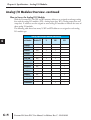
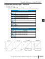
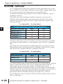
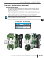
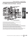
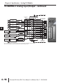
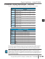
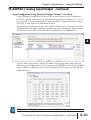
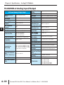
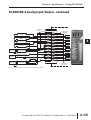
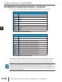
Chapter 6: Specifications - Analog I/O Modules
F2-8AD4DA-1 Analog Input/Output - continued
1
2
3
4
5
6
7
8
9
10
11
12
13
14
A
B
C
D
6–52
Input Resolution Selection (WYn+4)
If not using Do-more Designer version 1.1 or newer, each of the eight input channels can be
individually configured for 12, 14, or 16 bit resolution or disabled with memory address
WYn+4. (WYn: Starting WY address assigned to this module) 2 bits in this memory address
are assigned to each analog input channel.
Channel Resolution Selection Table
Input Resolution
RnH
RnL
(Resolution channel n (Resolution channel
High bit)
n Low bit)
12 bit
0
0
14 bit
0
1
16 bit
1
0
Disabled
1
1
The HEX data format is used to set up the input resolution as seen in the following example.
Example: An F2-8AD4DA-1 is installed in slot 0 and WY4 is used for the input resolution
selection. Input channels 1-4 are 12 bit, channel 5 is 14 bit, channel 6 is 16 bit, and channels
7 and 8 are disabled. In this case, 0xF900 needs to be written into WY4.
Use the MOVE instruction to write the Hex value 0xF900 into WY4.
Do-more H2 Series PLC User Manual, 1st Edition, Rev. C - H2-DM-M